
Related Manuals for Goulds Pumps IOM


Summary of Contents for Goulds Pumps IOM
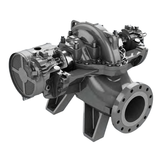
- Page 1 3610 i-FRAME API 610 11th Ed/ISO 13709 2nd Ed, API Type BB1 Single-Stage, Axially-Split, Between-Bearing...
-
Page 3: Table Of Contents
4.4.9 Perform complete alignment for a vertical correction..............35 4.4.10 Perform complete alignment for a horizontal correction.............. 36 4.5 Grout the baseplate..........................36 4.6 Piping checklists............................38 3610 i-FRAME API 610 11th Ed/ISO 13709 2nd Ed, API Type BB1 Single-Stage, Axially-Split, Between-Bearing IOM... - Page 4 6.2 Bearing maintenance ..........................73 6.3 Mechanical-seal maintenance......................... 73 6.4 Disassembly ............................74 6.4.1 Disassembly precautions ......................74 6.4.2 Tools required..........................75 6.4.3 Prepare for disassembly ....................... 75 3610 i-FRAME API 610 11th Ed/ISO 13709 2nd Ed, API Type BB1 Single-Stage, Axially-Split, Between-Bearing IOM...
- Page 5 8.2 Cross-sectional diagrams........................129 9 Other Relevant Documentation or Manuals....................132 9.1 For additional documentation ........................ 132 10 Local ITT Contacts ............................133 10.1 Regional offices........................... 133 3610 i-FRAME API 610 11th Ed/ISO 13709 2nd Ed, API Type BB1 Single-Stage, Axially-Split, Between-Bearing IOM...
-
Page 6: Introduction And Safety
ITT. If there is any uncertainty regarding the appropriate use of the equipment, please contact an ITT representative before proceeding. 3610 i-FRAME API 610 11th Ed/ISO 13709 2nd Ed, API Type BB1 Single-Stage, Axially-Split, Between-Bearing IOM... -
Page 7: Safety Terminology And Symbols
Hazard categories can either fall under hazard levels or let specific symbols replace the ordinary hazard level symbols. Electrical hazards are indicated by the following specific symbol: 3610 i-FRAME API 610 11th Ed/ISO 13709 2nd Ed, API Type BB1 Single-Stage, Axially-Split, Between-Bearing IOM... -
Page 8: Environmental Safety
For electrical installation recycling requirements, consult your local electric utility. 1.2.2.1 Recycling guidelines Always follow local laws and regulations regarding recycling. 1.2.3 User safety General safety rules These safety rules apply: 3610 i-FRAME API 610 11th Ed/ISO 13709 2nd Ed, API Type BB1 Single-Stage, Axially-Split, Between-Bearing IOM... - Page 9 Provide a suitable barrier around the work area, for example, a guard rail. • Make sure that all safety guards are in place and secure. • Make sure that you have a clear path of retreat. 3610 i-FRAME API 610 11th Ed/ISO 13709 2nd Ed, API Type BB1 Single-Stage, Axially-Split, Between-Bearing IOM...
- Page 10 Hold your eyelids apart forcibly with your fingers. in eyes Rinse the eyes with eyewash or running water for at least 15 minutes. Seek medical attention. 3610 i-FRAME API 610 11th Ed/ISO 13709 2nd Ed, API Type BB1 Single-Stage, Axially-Split, Between-Bearing IOM...
-
Page 11: Ex-Approved Products
Europe. ATEX deals with the control of potentially explosive atmospheres and the standards of equipment and protective systems used within these atmospheres. The relevance of the ATEX 3610 i-FRAME API 610 11th Ed/ISO 13709 2nd Ed, API Type BB1 Single-Stage, Axially-Split, Between-Bearing IOM... -
Page 12: Monitoring Equipment
The faults are due to defects in design, materials, or workmanship. • The faults are reported to an ITT representative within the warranty period. 3610 i-FRAME API 610 11th Ed/ISO 13709 2nd Ed, API Type BB1 Single-Stage, Axially-Split, Between-Bearing IOM... -
Page 13: Atex Considerations And Intended Use
• Any maintenance for Ex-approved products must conform to international and national standards (for example, EN 60079-17). 3610 i-FRAME API 610 11th Ed/ISO 13709 2nd Ed, API Type BB1 Single-Stage, Axially-Split, Between-Bearing IOM... - Page 14 Maintenance manual (IOM) can cause serious personal injury or damage to the equipment. This in- cludes any modification to the equipment or use of parts not provided by ITT Goulds Pumps. If there is any question regarding the intended use of the equipment, please contact an ITT Goulds representative before proceeding.
- Page 15 Lock out driver power to prevent electric shock, accidental start-up and physical injury. • NEVER start pump without proper prime (all models), or proper liquid level in self-priming pumps (Model 3796 and SP3298). 3610 i-FRAME API 610 11th Ed/ISO 13709 2nd Ed, API Type BB1 Single-Stage, Axially-Split, Between-Bearing IOM...
- Page 16 Rotate shaft by hand to ensure it rotates smoothly and there is no rubbing which could lead to excess heat generation, sparks and premature failure. 3610 i-FRAME API 610 11th Ed/ISO 13709 2nd Ed, API Type BB1 Single-Stage, Axially-Split, Between-Bearing IOM...
- Page 17 This is not permissible on the complete pump or partially-as- sembled machinery without further precautions being taken. ITT should be consulted in this context. 3610 i-FRAME API 610 11th Ed/ISO 13709 2nd Ed, API Type BB1 Single-Stage, Axially-Split, Between-Bearing IOM...
-
Page 18: Transportation And Storage
Risk of serious personal injury or equipment damage. Proper lifting practices are critical to safe transport of heavy equipment. Ensure that practices used are in compliance with all applicable regulations and standards. 3610 i-FRAME API 610 11th Ed/ISO 13709 2nd Ed, API Type BB1 Single-Stage, Axially-Split, Between-Bearing IOM... - Page 19 Hoist a bare pump using suitable slings under the bearing housing saddle on each end. Figure 2: Example of the proper lifting method for a bare pump Baseplate-mounted units have lifting points for use with proper lifting devices. 3610 i-FRAME API 610 11th Ed/ISO 13709 2nd Ed, API Type BB1 Single-Stage, Axially-Split, Between-Bearing IOM...
-
Page 20: Storage Guidelines
Treat bearing and machined surfaces so that they are well preserved. Refer to the drive unit and cou- pling manufacturers for their long-term storage procedures. 3610 i-FRAME API 610 11th Ed/ISO 13709 2nd Ed, API Type BB1 Single-Stage, Axially-Split, Between-Bearing IOM... - Page 21 2.3 Storage guidelines For questions about possible long-term storage treatment services, please contact your local ITT sales representative. 3610 i-FRAME API 610 11th Ed/ISO 13709 2nd Ed, API Type BB1 Single-Stage, Axially-Split, Between-Bearing IOM...
-
Page 22: Product Description
• Shouldered and locked to the shaft • Retained in the bearing frame to enable the bearing to carry both radial and thrust loads 3610 i-FRAME API 610 11th Ed/ISO 13709 2nd Ed, API Type BB1 Single-Stage, Axially-Split, Between-Bearing IOM... -
Page 23: General Description I-Alert®2 Equipment Condition Monitor
Item numbers can be found in the spare parts list. Refer to the nameplate on the pump casing for most of the information. See Parts List for item numbers. 3610 i-FRAME API 610 11th Ed/ISO 13709 2nd Ed, API Type BB1 Single-Stage, Axially-Split, Between-Bearing IOM... - Page 24 Customer contract or item number IMP. DIA. Rated impeller diameter, inches MAX. DIA. Maximum impeller diameter, inches STD. DIM. Standard ANSI dimensional code MAT'L Material of construction 3610 i-FRAME API 610 11th Ed/ISO 13709 2nd Ed, API Type BB1 Single-Stage, Axially-Split, Between-Bearing IOM...
- Page 25 Maximum permissible liquid tempera- perature in °C | °F ture in °C | °F 440 | 824 372 | 700 290 | 554 267 | 513 3610 i-FRAME API 610 11th Ed/ISO 13709 2nd Ed, API Type BB1 Single-Stage, Axially-Split, Between-Bearing IOM...
- Page 26 Ensure the pump driver and all other auxiliary components meet the required area classifica- tion at the site. If they are not compatible, do not operate the equipment and contact an ITT representative before proceeding. 3610 i-FRAME API 610 11th Ed/ISO 13709 2nd Ed, API Type BB1 Single-Stage, Axially-Split, Between-Bearing IOM...
-
Page 27: Installation
If the pump location is overhead, undertake special Consider a consultation with a noise specialist. precautions to reduce possible noise transmission. 3610 i-FRAME API 610 11th Ed/ISO 13709 2nd Ed, API Type BB1 Single-Stage, Axially-Split, Between-Bearing IOM... -
Page 28: Foundation Requirements
Provide a flat, substantial concrete foundation in order to prevent strain and distortion when you tighten the foundation bolts. Sleeve-type bolts Item Description Baseplate Foundation Sleeve Bolt Figure 8: Sleeve type bolts 3610 i-FRAME API 610 11th Ed/ISO 13709 2nd Ed, API Type BB1 Single-Stage, Axially-Split, Between-Bearing IOM... -
Page 29: Baseplate-Mounting Procedures
Make sure that all machined surfaces are free from burrs, rust, paint, or any other type of contami- nation. If necessary, use a honing stone to remove burrs. 3610 i-FRAME API 610 11th Ed/ISO 13709 2nd Ed, API Type BB1 Single-Stage, Axially-Split, Between-Bearing IOM... -
Page 30: Prepare The Foundation For Mounting
4.2.3 Install and level the baseplate NOTICE: Illustrations are for reference only and may not depict the particular pump model. Jackscrews Figure 10: Jackscrew locations, side view 3610 i-FRAME API 610 11th Ed/ISO 13709 2nd Ed, API Type BB1 Single-Stage, Axially-Split, Between-Bearing IOM... -
Page 31: Install The Pump, Driver, And Coupling
Mount and fasten the pump on the baseplate. Use applicable bolts. Mount the driver on the baseplate. Use applicable bolts and hand tighten. Install the coupling. See the installation instructions from the coupling manufacturer. 3610 i-FRAME API 610 11th Ed/ISO 13709 2nd Ed, API Type BB1 Single-Stage, Axially-Split, Between-Bearing IOM... -
Page 32: Pump-To-Driver Alignment
Final alignment (hot alignment) checks When After the first run This ensures correct alignment when both the pump and the driver are at op- erating temperature. 3610 i-FRAME API 610 11th Ed/ISO 13709 2nd Ed, API Type BB1 Single-Stage, Axially-Split, Between-Bearing IOM... -
Page 33: Permitted Indicator Values For Alignment Checks
Attach the other indicator (A) so that the indicator rod comes into contact with the inner end of the driver coupling half. This indicator is used to measure angular misalignment. 3610 i-FRAME API 610 11th Ed/ISO 13709 2nd Ed, API Type BB1 Single-Stage, Axially-Split, Between-Bearing IOM... -
Page 34: Perform Angular Alignment For A Vertical Correction
Remove shims in order to lower the feet of the driver at the shaft end. • Add shims in order to raise the feet of the driver at the other end. 3610 i-FRAME API 610 11th Ed/ISO 13709 2nd Ed, API Type BB1 Single-Stage, Axially-Split, Between-Bearing IOM... -
Page 35: Perform Angular Alignment For A Horizontal Correction
Perform one of these steps: • Slide the shaft end of the driver to the right. • Slide the opposite end to the left. 3610 i-FRAME API 610 11th Ed/ISO 13709 2nd Ed, API Type BB1 Single-Stage, Axially-Split, Between-Bearing IOM... -
Page 36: Perform Parallel Alignment For A Vertical Correction
Item Description Shims Figure 15: Example of incorrect vertical alignment (side view) 3610 i-FRAME API 610 11th Ed/ISO 13709 2nd Ed, API Type BB1 Single-Stage, Axially-Split, Between-Bearing IOM... -
Page 37: Perform Parallel Alignment For A Horizontal Correction
A unit is in complete alignment when both the angular indicator (A) and the parallel indicator (P) do not vary by more than 0.05 mm | 0.002 in. as measured at four points 90° apart. 3610 i-FRAME API 610 11th Ed/ISO 13709 2nd Ed, API Type BB1 Single-Stage, Axially-Split, Between-Bearing IOM... -
Page 38: Perform Complete Alignment For A Horizontal Correction
When you pour the grout, remove air bubbles from it by using one of these methods: • Puddle with a vibrator. • Pump the grout into place. Allow the grout to set. 3610 i-FRAME API 610 11th Ed/ISO 13709 2nd Ed, API Type BB1 Single-Stage, Axially-Split, Between-Bearing IOM... - Page 39 Grout Figure 18: Fill remainder of baseplate with grout Remove the leveling jackscrews after the grout hardens in order to remove any stress points. 3610 i-FRAME API 610 11th Ed/ISO 13709 2nd Ed, API Type BB1 Single-Stage, Axially-Split, Between-Bearing IOM...
-
Page 40: Piping Checklists
Guidelines for piping are given in the Hydraulic Institute Standards available from the Hydraulic Institute at 9 Sylvan Way, Parsippany, NJ 07054-3802. You must review this document before you install the pump. 3610 i-FRAME API 610 11th Ed/ISO 13709 2nd Ed, API Type BB1 Single-Stage, Axially-Split, Between-Bearing IOM... - Page 41 4.6.4 Flange face separation shall be within the gasket spacing ±1.5 mm | 1/16 in. Only one gasket per flanged connection shall be used. 3610 i-FRAME API 610 11th Ed/ISO 13709 2nd Ed, API Type BB1 Single-Stage, Axially-Split, Between-Bearing IOM...
-
Page 42: Suction-Piping Checklist
Check that the eccentric reducer at the suction flange of the pump has the follow- ing properties: • Sloping side down • Horizontal side at the top 3610 i-FRAME API 610 11th Ed/ISO 13709 2nd Ed, API Type BB1 Single-Stage, Axially-Split, Between-Bearing IOM... - Page 43 Use a foot valve with a diameter that is at least equiva- device for priming the pump is installed. lent to the diameter of the suction piping. 3610 i-FRAME API 610 11th Ed/ISO 13709 2nd Ed, API Type BB1 Single-Stage, Axially-Split, Between-Bearing IOM...
-
Page 44: Discharge Piping Checklist
You can size and install a minimum-flow orifice in a bypass line in order to prevent bypassing excessive flows. Consult your ITT representative for assistance in sizing a minimum-flow orifice. 3610 i-FRAME API 610 11th Ed/ISO 13709 2nd Ed, API Type BB1 Single-Stage, Axially-Split, Between-Bearing IOM... -
Page 45: Auxiliary-Piping Checklist
Re-check the alignment to make sure that If pipe strain exists, then correct the piping. pipe strain has not caused any misalign- ment. 3610 i-FRAME API 610 11th Ed/ISO 13709 2nd Ed, API Type BB1 Single-Stage, Axially-Split, Between-Bearing IOM... -
Page 46: Commissioning, Startup, Operation, And Shutdown
Refer to driver/coupling/gear manufacturer's installation and operation manuals (IOM) for specific instructions and recommendations. Precautions WARNING: The mechanical seal used in an Ex-classified environment must be properly certified. 3610 i-FRAME API 610 11th Ed/ISO 13709 2nd Ed, API Type BB1 Single-Stage, Axially-Split, Between-Bearing IOM... -
Page 47: Remove The Coupling Guard
Remove the nut, bolt, and washers from the driver half of the coupling guard. Remove the driver-side end plate. Remove the driver half of the coupling guard: Slightly spread the bottom apart. Lift upwards. 3610 i-FRAME API 610 11th Ed/ISO 13709 2nd Ed, API Type BB1 Single-Stage, Axially-Split, Between-Bearing IOM... -
Page 48: Check The Rotation
Motors with sleeve bearings may be manufactured with 6.35 or 12.7 mm | 1/4 or 1/2 in. end move- ment (float) in the motor rotor. For limited end-float arrangement, the gap between the coupling 3610 i-FRAME API 610 11th Ed/ISO 13709 2nd Ed, API Type BB1 Single-Stage, Axially-Split, Between-Bearing IOM... -
Page 49: Coupling Guard Assembly
Never operate a unit unless appropriate safety devices (guards, etc.) are properly installed. • Avoid death or serious injury. Assure mechanical seal guard is properly installed using supplied fastening hardware. 3610 i-FRAME API 610 11th Ed/ISO 13709 2nd Ed, API Type BB1 Single-Stage, Axially-Split, Between-Bearing IOM... - Page 50 If yes: Make any necessary coupling adjustments and then proceed to Step 2.. • If no: Complete these steps: Remove the spacer portion of the coupling. 3610 i-FRAME API 610 11th Ed/ISO 13709 2nd Ed, API Type BB1 Single-Stage, Axially-Split, Between-Bearing IOM...
- Page 51 Place one washer (534A) over the bolt (569E) and insert the bolt through the round hole at the front end of the guard half. 3610 i-FRAME API 610 11th Ed/ISO 13709 2nd Ed, API Type BB1 Single-Stage, Axially-Split, Between-Bearing IOM...
- Page 52 Place the end plate over the driver shaft and locate the end plate in the annular groove at the rear of the coupling guard half. 3610 i-FRAME API 610 11th Ed/ISO 13709 2nd Ed, API Type BB1 Single-Stage, Axially-Split, Between-Bearing IOM...
- Page 53 Figure 25: Slide to fit 10. Repeat Steps 3. through 5. for the center slots in the coupling guard. Firmly tighten all bolts (569E) on the guard assembly. 3610 i-FRAME API 610 11th Ed/ISO 13709 2nd Ed, API Type BB1 Single-Stage, Axially-Split, Between-Bearing IOM...
-
Page 54: Bearing Lubrication
6320 3401 7320/BECBM 3401 6224 3401 7320/BECBM 3401 Oil volume requirements for sleeve/ball This table shows the required amount of oil for oil-lubricated bearings. 3610 i-FRAME API 610 11th Ed/ISO 13709 2nd Ed, API Type BB1 Single-Stage, Axially-Split, Between-Bearing IOM... -
Page 55: Lubricating-Oil Requirements
Remove the oil filter (550A) and the oil filter plug (113Q) from the bearing frame (134). See Figure 26: Oil filter and plug removal on page 3610 i-FRAME API 610 11th Ed/ISO 13709 2nd Ed, API Type BB1 Single-Stage, Axially-Split, Between-Bearing IOM... - Page 56 See Figure 28: Filter kit on page 3610 i-FRAME API 610 11th Ed/ISO 13709 2nd Ed, API Type BB1 Single-Stage, Axially-Split, Between-Bearing IOM...
-
Page 57: Lubricate The Bearings With Oil
5.5.5 Lubricate the bearings with oil WARNING: Risk of explosive hazard and premature failure from sparks and heat generation. Ensure bearings are properly lubricated prior to startup. 3610 i-FRAME API 610 11th Ed/ISO 13709 2nd Ed, API Type BB1 Single-Stage, Axially-Split, Between-Bearing IOM... -
Page 58: Convert To Oil-Mist Lubrication
Make sure that pipe threads are clean and apply thread sealant to plugs and fittings. NOTICE: In both housings install bearing end cover (160) designed for oil mist. 3610 i-FRAME API 610 11th Ed/ISO 13709 2nd Ed, API Type BB1 Single-Stage, Axially-Split, Between-Bearing IOM... -
Page 59: Thrust Bearing Cooling Fan (Optional)
Electrical connections must be made by certified electricians in compliance with all international, national, state, and local rules. • Refer to driver/coupling/gear manufacturer's installation and operation manuals (IOM) for specific instructions and recommendations. 3610 i-FRAME API 610 11th Ed/ISO 13709 2nd Ed, API Type BB1 Single-Stage, Axially-Split, Between-Bearing IOM... -
Page 60: Lubricate The Bearings With Pure Or Purge-Oil Mist (Optional)
Oil mist is recommended for use on ball bearing arrangements only. See convert to oil mist lu- brication. Prepare the oil-mist generator according to the manufacturer's instructions. 3610 i-FRAME API 610 11th Ed/ISO 13709 2nd Ed, API Type BB1 Single-Stage, Axially-Split, Between-Bearing IOM... -
Page 61: Lubricate The Bearings With Pressurized Lubrication
33: Oil feed location on page Connect the bearing housing drain piping back to the lubrication oil skid as shown in Figure 34: Oil drain locations on page 3610 i-FRAME API 610 11th Ed/ISO 13709 2nd Ed, API Type BB1 Single-Stage, Axially-Split, Between-Bearing IOM... -
Page 62: Lubricate The Bearings After A Shutdown Period
Flush the bearing housing with the proper lubricating oil to ensure oil quality after cleaning. Refer to Reassembly section for proper bearing greasing procedure. 3610 i-FRAME API 610 11th Ed/ISO 13709 2nd Ed, API Type BB1 Single-Stage, Axially-Split, Between-Bearing IOM... -
Page 63: Shaft Sealing With A Mechanical Seal
| 5 to 15 psi greater than the seal chamber pres- sure. The injection rate must be 2 to 8 lpm | 0.5 to 2 gpm. 3610 i-FRAME API 610 11th Ed/ISO 13709 2nd Ed, API Type BB1 Single-Stage, Axially-Split, Between-Bearing IOM... -
Page 64: Pump Priming
During long idle periods, the pump can also lose its prime through leakage from the stuffing boxes. 3610 i-FRAME API 610 11th Ed/ISO 13709 2nd Ed, API Type BB1 Single-Stage, Axially-Split, Between-Bearing IOM... -
Page 65: Prime The Pump With A Separate Hand Or Manually Controlled Priming Pump
The pump can be primed by pumping liquid into the casing until liquid comes out of the open air vent with the plug removed. 3610 i-FRAME API 610 11th Ed/ISO 13709 2nd Ed, API Type BB1 Single-Stage, Axially-Split, Between-Bearing IOM... -
Page 66: Prime The Pump By Bypassing The Discharge Check Valve
The valve in the bypass line can be left open so that loss through the foot valve is constantly replen- ished from the discharge line left open during idle periods. 3610 i-FRAME API 610 11th Ed/ISO 13709 2nd Ed, API Type BB1 Single-Stage, Axially-Split, Between-Bearing IOM... -
Page 67: Prime The Pump With An Ejector
Open the discharge gate valve. Valve S Ejector Valve E Steam, compressed air, or water under pressure Discharge gate valve Figure 39: Priming the pump with an ejector 3610 i-FRAME API 610 11th Ed/ISO 13709 2nd Ed, API Type BB1 Single-Stage, Axially-Split, Between-Bearing IOM... -
Page 68: Prime With An Automatic Primer Pump
Reinstall the plugs after confirming. Before you start the pump, you must perform these tasks: 3610 i-FRAME API 610 11th Ed/ISO 13709 2nd Ed, API Type BB1 Single-Stage, Axially-Split, Between-Bearing IOM... -
Page 69: I-Alert®2 Equipment Health Monitor
Risk of equipment damage from unexpected heat generation. Do not overload the driver. Ensure that the pump operating conditions are suitable for the driver. The driver can over- load in these circumstances: 3610 i-FRAME API 610 11th Ed/ISO 13709 2nd Ed, API Type BB1 Single-Stage, Axially-Split, Between-Bearing IOM... - Page 70 Note that different liquids freeze at different temperatures. Some pump designs do not drain completely and may require flushing with a liquid that doesn't freeze. 3610 i-FRAME API 610 11th Ed/ISO 13709 2nd Ed, API Type BB1 Single-Stage, Axially-Split, Between-Bearing IOM...
-
Page 71: Shut Down The Pump
Run the unit under actual operating conditions for enough time to bring the pump, driver, and asso- ciated system to operating temperature. Shut down the pump and the driver. 3610 i-FRAME API 610 11th Ed/ISO 13709 2nd Ed, API Type BB1 Single-Stage, Axially-Split, Between-Bearing IOM... -
Page 72: Doweling The Pump Casing
12. Remove the coupling guard. Refer to . 13. Check and confirm the alignment while the unit is still hot. 3610 i-FRAME API 610 11th Ed/ISO 13709 2nd Ed, API Type BB1 Single-Stage, Axially-Split, Between-Bearing IOM... - Page 73 5.21 Doweling the pump casing 14. Dowel the driver feet. See the driver IOM for details. 3610 i-FRAME API 610 11th Ed/ISO 13709 2nd Ed, API Type BB1 Single-Stage, Axially-Split, Between-Bearing IOM...
-
Page 74: Maintenance
• Check the shaft alignment, and realign as required. Annual inspections Perform these inspections one time each year: 3610 i-FRAME API 610 11th Ed/ISO 13709 2nd Ed, API Type BB1 Single-Stage, Axially-Split, Between-Bearing IOM... -
Page 75: Bearing Maintenance
If the seal has been installed in the pump by ITT, these clips have already been disengaged. 3610 i-FRAME API 610 11th Ed/ISO 13709 2nd Ed, API Type BB1 Single-Stage, Axially-Split, Between-Bearing IOM... -
Page 76: Disassembly
Risk of serious personal injury from exposure to hazardous or toxic liquids. A small amount of liquid will be present in certain areas like the seal chamber upon disassembly. 3610 i-FRAME API 610 11th Ed/ISO 13709 2nd Ed, API Type BB1 Single-Stage, Axially-Split, Between-Bearing IOM... -
Page 77: Tools Required
Remove the oil drain plugs (408A) from the bottom of the bearing housings (134, 134A) and drain the oil. Dispose of the oil in accordance with applicable regulations. 3610 i-FRAME API 610 11th Ed/ISO 13709 2nd Ed, API Type BB1 Single-Stage, Axially-Split, Between-Bearing IOM... - Page 78 Reposition the setting tabs in order to maintain the position of the mechanical seal, for both seals. Refer to the seal installation drawing provided by the manufacturer. 3610 i-FRAME API 610 11th Ed/ISO 13709 2nd Ed, API Type BB1 Single-Stage, Axially-Split, Between-Bearing IOM...
-
Page 79: Disassemble The Radial End (Ball Bearing Pumps)
Loosen the setscrew (388L) on the oil ring sleeve (324) and remove the sleeve. 10. Use a bearing puller in order to remove the radial bearing (168) from the shaft. 3610 i-FRAME API 610 11th Ed/ISO 13709 2nd Ed, API Type BB1 Single-Stage, Axially-Split, Between-Bearing IOM... -
Page 80: Disassemble The Thrust End (Ball Bearing Pumps)
The inner race on this inner duplex bearing remains on the shaft when the bearing is pulled. Re- move this inner race by applying heat. Do this away from the pump site. 3610 i-FRAME API 610 11th Ed/ISO 13709 2nd Ed, API Type BB1 Single-Stage, Axially-Split, Between-Bearing IOM... -
Page 81: Disassemble The Radial End (Sleeve/Ball Bearing Pumps)
Remove the oil filter (550A) and filter plug (113Q) from the bearing frame (134) Remove the two taper pins between the upper and lower halves of the bearing housing (134). 3610 i-FRAME API 610 11th Ed/ISO 13709 2nd Ed, API Type BB1 Single-Stage, Axially-Split, Between-Bearing IOM... - Page 82 Remove the lower half of the bearing housing. 12. (Optional) Remove the studs (371T). 13. Remove the outboard labyrinth seal (332A) and the inboard labyrinth seal (333A) and oil ring (114). 3610 i-FRAME API 610 11th Ed/ISO 13709 2nd Ed, API Type BB1 Single-Stage, Axially-Split, Between-Bearing IOM...
-
Page 83: Disassemble The Thrust End (Sleeve/Ball Bearing Pumps)
Move the oil ring (114) aside, it cannot be removed until the lower bearing housing is removed. Remove the upper half of the sleeve bearing (117). 3610 i-FRAME API 610 11th Ed/ISO 13709 2nd Ed, API Type BB1 Single-Stage, Axially-Split, Between-Bearing IOM... - Page 84 Remove the thrust locknut (136) and the lockwasher (382) from the shaft. 16. Remove the oil ring sleeve (443B). 17. Remove bearing retainer (361A). 3610 i-FRAME API 610 11th Ed/ISO 13709 2nd Ed, API Type BB1 Single-Stage, Axially-Split, Between-Bearing IOM...
- Page 85 Never apply heat at the pump site for this reason. Heat can also distort machined surfaces. 19. If applicable - Remove bearing spacer (443V). 20. Remove the inboard labyrinth seals (333A) and oil ring (114). 3610 i-FRAME API 610 11th Ed/ISO 13709 2nd Ed, API Type BB1 Single-Stage, Axially-Split, Between-Bearing IOM...
-
Page 86: Disassemble The Radial End (Sleeve/Tilt Pumps)
Tighten the two jack bolts on the horizontal parting flanges of the bearing housing (134) in order to separate the two halves. Remove the top half of the bearing housing (134). 3610 i-FRAME API 610 11th Ed/ISO 13709 2nd Ed, API Type BB1 Single-Stage, Axially-Split, Between-Bearing IOM... - Page 87 10. Remove the dowel pins (469J) that hold the lower half of the bearing housing to the casing flange. Figure 56: Radial dowel pin removal Loosen and remove the nuts (427J) that hold the bearing housing (134) in place. 3610 i-FRAME API 610 11th Ed/ISO 13709 2nd Ed, API Type BB1 Single-Stage, Axially-Split, Between-Bearing IOM...
-
Page 88: Disassemble The Thrust End (Sleeve/Tilt Pumps)
(219). If the pump was not supplied with a main oil shaft pump (219), go to step 4. Remove the hex cap screws (370N) to remove the oil pump adapter (318A). 3610 i-FRAME API 610 11th Ed/ISO 13709 2nd Ed, API Type BB1 Single-Stage, Axially-Split, Between-Bearing IOM... - Page 89 (134A). 23. Remove the dowel pins (469J) that hold the lower half of the bearing housing to the casing flange. 3610 i-FRAME API 610 11th Ed/ISO 13709 2nd Ed, API Type BB1 Single-Stage, Axially-Split, Between-Bearing IOM...
-
Page 90: Guidelines For I-Alert®2 Equipment Health Monitor Disposal
This product contains Lithium Thionyl Chloride. Contact your local waste management companies to pro- vide assistance in the disposal of the device that contain this type of battery. 3610 i-FRAME API 610 11th Ed/ISO 13709 2nd Ed, API Type BB1 Single-Stage, Axially-Split, Between-Bearing IOM... -
Page 91: Disassemble The Rotating Assembly
Cast lifting lugs in upper half are intended for upper half removal from the pump. They are not intended to be used to lift the entire pump. 3610 i-FRAME API 610 11th Ed/ISO 13709 2nd Ed, API Type BB1 Single-Stage, Axially-Split, Between-Bearing IOM... - Page 92 This value is required for the correct positioning of the impeller in the casing at reassembly. The X dimension is pre-set at the factory. Refer to the Impeller setting table. 3610 i-FRAME API 610 11th Ed/ISO 13709 2nd Ed, API Type BB1 Single-Stage, Axially-Split, Between-Bearing IOM...
-
Page 93: Preassembly Inspections
Wear ring clearances that exceed the values in the Minimum running clearances table NOTICE: When clearances between the rings become excessive (increase by 50%), hydraulic perform- ance decreases substantially. 3610 i-FRAME API 610 11th Ed/ISO 13709 2nd Ed, API Type BB1 Single-Stage, Axially-Split, Between-Bearing IOM... - Page 94 You must have extremely accurate tooling equipment to balance impellers to ISO 1940-1, grade G2.5. Do not attempt to balance impellers to this criteria unless this type of tooling and equipment is available. 3610 i-FRAME API 610 11th Ed/ISO 13709 2nd Ed, API Type BB1 Single-Stage, Axially-Split, Between-Bearing IOM...
- Page 95 Locknut surfaces must be smooth and free of grooves and scratches, especially in the areas indicated by arrows in the figure. Also check the outside diameter of the locknuts. Figure 65: Impeller locknut inspection 3610 i-FRAME API 610 11th Ed/ISO 13709 2nd Ed, API Type BB1 Single-Stage, Axially-Split, Between-Bearing IOM...
-
Page 96: Shaft Replacement Guidelines
Check the bearing fits of the shaft. If any are outside the tolerances shown in the Bearing fits and toler- ances table, then replace the shaft. 3610 i-FRAME API 610 11th Ed/ISO 13709 2nd Ed, API Type BB1 Single-Stage, Axially-Split, Between-Bearing IOM... -
Page 97: Bearings Inspection
6.5.3 Bearings inspection Condition of bearings Do not reuse bearings. The condition of the bearings provides useful information on operating conditions in the bearing frame. 3610 i-FRAME API 610 11th Ed/ISO 13709 2nd Ed, API Type BB1 Single-Stage, Axially-Split, Between-Bearing IOM... - Page 98 Check that the bearing housings are very clean, with no burrs. • Remove all loose and foreign material. • Check the bearing housing bores against the values in the Ball bearing fits table. 3610 i-FRAME API 610 11th Ed/ISO 13709 2nd Ed, API Type BB1 Single-Stage, Axially-Split, Between-Bearing IOM...
-
Page 99: Replace The Wear Parts
(101) wear-ring seats. WARNING: Wear insulated gloves when you handle rings. Rings will be hot and can cause physical injury. 3610 i-FRAME API 610 11th Ed/ISO 13709 2nd Ed, API Type BB1 Single-Stage, Axially-Split, Between-Bearing IOM... - Page 100 When the impeller assembly is supplied as a spare part (impeller with wear rings), the wear rings are machined to the required dimension. 3610 i-FRAME API 610 11th Ed/ISO 13709 2nd Ed, API Type BB1 Single-Stage, Axially-Split, Between-Bearing IOM...
- Page 101 0.94 mm | 0.037 in. plus 1 mm for each additional 1 mm | 0.001 inch for each additional inch of diameter or fraction thereof . 3610 i-FRAME API 610 11th Ed/ISO 13709 2nd Ed, API Type BB1 Single-Stage, Axially-Split, Between-Bearing IOM...
-
Page 102: Reassembly
Install the casing wear rings (164) over each impeller ring (142). Be certain the smaller outer diameter is nearest the impeller when installing. Install the throat bushing (125) on each side of the impeller. 3610 i-FRAME API 610 11th Ed/ISO 13709 2nd Ed, API Type BB1 Single-Stage, Axially-Split, Between-Bearing IOM... -
Page 103: Install The Rotating Element Assembly
Apply an anti-seize compound to the bolts and to the face of the head where the nuts make contact. Mount the cartridge mechanical seal (383) on the shaft (122). Do not tighten the gland nuts (355) at this time. 3610 i-FRAME API 610 11th Ed/ISO 13709 2nd Ed, API Type BB1 Single-Stage, Axially-Split, Between-Bearing IOM... - Page 104 360°. If the total indicator reading exceeds 0.127 mm | 0.005 in., determine the cause and make correc- tions. 3610 i-FRAME API 610 11th Ed/ISO 13709 2nd Ed, API Type BB1 Single-Stage, Axially-Split, Between-Bearing IOM...
-
Page 105: Assemble The Thrust End (Ball Bearing Pumps)
Clean the end cover with a solvent. Fit the labyrinth seal (333A) into the bore of the cover (160). Tap the seal in with a hammer. 3610 i-FRAME API 610 11th Ed/ISO 13709 2nd Ed, API Type BB1 Single-Stage, Axially-Split, Between-Bearing IOM... - Page 106 • If the outer races are loose, the bearing is not properly seated and must be retightened. When you have achieved the proper bearing assembly, set the lockwasher tab in the slot in the locknut. 3610 i-FRAME API 610 11th Ed/ISO 13709 2nd Ed, API Type BB1 Single-Stage, Axially-Split, Between-Bearing IOM...
- Page 107 This table shows the clearance requirements between the thrust bearing end cover and the bearing: Bearing type Clearance in millimeters | inches Ball/ball 0.127-0.254 | 0.005-0.010 Sleeve/ball 0.127-0.254 | 0.005-0.010 Sleeve/tilt pad 0.203-0.279 | 0.008-0.011 3610 i-FRAME API 610 11th Ed/ISO 13709 2nd Ed, API Type BB1 Single-Stage, Axially-Split, Between-Bearing IOM...
-
Page 108: Assemble The Radial End (Ball Bearing Pumps)
Do not use a torch and do not force. Coat the internal surface of the bearings with the lubricant that is to be used in service. 3610 i-FRAME API 610 11th Ed/ISO 13709 2nd Ed, API Type BB1 Single-Stage, Axially-Split, Between-Bearing IOM... -
Page 109: Assemble The Thrust End (Sleeve/Ball Bearing Pumps)
Install the cartridge mechanical seal (383) on the shaft (122) and align the mechanical seal pilot with the seal chamber bore of the casing. Install the mechanical seal studs (353) and hex nuts (355). 3610 i-FRAME API 610 11th Ed/ISO 13709 2nd Ed, API Type BB1 Single-Stage, Axially-Split, Between-Bearing IOM... - Page 110 • Risk of physical injury from hot bearings. Wear insulated gloves when using a bearing heater. NOTICE: Do not use a torch and do not force. 3610 i-FRAME API 610 11th Ed/ISO 13709 2nd Ed, API Type BB1 Single-Stage, Axially-Split, Between-Bearing IOM...
- Page 111 10. Place the installed inboard labyrinth seal (333A) in the lower housing. Finger tighten the lower housing to the head-bearing flange with the head-to-bearing housing studs (371T) and nuts (427J). 3610 i-FRAME API 610 11th Ed/ISO 13709 2nd Ed, API Type BB1 Single-Stage, Axially-Split, Between-Bearing IOM...
- Page 112 When new bearings are installed, you must measure the axial end play: Bolt the end cover to the thrust housing. Move the shaft axially from the coupling end. 3610 i-FRAME API 610 11th Ed/ISO 13709 2nd Ed, API Type BB1 Single-Stage, Axially-Split, Between-Bearing IOM...
-
Page 113: Assemble The Radial End (Sleeve/Ball Bearing Pumps)
Make sure that the expulsion port is at the 6 o'clock position and is properly seated. Position the dowel pins between the upper and lower halves of the bearing housing. Tighten the bearing-housing hex screws. 3610 i-FRAME API 610 11th Ed/ISO 13709 2nd Ed, API Type BB1 Single-Stage, Axially-Split, Between-Bearing IOM... -
Page 114: Assemble The Thrust End (Sleeve/Tilt Pumps)
Place the installed inboard labyrinth seal (333A) in the lower housing. Finger tighten the lower housing to the case-to bearing housing flange with the case-to-bearing housings studs (371T) and nuts (427J). 3610 i-FRAME API 610 11th Ed/ISO 13709 2nd Ed, API Type BB1 Single-Stage, Axially-Split, Between-Bearing IOM... - Page 115 (441A). Do not tighten the axial proximity probes all the way down until they come into contact with the thrust collar. The axial proximity probes should be set at .050” away from the thrust collar. 3610 i-FRAME API 610 11th Ed/ISO 13709 2nd Ed, API Type BB1 Single-Stage, Axially-Split, Between-Bearing IOM...
-
Page 116: Assemble The Radial End (Sleeve/Tilt Pumps)
Do not set the mechanical seal sleeve set screws at this time; endplay must be checked first or damage to the seal faces could occur. Install the inboard labyrinth seal (333A). Figure 84: Radial inboard labyryth seal installation 3610 i-FRAME API 610 11th Ed/ISO 13709 2nd Ed, API Type BB1 Single-Stage, Axially-Split, Between-Bearing IOM... -
Page 117: Attach The I-Alert®2 Equipment Health Monitor To The Pump
Install the hex cap screws that connect the upper and lower halves of the bearing housing (134). ® 6.6.9 Attach the i-ALERT 2 Equipment Health Monitor to the pump Tools required: • 5/32 inch hex wrench 3610 i-FRAME API 610 11th Ed/ISO 13709 2nd Ed, API Type BB1 Single-Stage, Axially-Split, Between-Bearing IOM... -
Page 118: Post-Assembly Checks
1628 11 | 8 7/16–14 0.1063 4837 35 | 26 2232 16 | 12 1/2–13 0.1419 6456 54 | 40 2980 26 | 19 3610 i-FRAME API 610 11th Ed/ISO 13709 2nd Ed, API Type BB1 Single-Stage, Axially-Split, Between-Bearing IOM... - Page 119 9137 | 6739 125013 6092 | 4493 5.967 187961 9557 | 7049 125307 6371 | 4699 6.506 204939 10419 | 7685 136626 6946 | 5123 3610 i-FRAME API 610 11th Ed/ISO 13709 2nd Ed, API Type BB1 Single-Stage, Axially-Split, Between-Bearing IOM...
- Page 120 16814 | 12401 size restrictions in the 2.875-8 5.953 395875 19289 | 14227 material specification 5.967 396806 20175 | 14880 6.506 432649 21997 | 16224 3610 i-FRAME API 610 11th Ed/ISO 13709 2nd Ed, API Type BB1 Single-Stage, Axially-Split, Between-Bearing IOM...
- Page 121 150368 7645 | 5639 6.506 163951 8336 | 6148 6.6.11.4 Spare parts Critical service spare parts For critical services, stock these parts, where applicable: 3610 i-FRAME API 610 11th Ed/ISO 13709 2nd Ed, API Type BB1 Single-Stage, Axially-Split, Between-Bearing IOM...
- Page 122 • Labyrinth seal, outboard (332C) • Labyrinth seal, inboard (333A) • Case parting gasket (351) • Bearing lockwasher (382) • Bearing end-cover gasket (360A) 3610 i-FRAME API 610 11th Ed/ISO 13709 2nd Ed, API Type BB1 Single-Stage, Axially-Split, Between-Bearing IOM...
-
Page 123: Troubleshooting
Hydraulic Institute Standards Manual. The pump is cavitating. Locate and correct the system problem. The mechanical seal is The packing gland is not adjusted proper- leaking excessively. 3610 i-FRAME API 610 11th Ed/ISO 13709 2nd Ed, API Type BB1 Single-Stage, Axially-Split, Between-Bearing IOM... -
Page 124: Alignment Troubleshooting
2 Equipment Health Monitor troubleshooting ® ® To troubleshoot the i-ALERT 2 Equipment Health Monitor, please refer to the i-ALERT 2 Equipment Health Monitor IOM or https://www.ittproservices.com/Our-Services/Aftermarket-Products/Monitoring/i- ALERT2-condition-monitor/ 3610 i-FRAME API 610 11th Ed/ISO 13709 2nd Ed, API Type BB1 Single-Stage, Axially-Split, Between-Bearing IOM... -
Page 125: Parts Listings And Cross-Sectionals
6983 2446 6983 6186 2229 2229 Thrust End Pipe Nipple, 133A 6501 Watch Dog 134, Bearing 1212 134A Housing Bearing Lock- nut - Thrust 3610 i-FRAME API 610 11th Ed/ISO 13709 2nd Ed, API Type BB1 Single-Stage, Axially-Split, Between-Bearing IOM... - Page 126 2229 2229 Ring Set Screw, 222S 2229 Coupling Nut * Use 2252 for Temperature > 177°C | 350°F Set Screw, 222V 2229 Cooling Fan 3610 i-FRAME API 610 11th Ed/ISO 13709 2nd Ed, API Type BB1 Single-Stage, Axially-Split, Between-Bearing IOM...
- Page 127 - Discharge 351R Gasket, 1st Stage Spacer 351W Gasket, 2nd Stage Spacer Stud - Gland 5426 Nut - Gland 5427 356A Stud - Casing 2239 3610 i-FRAME API 610 11th Ed/ISO 13709 2nd Ed, API Type BB1 Single-Stage, Axially-Split, Between-Bearing IOM...
- Page 128 390C Tilt Pad Cooling Fan - 392B 1425 Roll Pin, Filler Plate Coupling Key 2213 Pipe Plug, 408A Drain 408L Pipe Plug- Bearing Cool- 3610 i-FRAME API 610 11th Ed/ISO 13709 2nd Ed, API Type BB1 Single-Stage, Axially-Split, Between-Bearing IOM...
- Page 129 Sleeve Bear- 469J Taper Pin 2210 469Y Hex Cap 2229 Screw - Bear- ing Retainer Pipe Plug, Vi- 492V 2210 bration Bearing Cool- ing Option 3610 i-FRAME API 610 11th Ed/ISO 13709 2nd Ed, API Type BB1 Single-Stage, Axially-Split, Between-Bearing IOM...
- Page 130 761B i-ALERT2 18-8 Stainless with Nylon 12 Cover Shaft Fan 785C 3201 Guard 785D Cowling 3201 813F Hex Nut - 2229 Bearing Re- tainer 3610 i-FRAME API 610 11th Ed/ISO 13709 2nd Ed, API Type BB1 Single-Stage, Axially-Split, Between-Bearing IOM...
-
Page 131: Cross-Sectional Diagrams
8.2 Cross-sectional diagrams 8.2 Cross-sectional diagrams Model 3610 i-FRAME - ball/ball 3610 i-FRAME API 610 11th Ed/ISO 13709 2nd Ed, API Type BB1 Single-Stage, Axially-Split, Between-Bearing IOM... - Page 132 8.2 Cross-sectional diagrams Model 3610 i-FRAME - sleeve/ball 3610 i-FRAME API 610 11th Ed/ISO 13709 2nd Ed, API Type BB1 Single-Stage, Axially-Split, Between-Bearing IOM...
- Page 133 8.2 Cross-sectional diagrams Model 3610 i-FRAME sleeve/tilt 3610 i-FRAME API 610 11th Ed/ISO 13709 2nd Ed, API Type BB1 Single-Stage, Axially-Split, Between-Bearing IOM...
-
Page 134: Other Relevant Documentation Or Manuals
9 Other Relevant Documentation or Manuals 9 Other Relevant Documentation or Manuals 9.1 For additional documentation For any other relevant documentation or manuals, contact your ITT representative. 3610 i-FRAME API 610 11th Ed/ISO 13709 2nd Ed, API Type BB1 Single-Stage, Axially-Split, Between-Bearing IOM... -
Page 135: Local Itt Contacts
Huechuraba Santiago 8580000 Chile Middle East and Africa ITT - Goulds Pumps +30 210-677-0770 +30 210-677-5642 Achileos Kyrou 4 Neo Psychiko 115 25 Athens Greece 3610 i-FRAME API 610 11th Ed/ISO 13709 2nd Ed, API Type BB1 Single-Stage, Axially-Split, Between-Bearing IOM... - Page 136 Visit our website for the latest version of this document and more information: http://www.gouldspumps.com ITT Goulds Pumps Inc. 240 Fall Street Seneca Falls, NY 13148 Form IOM.3610i-FRAME.en-US.2021-11 ©2021 ITT Goulds Pumps The original instruction is in English. All non-English instructions are translations of the original instruction.
Need help?
Do you have a question about the IOM and is the answer not in the manual?
Questions and answers