
Related Manuals for Goulds Pumps VIC


Summary of Contents for Goulds Pumps VIC
- Page 1 INSTRUCTION MANUAL IOMGWVICR01-EN MODEL VIC VERTICAL INDUSTRIAL TURBINE CAN PUMPS INSTALLATION, OPERATION AND MAINTENANCE INSTRUCTIONS...
- Page 2 The design, materials, and workmanship incorporated in the construction of the Goulds Water Technology VIC pumps makes them capable of giving long, trouble-free service. The life and satisfactory service of any mechanical unit, however, is enhanced and extended by correct application, proper installation, periodic inspection, condition monitoring and careful maintenance.
-
Page 3: Table Of Contents
Table of Contents SUBJECT PAGE SECTION 1 – Safety ..............................4 SECTION 2 – General Information ..........................4 Introduction ................................4 Receiving and Checking ............................4 Materials and Equipment Required ........................... 5 Storage ..................................5 General Description ..............................6 SECTION 3 – Installation ............................9 Foundation / Piping .............................. -
Page 4: Section 1 - Safety
The design, material, and workmanship incorporated NOTICE: INDICATES SPECIAL INSTRUCTIONS in the construction of Goulds Water Technology VIC WHICH ARE VERY IMPORTANT AND MUST BE pumps makes them capable of giving long, trouble FOLLOWED. -
Page 5: Materials And Equipment Required
This section is intended to be of general assistance to Any shortages or damages should be immediately called users of Goulds Water Technology VIC pumps. It shall to the attention of the local freight agent of the carrier by not modify, amend and/or otherwise alter the scope... -
Page 6: General Description
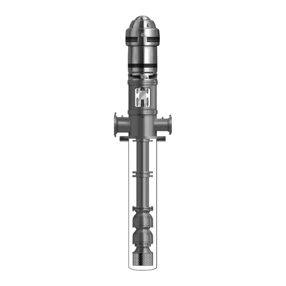
GENERAL DESCRIPTION on the design requirements. They are fastened to the The model VIC pump is a vertical industrial turbine type pump shaft by taperlocks. For temperatures over 140°F pump installed in a can (barrel), and is designed to meet (60°C) and in the larger size bowls (over 18”), impellers... - Page 7 CLEAN-OUT PIPE (OPTIONAL) BARREL BOWL ASSEMBLY PUMP SHAFT INTERMEDIATE BOWL INTER. BOWL BEARING IMPELLER TAPERLOCK WEAR RING (OPTIONAL) HEX BOLT SAND COLLAR SUCTION BOWL/BELL SUCTION BEARING PLUG Figure 1 VIC Pump with Solid Shaft Motor, Fabricated T-Head, Mechanical Seal and Flanged Column...
- Page 8 LINESHAFT COUPLING BARREL BOWL ASSEMBLY BOWL SHAFT INTERMEDIATE BOWL INTER. BOWL BEARING IMPELLER TAPERLOCK WEAR RING (OPTIONAL) HEX BOLT SAND COLLAR SUCTION BOWL/BELL SUCTION BEARING PLUG Figure 2 VIC Pump with Cast L-Head, VHS Motor, Packed stuffing Box and flanged column...
-
Page 9: Section 3 - Installation
Installation – SECTION 3 Bolts should be sized and located in accordance with the dimensions given on the Certified Pump When pumping unit is installed in a potentially Outline Drawing, if provided. The pipe sleeve explosive environment, the instruction after allows movement for the final positioning of the symbol must be followed. -
Page 10: Pump Installation
3. Pour grout between sub base or barrel flange and PUMP INSTALLATION concrete foundation, up to level of dam. Remove When pumping unit is installed in a potentially air bubbles from grout as it is poured by puddling, explosive environment, the instruction after the using a vibrator, or pumping the grout into place. -
Page 11: Installing The Column
1. Prior to installing the bowl assembly, check that Coat a thin film of oil to the threads on the lineshaft all capscrews are tight. Turn the pump shaft by (646) and the coupling (649) (for non-galling hand and make sure it turns freely. Remove all material, or Molykote if galling material). -
Page 12: Installing The Discharge Head
Secure INSTALLING THE DISCHARGE HEAD stuffing box with capscrews. VIC Pumps are provided with either “T” type or “L” type 2. Grease the packing ring (620) for easier installation. head. Install the discharge head as follows: 3. -
Page 13: Installing The Mechanical Seal
Check that the split gland is square in the shaft packing. When further clean up is required, CAUTION stuffing box. Cocking can cause uneven protect by covering the inside of the pump seal compression of packing and damage to the shaft or sleeve housing. -
Page 14: Installing The Driver
INSTALLING THE DRIVER 6. Lower the head shaft through the motor quill shaft to meet the shaft coupling. Apply a thin film of oil When installed in a potentially explosive to head shaft threads (if non-galling material) and environment, please ensure the motor is screw into the shaft coupling (located above the properly certified. - Page 15 3. There are several methods of running engines 5. Normal impeller clearance for the open impeller is without electric motors and vice versa, requiring considered to be 0.015” for the first 10 feet of the simple adjustment to the combination drive, but column length and 0.010”...
- Page 16 indicator prior to connecting the pump coupling to Impeller adjustment is identical for all motors and the solid shaft motor. Consult the applicable motor right angle gear drives. Adjustment is accomplished by manufacturers instruction manual for detailed turning the adjusting plate (613). (See figure 11 or 12). information on motor shaft end play.
- Page 17 2. After impeller adjustment, align adjusting plate ENCLOSED IMPELLERS (613) with the pump hub (614), and tightly draw For enclosed impellers obtain the clearance between the coupling flanges together with capscrews (759) and adjusting plate and driver hub or spacer as specified on nuts (735).
- Page 18 3. Lower the drive shaft through the quill of the thrust pot assembly to meet the shaft coupling. Apply a thin film of oil to the head shaft thread and screw into the shaft coupling. 4. For unit with mechanical seal and flanged coupling, install the spacer flange coupling as instructed on page 16.
- Page 19 ITEM DESCRIPTION ITEM DESCRIPTION Thrust Pot Body Flexible Shaft Coupling Tube - Oil Retaining Gib Key Thrust Bearing Key (Motor Shaft) Capscrew - Head to Thrust Pot Setscrew Washer - Head to Thrust Pot Round Head Screw for Coupling Guard Hex Nut - Head to Thrust Pot Washer Coupling Guard Roller Bearing...
-
Page 20: Section 4 - Pump Start Up And Operation
Pump Startup And Operation – SECTION 4 STARTUP PRECAUTIONS PRE-START PROCEDURE 1. All equipment and personal safety related devices and controls must be installed and operating Consult the applicable manufacturer’s instructions for properly. detailed information for the prime mover (electric motor, engine or steam turbine), coupling, driveshaft, gear 2. -
Page 21: Section 5 - Maintenance
5. After the pump is operating at full speed, slowly PREVENTIVE MAINTENANCE SCHEDULE open discharge valve. If driver overheats or there is TIME INTERVAL excessive vibration, stop the pump, determine the PROCEDURE (in operating hours) causes and correct them. Clean dirt, oil and grease from As required driver and discharge head. -
Page 22: Thrust Pot Lubrication And Maintenance
4. If the replacement packing is in the form of a 4. Ensure the relief port closes. continuous coil or rope, it must be cut into rings before installing. Tightly wrap one end of the NOTE: The bearing temperature usually rises after packing material around the top shaft like one coil re-greasing due to an excess supply of grease. -
Page 23: Recommended Lubricants
RECOMMENDED LUBRICANTS Grease for Suction Bowl Bearings Turbine Oil for Thrust Pot and Shaft Packings Operating Temperature Range 20º F to 120º F 20º F to 120º F Required properties Pour Point : 20º F or lower (base oil) 20º F or lower Flash Point : 300º... -
Page 24: Troubleshooting
TROUBLESHOOTING TROUBLE PROBABLE CAUSE REMEDY 1. Pump does not start A. Electrical circuit open or not Check circuit and correct. completed B. Improper lateral adjustment. Reset impeller adjustment, Impeller on bottom. See pages 15 or 16. C. Low voltage supplied to Check whether driver wiring is electric driver correct and receiving full voltage. - Page 25 TROUBLESHOOTING TROUBLE PROBABLE CAUSE REMEDY 6. Pump takes too much A. Damaged impeller Inspect, replace if damaged. power B. Foreign object lodged between Remove object as required. impeller and bowl C. Specific gravity higher than Test liquid for viscosity and pump designed for specific gravity. D. Viscosity too high, partial Check for both. They can cause freezing of pumpage drag on impeller.
-
Page 26: Section 6 - Disassembly And Reassembly
Disassembly And Reassembly – SECTION 6 SHAFT DISASSEMBLY Before working on pump or motor, lock WARNING out driver power to prevent accidental TAPERLOCK DRIVER startup and physical injury. DISASSEMBLY POSITION NOTE: Pump components should be match-marked prior to disassembly to ensure they are reassembled in the correct location. -
Page 27: Inspection And Reassemble
IMPELLER WEAR RING REMOVAL REASSEMBLY OF THE BOWL ASSEMBLY WITH TAPERLOCK CONSTRUCTION 1. Utilizing a diamond point chisel, cut two “V” shaped 1. For ease in re-assembly apply a thin film of turbine grooves on the impeller wear ring approximately oil to all mating and threaded parts. - Page 28 TABLE 1 Sand Collar Location Dimension FINAL ASSEMBLY After assembly of bowl assembly, reassemble pump as Pump Model “X” Dim. Pump Model “X” Dim. described in Section 3, Installation. Refer to Section 4, 5C, 5T 1.88” 13A, 13RA 7.19” for startup and operation procedures. 1.81”...
-
Page 29: Section 7 - Repair Parts
Repair Parts – SECTION 7 ORDERING PARTS When ordering spare or replacement parts, the pump serial number and size and type of pump must be given. This can be found on the nameplate furnished with the unit. Give the complete name and reference number of each part as indicated on the applicable sectional drawings, Figure 1 or Figure 2, and the quantity required. - Page 30 NOTES...
- Page 31 NOTES...
-
Page 32: Limited Warranty
IN NO EVENT SHALL COMPANY BE LIABLE IN EXCESS OF THE SALES PRICE OF THE PART OR PRODUCT FOUND DEFECTIVE. Xylem Inc. PO Box 5487 Lubbock, TX 79408 Phone: 1-806-763-7867 Fax: 1-800-453-4749 www.gouldswatertechnology.com Goulds is a registered trademark of Goulds Pumps, Inc. and is used under license. © 2017 Xylem Inc. IOMGWVICR01-EN August 2017...
Need help?
Do you have a question about the VIC and is the answer not in the manual?
Questions and answers