
Related Manuals for Goulds Pumps DWT


Summary of Contents for Goulds Pumps DWT
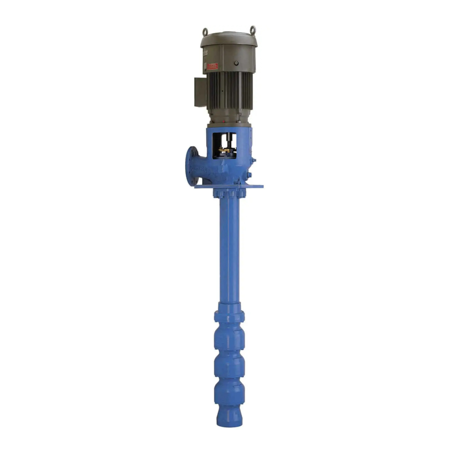
- Page 1 INSTRUCTION MANUAL IOMGWDWTR02 MODEL DWT DEEP WELL TURBINE PUMPS INSTALLATION, OPERATION AND MAINTENANCE INSTRUCTIONS...
- Page 2 The design, materials, and workmanship incorporated in the construction of the Goulds Water Technology DWT Pumps makes them capable of giving long, trouble-free service. The life and satisfactory service of any mechanical unit, however, is enhanced and extended by correct application, proper installation, periodic inspection, condition monitoring and careful maintenance.
-
Page 3: Table Of Contents
Table of Contents SUBJECT PAGE Safety ..................................4 Safety Instructions ..............................4 General Precautions ..............................4 General Information ..............................4 Introduction ................................4 Receiving and Checking ............................4 Materials and Equipment Required ........................... 5 Storage ..................................5 General Description ..............................6 Installation .................................. -
Page 4: Safety
Warns of hazards that CAN cause personal CAUTION injury or property damage. The design, material, and workmanship incorporated in the construction of Goulds Water Technology DWT NOTICE: INDICATES SPECIAL INSTRUCTIONS pumps makes them capable of giving long, trouble WHICH ARE VERY IMPORTANT AND MUST BE free service. -
Page 5: Materials And Equipment Required
This section is intended to be of general assistance to users of Goulds Water Technology DWT pumps. It shall not modify, amend and/or otherwise alter the scope of Goulds Water Technology DWT pumps warranty... -
Page 6: General Description
If the pump is assembled, place an additional one pound (0.5 kg) in the discharge When the DWT pump is to be installed in a well, nozzle securely fastened to the discharge elbow. consideration must be given to the well before installation. - Page 7 DISCHARGE HEAD ASSEMBLY ITEM DESCRIPTION HEADSHAFT ADJUSTING NUT GIB KEY SLINGER DISCHARGE HEAD STUFFING BOX BEARING STUFFING BOX STUFFING BOX GASKET SPLIT GLAND GLAND ADJUSTING NUT PACKING COLUMN FLANGE COLUMN ASSEMBLY COLUMN NIPPLE COLUMN COUPLING COULMN PIPE LINESHAFT LINESHAFT SLEEVE BEARING RETAINER LINESHAFT BEARING LINESHAFT COUPLING...
- Page 8 HEAD ASSEMBLY ITEM DESCRIPTION HEADSHAFT ADJUSTING NUT GIB KEY DISCHARGE HEAD OIL RESERVOIR TENSION NUT TENSION PLATE TENSION PLATE GASKET O’RING COLUMN FLANGE COLUMN ASSEMBLY COLUMN LOCK RING COLUMN NIPPLE COLUMN COUPLING COLUMN PIPE TUBE NIPPLE OIL TUBE TUBE STABLIZER LINESHAFT LINESHAFT SLEEVE LINESHAFT BEARING...
- Page 9 HEAD ASSEMBLY ITEM DESCRIPTION HEADSHAFT ADJUSTING NUT GIB KEY DISCHARGE HEAD OIL RESERVOIR TENSION NUT TENSION PLATE TENSION PLATE GASKET O’RING COLUMN FLANGE COLUMN, OIL TUBE AND LINESHAFT ASSEMBLY COLUMN LOCK RING COLUMN NIPPLE COLUMN COUPLING COLUMN PIPE TUBE NIPPLE OIL TUBE TUBE RETAINER LINESHAFT...
-
Page 10: Foundation / Piping
5. Carefully lower the sub base onto the foundation FOUNDATION AND PIPING bolts. Hand tightens the nuts. SUB BASE (SOLE PLATE) INSPECTION 6. Leveling the sub base may be done by several Sub base and sole plate are terms in common use to methods. -
Page 11: Installing The Bowl Assembly
Never draw piping into place by forcing 3. Place two I-beam supports across the base plate WARNING the flange connections of the pump. Pipe opening, strong enough to safely support the weight strain will adversely effect the operation of the pump of the entire pump assembly. -
Page 12: Installing The Column
INSTALLING THE COLUMN 4. For threaded column, secure a friction clamp immediately below the column coupling. Hoist OPEN LINESHAFT column section over bowl assembly. Lower column over lineshaft until column pipe engages Lineshafts are coupled with threaded or keyed couplings. the discharge bowl. -
Page 13: Installing The Discharge Head
INSTALLING THE DISCHARGE HEAD of the tube section rests on the adapter bearing DWT Pumps are provided with either a cast iron or fab (668). The end faces of the tube should be clean steel type head. Install the discharge head as follows: and free of nicks. -
Page 14: Installing The Stuffing Box
3. Remove coupling guard if provided. Attach a sling 7. Hoist the discharge head by lifting lug and remove to the lifting lugs on the side of the discharge head the elevator clamp attached to column. through windows and hoist discharge head over the protruding top shaft (or stub shaft). -
Page 15: Installing The Tension Plate
6. Install the split gland and screw nuts on the split 9. A properly packed stuffing box should be loose gland studs. Tighten nuts then relieve the nuts and enough to allow the shaft to be turned manually. tighten finger tight. If discharge pressure is over 100 PSI, attach bypass line to the stuffing box bypass. -
Page 16: Installing The Driver
2. Clean the surface of the discharge head where the are found, remove burrs with a smooth mill file, tension plate will be mounted and remove any nicks cleaning thoroughly afterward. or burrs with a fine flat file. Clean the O.D. of the 4. - Page 17 Never check motor rotation with the drive NOTE: 1.00" and 1.18" diameter shafts are 12 thread CAUTION coupling in place. The bore clearance per inch (tpi), 1.50" through 2.44" are 10 tpi, all between the drive coupling and the pump shaft O.D. larger sizes are 8 tpi.
-
Page 18: Pump Startup And Operation
Pump Startup And Operation Pump Startup And Operation 4. For oil lubricated pump, clean and fill the lubricator tank with recommended oil. (See pages 19 and 20.) PRE-START PROCEDURE Manually open the lubricator valve and allow oil to run into the shaft enclosing tube for at least 20 Consult the applicable manufacturer’s instructions for minutes for each 100 feet (30 meters) of setting detailed information for the prime mover (electric motor,... -
Page 19: Preventive Maintenance
5. For open lineshaft pumps, with the pump in 2. With the pump shut down and when packing has operation, there should be some leakage at the been compressed to the point that the gland is about stuffing box packing. The correct leakage rate is to contact the upper face of stuffing box, remove the approximately one drop per second. -
Page 20: Preventive Maintenance Schedule
PREVENTIVE MAINTENANCE SCHEDULE TIME INTERVAL PROCEDURE (in operating hours) Clean dirt, oil and grease from driver and discharge head. As required. Clean driver ventilation passage to prevent overheating. As required. Change lubrication in gear drive. 2,000 or once a year Check oil level in the reservoir. - Page 21 Manufacturer Recommended Food Machinery Lubricants Chevron Chevron #FM Grease EP2 *#Lubricating Oil FM32 Chevron Texaco Corp. Texaco Texaco #Cygnus Grease 2 #Cygnus Hydraulic Oil 32 Mystik Oil & Grease Mystik Oil & Grease #Mystik FG2 Grease (5607) #Mystik FG/AW 32 Oil (1931) Citgo Oil &...
-
Page 22: Troubleshooting
TROUBLESHOOTING TROUBLE PROBABLE CAUSE REMEDY 1. Pump does not start A. Electrical circuit open or not Check circuit and correct. completed B. Improper lateral adjustment. Reset impeller adjustment, Impeller on bottom. See page 16. C. Low voltage supplied to Check whether driver wiring is electric driver correct and receives full voltage. - Page 23 TROUBLESHOOTING TROUBLE PROBABLE CAUSE REMEDY 6. Pump takes too much A. Damaged impeller Inspect, replace if damaged. power B. Foreign object lodged between Remove object as required. impeller and bowl C. Specific gravity higher than Test liquid for viscosity and pump designed for specific gravity. D. Viscosity too high, partial Check for both. They can cause freezing of pumpage drag on impeller.
-
Page 24: Disassembly And Reassembly
Disassembly And Reassembly Disassembly And Reassembly SHAFT DISASSEMBLY Before working on pump or motor, lock WARNING out driver power to prevent accidental TAPERLOCK DRIVER startup and physical injury. DISASSEMBLY POSITION NOTE: Pump components should be match-marked prior to disassembly to ensure they are reassembled in the correct location. -
Page 25: Inspection And Reassemble
INSPECTION AND REASSEMBLY Wear protective gloves and use WARNING appropriate eye protection to prevent INSPECTION AND REPLACEMENT injury when handling hot parts. 1. Clean all pump parts thoroughly with a suitable cleaner. 2. Check bearing retainers for deformation and wear. 3. -
Page 26: Repair Parts
6. Hold impeller firmly against the suction bowl/bell Repair Parts and drive the taperlock into place with a taperlock ORDERING PARTS driver, (See Figure 14). After the impeller is secured in position, the top end of the taperlock should be When ordering spare or replacement parts, the pump 1/8”... -
Page 28: Limited Warranty
IN NO EVENT SHALL COMPANY BE LIABLE IN EXCESS OF THE SALES PRICE OF THE PART OR PRODUCT FOUND DEFECTIVE. Xylem Inc. PO Box 5487 Lubbock, TX 79408 Phone: 1-806-763-7867 Fax: 1-800-453-4749 www.gouldswatertechnology.com Goulds is a registered trademark of Goulds Pumps, Inc. and is used under license. © 2017 Xylem Inc. IOMGWDWTR02 August 2017...
Need help?
Do you have a question about the DWT and is the answer not in the manual?
Questions and answers