Goulds Pumps VIT Installation, Operation And Maintenance Instructions
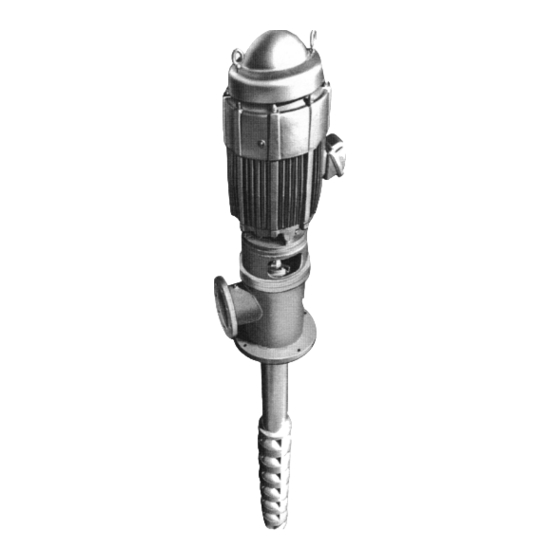
Vertical industrial turbine pumps
Hide thumbs
Also See for VIT:
- Installation, operation and maintenance manual (82 pages) ,
- Installation, operation and maintenance manual (110 pages)

Related Manuals for Goulds Pumps VIT


Summary of Contents for Goulds Pumps VIT
- Page 1 INSTRUCTION MANUAL IOMGWVITR02 MODEL VIT VERTICAL INDUSTRIAL TURBINE PUMPS INSTALLATION, OPERATION AND MAINTENANCE INSTRUCTIONS...
- Page 2 The design, materials and workmanship incorporated in the construction of the Goulds Water Technology VIT Pumps makes them capable of giving long, trouble-free service. The life and satisfactory service of any mechanical unit, however, is enhanced and extended by correct application, proper installation, periodic inspection, condition monitoring and careful maintenance.
-
Page 3: Table Of Contents
Table of Contents Table of Contents SUBJECT PAGE SECTION 1 – Safety ..............................4 Safety Instructions ..............................4 General Precautions ..............................4 SECTION 2 – General Information ..........................4 Introduction ................................4 Receiving and Checking ............................4 Materials and Equipment Required ........................... 5 Storage .................................. -
Page 4: Section 1 - Safety
Warns of hazards that CAN cause personal CAUTION injury or property damage. The design, material, and workmanship incorporated in the construction of Goulds Water Technology VIT NOTICE: INDICATES SPECIAL INSTRUCTIONS Pumps makes them capable of giving long, trouble WHICH ARE VERY IMPORTANT AND MUST BE free service. -
Page 5: Materials And Equipment Required
This section is intended to be of general assistance to users of Goulds Water Technology VIT Pumps. It shall not modify, amend and/or otherwise alter the scope of Goulds Water Technology VIT Pumps warranty... -
Page 6: General Description
Impellers may be either open or enclosed depending on GENERAL DESCRIPTION the design requirements. They are fastened to the pump The model VIT pump is a vertical turbine lineshaft shaft by taperlocks. For temperatures over 140º F pump, which is designed to meet wide ranges of service (60º... -
Page 7: Typical Drawings
DISCHARGE HEAD ASSEMBLY ITEM DESCRIPTION DISCHARGE HEAD MOTOR SUPPORT HEADSHAFT COUPLING ASSEMBLY SEAL HOUSING SEAL HOUSING BEARING MECHANICAL SEAL COLUMN FLANGE SEAL HOUSING GASKET COLUMN ASSEMBLY COLUMN PIPE COLUMN COUPLING LINESHAFT LINESHAFT COUPLING BEARING RETAINER LINESHAFT BEARING BOWL ASSEMBLY BOWL SHAFT DISCHARGE BOWL DISCHARGE BEARING INTERMEDIATE BOWL... - Page 8 DISCHARGE HEAD ASSEMBLY ITEM DESCRIPTION DISCHARGE HEAD HEADSHAFT COUPLING ASSEMBLY SEAL HOUSING SEAL HOUSING BEARING MECHANICAL SEAL COLUMN ASSEMBLY COLUMN PIPE COLUMN BOLTING LINESHAFT LINESHAFT COUPLING BEARING RETAINER LINESHAFT BEARING BOWL ASSEMBLY BOWL SHAFT INTERMEDIATE BOWL INTERMEDIATE BOWL BEARING IMPELLER TAPERLOCK WEAR RING (OPTIONAL) HEX BOLT...
- Page 9 HEAD ASSEMBLY ITEM DESCRIPTION DISCHARGE HEAD ADJUSTING NUT HEADSHAFT O-RING TENSION PLATE TENSION NUT OILER COLUMN FLANGE GIB KEY TENSION PLATE GASKET COLUMN ASSEMBLY TUBE NIPPLE COLUMN NIPPLE COLUMN LOCK RING COLUMN PIPE COLUMN COUPLING LINESHAFT LINESHAFT COUPLING OIL TUBE LINESHAFT BEARING TUBE STABILIZER BOWL ASSEMBLY...
- Page 10 HEAD ASSEMBLY ITEM DESCRIPTION DISCHARGE HEAD ADJUSTING NUT HEADSHAFT O-RING TENSION PLATE TENSION NUT OIL RESERVOIR COLUMN FLANGE GIB KEY TENSION PLATE GASKET COLUMN ASSEMBLY TUBE NIPPLE COLUMN PIPE COLUMN BOLTING LINESHAFT LINESHAFT COUPLING OIL TUBE LINESHAFT BEARING TUBE STABLIZER BOWL ASSEMBLY BOWL SHAFT DISCHARGE BOWL...
-
Page 11: Section 3 - Installation
Installation – SECTION 3 Installation – SECTION 3 5. Carefully lower the sub base onto the foundation bolts. Hand tighten the nuts. FOUNDATION AND PIPING 6. Leveling the sub base may be done by several SUB BASE (SOLE PLATE) INSPECTION methods. -
Page 12: Pump Installation
9 Sylvan Way, Parsippany, NJ 07054-3802 and must be to lower unit until the discharge head flange engages reviewed prior to pump installation. and rests firmly on the plate, then secure with capscrews provided. Never draw piping into place by forcing WARNING 5. -
Page 13: Installing The Column
6. Attach a sling to the elevator clamps, eyebolts, With a keyed coupling or lifting bail and hoist it into position over the insert the key into the foundation opening. (See Figure 7). pump shaft. Lower the sleeve over the pump shaft, 7. - Page 14 10. Install the top shaft or stub shaft and coupling. If 7. With lineshaft in proper position on the coupling, the pump is equipped with column adjusting nipple, remove tail rope and screw lineshaft into coupling install it with longer threaded end upward. Screw until resistance is felt.
-
Page 15: Installing The Discharge Head
INSTALLING THE DISCHARGE HEAD INSTALLING THE STUFFING BOX VIT Pumps are provided with either a cast iron or fabricated steel type head. For pump with below Assemble stuffing box as shown in Figure 9. ground discharge, a motor stand is provided instead the 1. -
Page 16: Installing The Mechanical Seal
7. The stuffing box is shipped with both ports plugged. 7. Install the O-ring or gasket, between the seal If the discharge pressure is over 100 psi, remove the housing and seal. Install the seal over the shaft and plug on Port “A” and attach a bypass (relief) line. If ease it into position against the face of the seal box. -
Page 17: Installing The Tension Plate
FLATNESS OF THE SEAL HOUSING CONCENTRICITY OF MOTOR SHAFT USING JACKSCREWS For this measurement, remove the mechanical seal if the dial indicator stylus cannot rotate 360° on the top surface 1. Install the dial indicator of the seal gland. as shown, with the base attached to the motor 1. - Page 18 NOTE: Do not turn clockwise to align holes in tension DIRECT PULL METHOD plate and discharge head. 1. The upper end of the tube may be pulled by the hoist to obtain the predetermined tension value. INSTALLING TENSION NUT This requires the use of a dynamometer scale and 1.
-
Page 19: Installing The Driver
the input shaft to the desired position. Align the driver mounting holes with the mating tapped holes on the discharge head. Lower the driver until the registers engage and the driver rests on the discharge LUBE LINE TENSION NUT (635) head. - Page 20 2. Align hole “A” in the (604) ADJUSTING NUT 11. Install motor drive coupling. (Be sure to line up the match mark made at step 6.) Inserting the ratchet adjusting nut (604) and pins if a non-reverse ratchet is used. Match the hole “C”...
- Page 21 3. Orient the motor conduit box in the required position. Align the motor mounting holes with the mating tapped holes on the discharge head. Lower the motor until the registers engage and the motor rests on the discharge head. Secure motor with capscrews provided.
-
Page 22: Installing The Thrust Pot
IMPELLER ADJUSTMENT Impeller adjustment is identical for all motors and right angle gear drives. Adjustment is accomplished by turning the adjusting plate (613). (See Figure 16 or 17). The correct adjustment is listed on the Outline Drawing for the specific unit. If the pump has a thrust pot, do not adjust the impeller position until the thrust pot has been installed and adjust the impeller position by using the adjust nut on the thrust pot. - Page 23 INSTALLING THE OIL LUBRICATED THRUST POT INSTALLATION: If the unit is supplied with a thrust pot (see Figure 19), 1. Install both coupling halves prior to mounting the thrust pot should be installed on top of the discharge the motor. Refer to the coupling manufacturer’s instructions.
-
Page 24: Section 4 - Pump Start Up And Operation
9. Install the bottom of the flexible coupling to the top B. Driver must rotate counterclockwise (CCW) of the drive shaft. when viewed from above. Do not check motor rotation unless motor WARNING 10. Attach a sling to the lifting lugs of driver and hoist is bolted to pump and drive coupling is the driver up. - Page 25 2. For open lineshaft pump, make sure the stuffing PUMP STARTUP box relief (bleed) line is connected (if applicable). For enclosed lineshaft pump, make sure the oil 1. Partially close the valve in the discharge line. lubrication piping is connected and oil reservoir filled with the recommended oil.
-
Page 26: Section 5 - Maintenance
Maintenance – SECTION 5 Maintenance – SECTION 5 It may be necessary to repeat this procedure several times before proper amount of liquid comes through to PREVENTIVE MAINTENANCE efficiently prevent overheating. If leakage is excessive, adjust the stuffing box as follows: Before initiating maintenance procedures, WARNING disconnect all electric sources to the... -
Page 27: Thrust Pot Lubrication And Maintenance
THRUST POT LUBRICATION AND MAINTENANCE The bearing is pre-lubricated at factory. Re-grease the bearing according the following procedure and per the OIL LUBRICATED THRUST POT (SEE FIGURE 19) schedule in the above table. Following are the re-grease procedure: Pumps are shipped without oil. Oil- WARNING lubricated bearings must be lubricated at 1. -
Page 28: Recommended Lubricants
RECOMMENDED LUBRICANTS Grease for Lineshafts, Turbine oils for Lineshafts, Suction Bowl Bearings Suction Bowl Bearings and Shaft Packings and similar applications Operating Temperature Range 20º F to 120º F 20º F to 120º F Required properties Pour Point : 20º F or lower (base oil) 20º... -
Page 29: Troubleshooting
TROUBLESHOOTING TROUBLE PROBABLE CAUSE REMEDY 1. Pump does not start A. Electrical circuit open or not Check circuit and correct. completed B. Improper lateral adjustment. Reset impeller adjustment, Impeller on bottom. See pages 19 or 21. C. Low voltage supplied to Check whether driver wiring is electric driver correct and receiving full voltage. - Page 30 TROUBLESHOOTING TROUBLE PROBABLE CAUSE REMEDY 6. Pump takes too much A. Damaged impeller Inspect, replace if damaged. power B. Foreign object lodged between Remove object as required. impeller and bowl C. Specific gravity higher than Test liquid for viscosity and pump designed for specific gravity. D. Viscosity too high, partial Check for both. They can cause freezing of pumpage drag on impeller.
-
Page 31: Section 6 - Disassembly And Reassembly
Disassembly and Reassembly – SECTION 6 Disassembly and Reassembly – SECTION 6 SHAFT DISASSEMBLY Before working on pump or motor, lock WARNING out driver power to prevent accidental TAPERLOCK DRIVER startup and physical injury. DISASSEMBLY POSITION NOTE: Pump components should be match-marked prior to disassembly to ensure they are reassembled in the correct location. -
Page 32: Inspection And Reassembly
IMPELLER WEAR RING REMOVAL REASSEMBLY OF THE BOWL ASSEMBLY WITH TAPERLOCK CONSTRUCTION 1. Utilizing a diamond point chisel, cut two “V” shaped 1. For ease in reassembly apply a thin film of turbine grooves on the impeller wear ring approximately oil to all mating and threaded parts. - Page 33 3. Hold the shaft in this position by inserting a long FINAL ASSEMBLY capscrew (or all thread rod with a hex nut) with an After reassembling the bowl assembly, see Section 3 for assembly jig into the bottom end of the suction hub installation.
-
Page 34: Section 7 - Repair Parts
Repair Parts – SECTION 7 Repair Parts – SECTION 7 ORDERING PARTS When ordering spare or replacement parts, the pump serial number and size and type of pump must be given. This can be found on the nameplate furnished with the unit. - Page 35 NOTES...
-
Page 36: Limited Warranty
OF PRODUCTION, LOSS OF OPPORTUNITY OR LOSS OF REPUTATION. Xylem Inc. PO Box 5487 Lubbock, TX 79408 Phone: 1-806-763-7867 Fax: 1-800-453-4749 www.gouldswatertechnology.com Goulds is a registered trademark of Goulds Pumps, Inc. and is used under license. © 2017 Xylem Inc. IOMGWVITR02 August 2017...
Need help?
Do you have a question about the VIT and is the answer not in the manual?
Questions and answers