Table of Contents
Advertisement
Quick Links
Advertisement
Table of Contents

Subscribe to Our Youtube Channel
Related Manuals for Goulds Pumps ITT ICB


Summary of Contents for Goulds Pumps ITT ICB
- Page 1 Installation, Operation and Maintenance Instruction...
-
Page 3: Table Of Contents
Table of Contents Table of Contents 1 Introduction and Safety ............................ 4 1.1 Introduction..............................4 1.1.1 Requesting other information ......................4 1.1.2 Standard manufacturer ........................4 1.2 Safety ................................ 4 1.2.1 Safety terminology and symbols ..................... 5 1.2.2 Environmental safety........................6 1.2.3 User safety ............................ - Page 4 Table of Contents 5 Commissioning, Startup, Operation, and Shutdown ................... 41 5.1 Preparation for startup..........................41 5.2 Check the rotation ..........................42 5.3 Shaft-sealing options..........................42 5.3.1 Mechanical seal options........................ 43 5.3.2 Connection of sealing liquid for mechanical seals ................ 43 5.4 Pump priming ............................
- Page 5 Table of Contents 9.1 Putting pump out of operation ......................... 67 9.2 Disposal..............................67 10 Certificates ..............................68 10.1 Declaration of no objection........................68 10.2 Declarations of conformity and incorporation ..................69 11 Other Relevant Documentation or Manuals ....................73 11.1 For additional documentation ........................
-
Page 6: Introduction And Safety
1 Introduction and Safety 1 Introduction and Safety 1.1 Introduction Purpose of this manual The purpose of this manual is to provide necessary information for: • Installation • Operation • Maintenance CAUTION: Failure to observe the instructions contained in this manual could result in personal injury and/or property damage, and may void the warranty. -
Page 7: Safety Terminology And Symbols
1.2 Safety • The operator must be aware of the pumpage and take appropriate safety precautions to prevent physical injury. • Risk of serious injury or death. If any pressure-containing device is over-pressurized, it can explode, rupture, or discharge its contents. It is critical to take all necessary meas- ures to avoid over-pressurization. -
Page 8: Environmental Safety
1.2 Safety Hazard level Indication CAUTION: A hazardous situation which, if not avoided, could result in minor or moderate injury NOTICE: • A potential situation which, if not avoided, could result in unde- sirable conditions • A practice not related to personal injury Hazard categories Hazard categories can either fall under hazard levels or let specific symbols replace the ordinary hazard level symbols. -
Page 9: User Safety
1.2 Safety WARNING: If the product has been contaminated in any way, such as from toxic chemicals or nuclear radi- ation, do NOT send the product to ITT until it has been properly decontaminated and advise ITT of these conditions before returning. Electrical installation For electrical installation recycling requirements, consult your local electric utility. - Page 10 1.2 Safety Personnel should wear appropriate hearing protection when working on or around any equip- ment, including pumps. Consider limiting personnel’s exposure time to noise or, where possi- ble, enclosing equipment to reduce noise. Local law may provide specific guidance regarding exposure of personnel to noise and when noise exposure reduction is required.
-
Page 11: Hazardous Liquids
1.3 Product warranty • Do not open any vent or drain valve or remove any plugs while the system is pressurized. Make sure that the pump is isolated from the system and that pressure is relieved before you disassem- ble the pump, remove plugs, or disconnect piping. 1.2.4 Hazardous liquids The product is designed for use in liquids that can be hazardous to your health. -
Page 12: Ex Considerations And Intended Use
1.4 Ex Considerations and Intended Use • Bodily injuries • Material damages • Economic losses Warranty claim ITT products are high-quality products with expected reliable operation and long life. However, should the need arise for a warranty claim, then contact your ProCast representative. Ex Considerations and Intended Use Special care must be taken in potentially explosive environments to ensure that the equipment is proper- ly maintained. - Page 13 1.4 Ex Considerations and Intended Use • Potential electrostatic charging hazard. Do not rub, clean, or blast equipment with dry cloth or dry media. • Before you start work on the product, make sure that the product and the control panel are isolated from the power supply and the control circuit, so they cannot be energized.
- Page 14 Maintenance manual (IOM) can cause serious personal injury or damage to the equipment. This in- cludes any modification to the equipment or use of parts not provided by ITT Goulds Pumps. If there is any question regarding the intended use of the equipment, please contact an ITT Goulds representative before proceeding.
- Page 15 1.4 Ex Considerations and Intended Use The code classification marked on the equipment must be in accordance with the specified area where the equipment will be installed. If it is not, do not operate the equipment and contact your ITT Goulds Pumps sales representative before proceeding.
- Page 16 1.4 Ex Considerations and Intended Use • Pumps must be fully primed at all times during operation. • The preventive maintenance section must be adhered to in order to keep the applicable Ex classification of the equipment. Failure to follow these procedures will void the Ex clas- sification for the equipment.
- Page 17 1.4 Ex Considerations and Intended Use • In plants or pumps with cathodic corrosion protection, a small current constantly flows through the construction. This is not permissible on the complete pump or partially-as- sembled machinery without further precautions being taken. ITT should be consulted in this context.
-
Page 18: Transportation And Storage
2 Transportation and Storage 2 Transportation and Storage 2.1 Inspect the delivery 2.1.1 Inspect the package Inspect the package for damaged or missing items upon delivery. Note any damaged or missing items on the receipt and freight bill. File a claim with the shipping company if anything is out of order. If the product has been picked up at a distributor, make a claim directly to the distributor. - Page 19 2.2 Transportation guidelines Precautions for lifting the pump WARNING: • Dropping, rolling or tipping units, or applying other shock loads, can cause property dam- age and/or personal injury. Ensure that the unit is properly supported and secure during lifting and handling. •...
-
Page 20: Storage Guidelines
2.3 Storage guidelines 2.3 Storage guidelines 2.3.1 Short-term storage Storage requirements short-term (less than six month). Store in a covered and dry location. 2.3.2 Long-term storage If the unit is stored for more than 6 months, these requirements apply: • Store in a covered and dry location. -
Page 21: Product Description
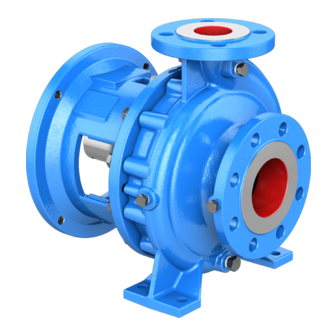
3 Product Description 3 Product Description 3.1 General description ICB pumps are single-stage volute casing pumps in block design. Hydraulic design and dimensions com- ply with ISO 2858/ EN 22858, the technical design complies with ISO 5199/EN 25199. The motors comply with DIN 42677-IM B5. Motor and pump shaft are coupled rigidly. The permitted application conditions and design details of the delivered pump are shown in the attached data sheet and / or the order confirmation. -
Page 22: Nameplate Information
3.2 Nameplate information 3.2 Nameplate information Pump nameplate Figure 4: Pump nameplate Nameplate Field Explanation Serial number of the pump MODEL Pump Model SIZE Size of Pump STD DIM ANSI Std designation – Not applicable ISO Pumps HYDRO PRESS Pump Test Pressure in kPag FLOW Rated pump flow in cubic metres per hour Rated pump speed in revolutions per minute... -
Page 23: Installation
4 Installation 4 Installation 4.1 Pre-installation Precautions WARNING: • When installing in a potentially explosive environment, ensure that the motor is properly certified. • All equipment being installed must be properly grounded to prevent unexpected dis- charge. Discharge can cause equipment damage, electric shock, and result in serious in- jury. -
Page 24: Foundation Requirements
4.1 Pre-installation Guideline Explanation/comment Do not install and operate the equipment in closed Acceptable devices: systems unless the system is constructed with • Pressure relief valves properly-sized safety devices and control devices. • Compression tanks • Pressure controls • Temperature controls •... -
Page 25: Baseplate-Mounting Procedures
4.2 Baseplate-mounting procedures J-type bolts Item Description Baseplate Shims or wedges Foundation Bolt Figure 6: J-type bolts 4.2 Baseplate-mounting procedures 4.2.1 Prepare the baseplate for mounting Remove all the attached equipment from the baseplate. Clean the underside of the baseplate completely. If applicable, coat the underside of the baseplate with an epoxy primer. -
Page 26: Install The Baseplate Using Shims Or Wedges
4.2 Baseplate-mounting procedures 4.2.3 Install the baseplate using shims or wedges Required tools: • Two sets of shims or wedges for each foundation bolt • Two machinist's levels • Baseplate-leveling worksheet This procedure is applicable to cast iron and fabricated steel baseplates. If you use sleeve-type bolts, fill the bolt sleeves with packing material or rags to prevent grout from entering the bolt holes. - Page 27 4.2 Baseplate-mounting procedures • Two machinist's levels • Baseplate-leveling worksheet This procedure is applicable to the feature-fabricated steel baseplate and the advantage base baseplate. Apply an anti-seize compound on the jackscrews. The compound makes it easier to remove the screws after you grout. Lower the baseplate carefully onto the foundation bolts and perform these steps: Cut the plates from the bar stock and chamfer the edges of the plates in order to reduce stress concentrations.
- Page 28 4.2 Baseplate-mounting procedures Item Description Machinist's levels Driver's mounting pads Foundation bolts Jackscrews Grout hole Pump's mounting pads Figure 10: Level driver mounting pads Turn the center jackscrews down so that they rest on their plates on the foundation surface. Level the pump mounting pads: NOTICE: Remove all dirt from the mounting pads in order to ensure that the correct leveling is achieved.
-
Page 29: Install The Baseplate Using Spring Mounting
4.2 Baseplate-mounting procedures Check that the driver's mounting pads are level and adjust the jackscrews and the foundation bolts if necessary. The correct level measurement is a maximum of 0.167 mm/m | 0.002 in./ft . 4.2.5 Install the baseplate using spring mounting NOTICE: The spring-mounted baseplate is designed only to support piping loads from thermal expan- sion. -
Page 30: Install The Baseplate Using Stilt Mounting
4.2 Baseplate-mounting procedures Upper jam nut Follower Washer Foundation pads Spring Upper adjusting nut Spring stud Figure 12: Example of an installed spring assembly 4.2.6 Install the baseplate using stilt mounting NOTICE: The stilt-mounted baseplate is not designed to support static piping loads. Ensure that the suc- tion and discharge piping are supported individually. - Page 31 4.2 Baseplate-mounting procedures Lower the baseplate so that the stilts fit into the foundation cups. Level the baseplate and make the final height adjustments: Loosen the upper jam nuts and adjusting nuts. Adjust the height and level the baseplate by moving the lower adjusting nuts. When the baseplate is level, tighten the top adjusting nuts.
-
Page 32: Baseplate-Leveling Worksheet
4.2 Baseplate-mounting procedures 4.2.7 Baseplate-leveling worksheet Level measurements 1)____________________ 2)____________________ 3)____________________ 4)____________________ 5)____________________ 6)____________________ 7)____________________ 8)____________________ 9)____________________ 10)___________________ 11)___________________ 12)___________________ 13)___________________ 14)___________________ 15)___________________ 16)___________________ 17)___________________ 18)___________________ ICB Installation, Operation and Maintenance Instruction... -
Page 33: Grout The Baseplate
4.3 Grout the baseplate 4.3 Grout the baseplate Required equipment: • Cleaners: Do not use an oil-based cleaner because the grout will not bond to it. See the instructions provided by the grout manufacturer. • Grout: Non-shrink grout is recommended. NOTICE: It is assumed that the installer who grouts the baseplate has knowledge of acceptable meth- ods. -
Page 34: Piping Checklists
4.4 Piping checklists Item Description Baseplate Grout Foundation Bolt Figure 15: Fill remainder of baseplate with grout Remove the leveling jackscrews after the grout hardens in order to remove any stress points. Tighten the foundation bolts. Make sure that treatment of the concrete is in accordance with DIN 1045. 4.4 Piping checklists 4.4.1 General piping checklist Precautions... - Page 35 4.4 Piping checklists NOTICE: Vary the capacity with the regulating valve in the discharge line. Never throttle the flow from the suction side. This action can result in decreased performance, unexpected heat generation, and equipment damage. Piping guidelines Guidelines for piping are given in the Hydraulic Institute Standards available from the Hydraulic Institute at 9 Sylvan Way, Parsippany, NJ 07054-3802.
-
Page 36: Permitted Nozzle Loads And Torques At The Pump Nozzles
4.4 Piping checklists Check Explanation/comment Checked Use cushioning devices. This protects the pump from surges and water hammer if quick-closing valves are installed in the system. In no case should loads on the pump Bottom of casing should be supported by a solid foundation or flanges exceed the limits stated in casing feet should be used. -
Page 37: Suction-Piping Checklist
4.4 Piping checklists Figure 16: Permitted Nozzle loads and torques at pump Nozzle Forces in N Torques in Nm Forces in N Torques in Nm ∅DN ∅DN ∑F ∑M ∑F ∑M Suction nozzle Discharge nozzle 560 1100 730 590 1070 760 1450 780 650 1150 1180 1040 950 1850 840... - Page 38 4.4 Piping checklists Suction-piping checks Check Explanation/comment Checked Check that the distance between the inlet This minimizes the risk of cavitation in the suction in- flange of the pump and the closest elbow let of the pump due to turbulence. is at least five pipe diameters.
- Page 39 4.4 Piping checklists Liquid source above the pump Check Explanation/comment Checked Check that an isolation valve is installed in This permits you to close the line during pump inspec- the suction piping at a distance of at least tion and maintenance. two times the pipe diameter from the suc- Do not use the isolation valve to throttle the pump.
-
Page 40: Discharge Piping Checklist
4.4 Piping checklists Example: Suction piping equipment Correct Incorrect Suction pipe sloping upwards from liquid source Air pocket, because the eccentric reducer is not used and because the suction piping does not Long-radius elbow slope gradually upward from the liquid source Strainer Foot valve Eccentric reducer with a level top... -
Page 41: Bypass-Piping Considerations
4.4 Piping checklists Example: Discharge piping equipment Correct Incorrect Check valve (incorrect position) Bypass line The isolation valve should not be positioned be- Shut-off valve tween the check valve and the pump. Check valve Discharge isolation valve 4.4.5 Bypass-piping considerations When to use a bypass line Provide a bypass line for systems that require operation at reduced flows for prolonged periods. -
Page 42: Final Piping Checklist
4.4 Piping checklists NOTICE: • Auxiliary cooling and flush systems must be operating properly to prevent excess heat generation, sparks, and/or premature failure. Ensure auxiliary piping is installed as specified on the pump data sheet prior to startup. • Make sure that the ignition temperature of the cooling liquid is at least 50 K higher than the surface temperature of the bearing frame, if the pump is used in potentially explosive environment. -
Page 43: Commissioning, Startup, Operation, And Shutdown
5 Commissioning, Startup, Operation, and Shutdown 5 Commissioning, Startup, Operation, and Shutdown 5.1 Preparation for startup WARNING: • Risk of serious physical injury or death. Exceeding any of the pump operating limits (e.g. - pressure, temperature, power, etc.) could result in equipment failure, such as explosion, seizure, or breach of containment. -
Page 44: Check The Rotation
5.2 Check the rotation • Flush and clean the system thoroughly to remove dirt or debris in the pipe system in order to prevent premature failure at initial startup. • Bring variable-speed drivers to the rated speed as quickly as possible. •... -
Page 45: Mechanical Seal Options
5.4 Pump priming • Conventional outside-component mechanical seal 5.3.1 Mechanical seal options Pumps are usually shipped with mechanical seals installed. If they are not, then refer to the mechanical seal manufacturer's installation instructions. These are the mechanical seal options for this pump: •... -
Page 46: Prime The Pump With The Suction Supply Below The Pump
5.4 Pump priming Item Description Discharge isolation valve Check valve Suction isolation valve Figure 17: Suction supply above pump 5.4.2 Prime the pump with the suction supply below the pump Use a foot valve and an outside source of liquid in order to prime the pump. The liquid can come from one of these sources: •... -
Page 47: Other Methods Of Priming The Pump
5.5 Start the pump Item Description By-pass line Item Description Shutoff valve Discharge isolation valve Foot valve Shutoff valve Check valve From outside supply Discharge isolation valve Foot valve Check valve Figure 19: Pump priming with suction supply below pump with foot valve using bypass Figure 18: Pump priming with suction supply around check valve below pump with foot valve and an outside sup-... -
Page 48: Pump Operation Precautions
5.6 Pump operation precautions NOTICE: • Risk of equipment damage due to dry operation. Immediately observe the pressure gauges. If discharge pressure is not quickly attained, stop the driver immediately, reprime, and attempt to restart the pump. Fully close the discharge valve, depending on system conditions. Start the driver. -
Page 49: Inadmissible Modes Of Operations And Their Consequences (Examples)
5.7 Inadmissible modes of operations and their consequences (examples) Operation at reduced capacity WARNING: • Risk of breach of containment and equipment damage. Excessive vibration levels can cause damage to bearings, seal chamber, and/or mechanical seal. Observe pump for vi- bration levels, bearing temperature, and excessive noise. -
Page 50: Abrasive Media
5.8 Abrasive Media • Pump may be destroyed due to overheating. Discharge valve closed too much: • Pump may be destroyed due to overheating. • Axial thrust too great. Discharge valve opened too much: • Pump can cavitate. Particularly severe with an empty discharge line. •... -
Page 51: Maintenance
6 Maintenance 6 Maintenance 6.1 Maintenance schedule Maintenance inspections A maintenance schedule includes these types of inspections: • Routine maintenance • Routine inspections • Three-month inspections • Annual inspections Shorten the inspection intervals appropriately if the pumped fluid is abrasive or corrosive or if the envi- ronment is classified as potentially explosive. -
Page 52: Shaft Seal Maintenance
6.2 Shaft seal maintenance If the pump performance does not satisfy your process requirements, and the process requirements have not changed, then perform these steps: Disassemble the pump. Inspect it. Replace worn parts. 6.2 Shaft seal maintenance 6.2.1 Mechanical-seal maintenance WARNING: •... -
Page 53: Disassembly Precautions
6.3 Disassembly precautions 6.3 Disassembly precautions WARNING: • Chemical hazard. You must individually decontaminate each component according to all federal, state, local, and company environmental regulations. • A build up of gases within the pump, sealing system, or process-piping system can result in an explosive environment within the pump. -
Page 54: Prepare The Pump For Disassembly
6.6 Prepare the pump for disassembly • 3/8 in. eyebolt 6.6 Prepare the pump for disassembly Lock out power to the driver. WARNING: Failure to disconnect and lock out driver power may result in serious physical injury or death. Always disconnect and lock out power to the driver before performing any installation or main- tenance tasks. -
Page 55: Removal Of The Back Pull Out Assembly
6.8 Removal of the Back Pull Out Assembly 6.8 Removal of the Back Pull Out Assembly The back pull out assembly consists of all pump parts except the volute casing (102V). As the pumps are constructed in block design, the volute casing (102V) can remain on the foundation and in the piping, if it ´s not the volute casing itself, which must be repaired. -
Page 56: Remove The Shaft Sealing
6.10 Remove the Shaft Sealing 412.21 Figure 21: Impeller removal 6.10 Remove the Shaft Sealing Before you remove casing cover refer to Mounting Instructions for Shaft Sealing. Unfasten hexagonal nut (901.31) (not available on all pump sizes) and take casing cover (161) out of motor lantern (341). -
Page 57: Replacement Guidelines
6.12 Pre-assembly inspections 6.12.1 Replacement guidelines Casing check and replacement WARNING: Risk of death or serious injury. Leaking fluid can cause fire and/or burns. Inspect and ensure gasket sealing surfaces are not damaged and repair or replace as necessary. Inspect the casing for cracks and excessive wear or pitting. Thoroughly clean gasket surfaces and align- ment fits in order to remove rust and debris. - Page 58 6.12 Pre-assembly inspections 102V 502.11 Axial clearance Radial clearance Seal chamber cover Nominal diameter Impeller 102V Volute casing Figure 24: Impeller clearance, back Impeller vanes 502.11 Optional wear ring Figure 23: Impeller clearance, suction side Measure the radial clearance (s) on the drive side of the impeller on the following sizes only: •...
-
Page 59: Seal Chamber Inspection
6.13 Reassembly Gaskets, O-rings, and seats replacement WARNING: Risk of death or serious injury. Leaking fluid can cause fire and/or burns. Replace all gaskets and O-rings at each overhaul or disassembly. WARNING: Risk of serious personal injury or property damage. Fasteners such as bolts and nuts are criti- cal to the safe and reliable operation of the product. -
Page 60: Mounting
6.13 Reassembly • Good mechanical engineering practice is to be observed for assembly work. • Use original spare parts. See also Conversion work and production of spare parts by the customer. Do not use defective parts. • • Check whether all parts fit and only then perform assembly. •... -
Page 61: Mount The Stub Shaft
6.13 Reassembly 6.13.2 Mount the stub shaft Insert key in the motor stump. Put anti-galling compound onto the motor stump (see 6.13.1 Mounting on page 58, General). Push stub shaft up the motor shaft to measure A (see Stub shaft mounting image and chart). Drill countersink into motor shaft, approximately 2-3 mm depth, through the radial bore in the motor shaft (see Stub shaft mounting image), by using a twist-drill with 90°... -
Page 62: Reassemble The Frame Assembly And Shaft
6.13 Reassembly Type Measure A by motor size 100 112 132 160 180 200 100-65-200 162 202 202 202 237 237 237 100-65-250 162 202 202 206 237 237 237 100-65-315 206 206 202 241 241 241 125-80-160 162 202 202 202 237 237 237 125-80-200 162 202 202 202 237 237 237 125-80-250... -
Page 63: Assembly References
6.14 Assembly references Insert the unit pre-assembled as described in 6.13.4 Assemble the casing cover, shaft sealing and impeller on page 60 into the housing so that the crane hook of the lantern faces the centre of the discharge nozzle. Screw in the housing screw (901.11) with washer (554.41) and tighten. -
Page 64: Bolt Torque Values
6.14 Assembly references Sound Pressure Level (dBa) Speed (rpm) 125−100−250 80.4 76.6 67.7 64.4 125−100−315 83.5 79.7 70.8 67.5 125−100−400 74.2 70.9 150−125−250 70.4 67.1 150−125−315 73.1 69.8 150−125−400 75.8 72.5 200−150−250 72.6 69.3 200−150−315 76.3 200−150−400 75.7 6.14.2 Bolt torque values Screw torque values This table provides the recommended screw torque values. -
Page 65: Troubleshooting
7 Troubleshooting 7 Troubleshooting 7.1 Operation troubleshooting Symptom Cause Remedy The pump is not delivering liq- The pump is not primed. Reprime the pump and check that the pump and uid. suction line are full of liquid. The suction line is clogged. Check the suction line pressure. - Page 66 7.1 Operation troubleshooting Symptom Cause Remedy The motor requires excessive The head is lower than the rating Install a throttle valve. power. and the pump has too much liquid. The liquid is heavier than expect- Check the specific gravity and viscosity. The head is higher than the rat- Check the impeller diameter.
-
Page 67: Parts Lists And Cross-Sectionals
8 Parts Lists and Cross-Sectionals 8 Parts Lists and Cross-Sectionals 8.1 Parts List and Cross-Sectional Drawings Part name: 102V Volute casing Casing cover 183 ***) Support foot 183P **) Pump alignment Stub shaft Impeller Motor lantern Gasket 412.21 O-ring Mechanical seal 502.11 *) Wear ring 527 **... - Page 68 8.1 Parts List and Cross-Sectional Drawings Part name: 554.43 ***) Bevelcup 554.44 ***) Washer Guard plate Flange motor 901.11 Hex screw 901.31 **) Hex screw 901.42 Hex screw 901.43 ***) Hex screw 902.41 Stud 904.11 *) Grub screw 904.31**) Grub screw 904.41 Grub screw 904.42...
-
Page 69: Decommissioning
9 Decommissioning 9 Decommissioning 9.1 Putting pump out of operation This chapter contains information on decommissioning the pump. Decommissioning must be performed in the following situations: • Before maintenance and servicing work • Before removing the pump from the plant Emptying Switch the drive system off and secure it to prevent a restart/being switched on again Make sure that all interfaces for the pumping process are securely closed. -
Page 70: Certificates
10 Certificates 10 Certificates 10.1 Declaration of no objection Please copy, fill it out and send it with the pump. ICB Installation, Operation and Maintenance Instruction... -
Page 71: Declarations Of Conformity And Incorporation
10.2 Declarations of conformity and incorporation 10.2 Declarations of conformity and incorporation EC-Declaration of Conformity We herewith declare, ITT Bornemann GmbH Postfach 11 62, 31676 Obernkirchen, Germany Fon +49 (0) 5724 390-0, Fax +49 (0) 5724 390-290, that the machinery (centrifugal pump): Order - No.: Denomination: Quantity:... - Page 72 10.2 Declarations of conformity and incorporation UKCA-Declaration of Conformity We herewith declare, ITT Bornemann GmbH Postfach 11 62, 31676 Obernkirchen, Germany Fon +49 (0) 5724 390-0, Fax +49 (0) 5724 390-290, that the machinery (centrifugal pump): Order - No.: … Denomination: …...
- Page 73 10.2 Declarations of conformity and incorporation EC-Declaration of Incorporation According to directive on machinery 2006/42 EC appendix II B We herewith declare, ITT Bornemann GmbH Postfach 11 62, 31676 Obernkirchen, Germany Fon +49 (0) 5724 390-0, Fax +49 (0) 5724 390-290, that the incomplete machinery(centrifugal pump): Order - No.: Denomination:...
- Page 74 10.2 Declarations of conformity and incorporation UKCA-Declaration of Incorporation According to Supply of Machinery (Safety) Regulations 2008 No 1597 We herewith declare, ITT Bornemann GmbH Postfach 11 62, 31676 Obernkirchen, Germany Fon +49 (0) 5724 390-0, Fax +49 (0) 5724 390-290, that the incomplete machinery(centrifugal pump): Order - No.: Denomination:...
-
Page 75: Other Relevant Documentation Or Manuals
11 Other Relevant Documentation or Manuals 11 Other Relevant Documentation or Manuals 11.1 For additional documentation For any other relevant documentation or manuals, contact your ITT representative. ICB Installation, Operation and Maintenance Instruction... -
Page 76: Local Itt Contacts
12 Local ITT Contacts 12 Local ITT Contacts 12.1 Regional offices Region Address Telephone North America ITT - Goulds Pumps +1 315-568-2811 +1 315-568-2418 (Headquarters) 240 Fall Street Seneca Falls, NY 13148 Houston office 12510 Sugar Ridge Boulevard +1 281-504-6300... - Page 77 Visit our website for the latest version of this document and more information: www.gouldspumps.com ITT Goulds Pumps 240 Fall Street Seneca Falls, NY 13148 Form IOM.ICB.en-US.2024-04 ©2024 ITT Corporation The original instruction is in English. All non-English instructions are translations of the original instruction.
Need help?
Do you have a question about the ITT ICB and is the answer not in the manual?
Questions and answers