
Related Manuals for HealthCare International PhysioStep


Summary of Contents for HealthCare International PhysioStep
- Page 1 OWNER’S MANUAL HealthCare International, Inc. PO Box 1509, Langley, WA 98260 www.HCIFitness.com p.360.321.7090...
-
Page 2: Safety Precautions
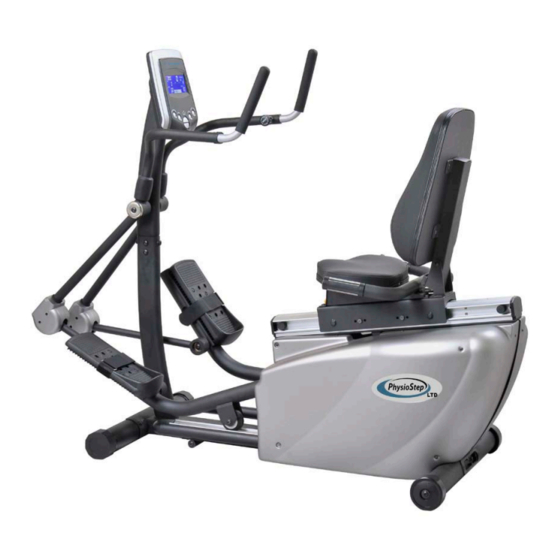
10. Keep clothes, jewelry or loose items away from moving parts. Please note: Maximum weight capacity for the PhysioStep is 330 lbs (150 kg) WARNING BEFORE BEGINNING ANY EXERCISE PROGRAM CONSULT YOUR PHYSICIAN. THIS IS ESPECIALLY IMPORTANT FOR INDIVIDUALS OVER THE AGE OF 35 OR PEOPLE WITH PRE-EXISTING HEALTH PROBLEMS. - Page 3 The unique design combines a stable and stress free recumbent sitting position, with the smooth and natural feel of an elliptical. The PhysioStep is easy to use, and will give you a cardiovascular workout while engaging your legs, arms and core.
-
Page 4: Exploded Drawing
EXPLODED DRAWING... -
Page 5: Parts List
PARTS LIST Description Description 1 Main Frame 30 DC Motor 2 Computer 31 Rear Leg Wheel 3 Magnetic Flywheel 32 Hexagonal Bolt M8*15L 4 Pedal Axle 33 Washer OD26*ID8.5*2T 5 Pulley 34 Aluminum Track Base 40*80*470L 6 Mushroom Screw-M6*15L 35 Aluminum Track Base Holder 7 Nylon Nut (M6) 36 Aluminum Track 348L 8 Belt-420-6J-PJ2505... - Page 6 Description Description 59 Seat 86 Place control 60 Seat Moving Set 87 Sensor Wire 61 Hand fixed block 88 Upper HR Sensor Wire 800mm L 62 Dipping Handle 89 Lower HR Sensor Wire 2460mm L 63 Pin ∮16*67L 90 Upper Computer Sensor Wire 64 Spring ∮2.0*∮18.5*36 91 Lower Computer Sensor Wire 65 Knob M16*P1.5*25L...
-
Page 7: Screw Set
SCREW SET: (100) 5m/m L Type Tool (83) 6m/m L Type Tool (99) 13*15 Tool NOTE Before you start to assemble this unit, please check to be sure you have the correct quantity of parts that are listed above. NOTE Some of the parts and screws needed for assembly are already in place on the unit. - Page 8 ASSEMBLY Step 1 Assembling the Seat Back Remove Bolts (No.32) from the seat back (No.75).Attach seat back (No.75) to seat back support (No.70) using bolts (No.32).Secure bolts tightly. Check tightness periodically. Step 2 Wire Connection Connect Upper Computer Sensor Wire (90) and Lower Computer Sensor Wire (91), Upper HR Sensor Wire (88) and Lower HR Sensor Wire (89).
- Page 9 ASSEMBLY Step 4 Connection Level Fixing 2 Insert the Rubber Cover (93) to the Moving Handle Set ( R ) (23) and fix the Moving Handle Set ( R ) (23) to the Moving Handle Set (28) using the bolt (32). Step 5 Stabilizing the Handle Bar Insert the Moving Handle Set (25) to the...
- Page 10 Step 7 Attaching the Joint Cover Attaching the Connecting Tube Cover (29) to the joint from the Moving Handle Set (28) and the Connecting Parts (22) using the screws (96). Step 8 Connecting the Power Put the end of the Adapter (No.46) in the input socket (No.45) on the back of the Main frame (No.1), then put the other end of the adapter (No.46) in the power outlet.
-
Page 11: Key Functions
PhysioStep LTD - Display/Monitor Manual This manual covers the following categories: Key Functions Display Operating Ranges Operating Instructions Additional Information Key Functions There are a total of 6 keys on the monitor; UP, DOWN, ENTER, START/STOP, PULSE AND MODE. A. UP (▲): Selects or increases the values of PROGRAMS, GENDER, TIME, HEIGHT, WEIGHT, WATT, CALORIES, TARGET HEART RATE, AGE, COUNT B. - Page 12 Display/Monitor A. START: Indicates the program selected has started. B. STOP: Indicates the program selected has stopped. C. PROGRAM: Indicates the programs selected from PROGRAM 1 to PROGRAM D. LEVEL: Indicates the level of resistance selected from LEVEL 1 to LEVEL 16. E.
-
Page 13: Operating Ranges
J. TARGET H.R./BMI/AGE Display: Indicates only one value of TARGET HEART RATE, BMI, or AGE displayed depending on the program. K. HEART RATE/BODY TYPE Display: Indicates only one value of HEART RATE or BODY TYPE displayed depending on the program. L. - Page 14 Operating Instructions A. Exercising With a Specific Goal: 1. TIME Control: Set your workout duration for a specific amount of time. (Except in Program 8) 2. COUNT Control: Set your workout duration for a specific “Count” of workout cycles. (Except in Program 8) 3.
- Page 15 E. Body Fat Program: Program 8 is designed to calculate users’ body fat ratio and to design a specific workout profile for users. Press “ENTER” key to select GENDER, HEIGHT, WEIGHT, and AGE. Then, press ▲ or ▼ key to adjust the values. Press the “START/STOP”...
- Page 16 H. Watt Independent Program: Program 17 is a Watt Independent Program. Press the “ENTER” set the TIME, COUNT, WATT, and AGE. Press the “START/STOP” key to begin exercise, and place your hands on the contact heart rate sensors. During exercise, the level of resistance is not adjustable.
- Page 17 C. Programs Selection: There are 17 workout programs and 1 Recovery program. Programs include: 1 Manual Program, 6 Preset Programs, 1 Body Fat Program, 4 Heart Rate Control Programs, 4 User Setting Programs, 1 WATTS Control Program, and 1 Pulse Recovery Program.
- Page 18 MAINTENANCE AND TECHNICAL DATA 1.1 Maintenance Tips • Keep the PhysioStep well maintained to ensure peak performance and safety. • Clean the display console and all exterior surface parts routinely. Use a soft cotton cloth and a soft cleaner for best results. Do not use Ammonia or acid based cleaners.
-
Page 19: Warranty Information
Trouble Shooting Guide for the PhysioStep LTD Malfunction Cause Solution The Display does not turn on 1. Console wire is disconnected 1. Detach and Re-connect when pedaling lightly. or connected improperly. console wires to make 2. Low Batteries in the Display sure they are connected 3.
Need help?
Do you have a question about the PhysioStep and is the answer not in the manual?
Questions and answers
I need to know the formula used to calculate the MET levels