
Related Manuals for HealthCare International PhysioStep HXT


Summary of Contents for HealthCare International PhysioStep HXT
- Page 1 ________________________Owner’s Manual V1.2 HealthCare International, Inc. PO Box 1509, Langley, WA 98260 www.HCIFitness.com P.360.321.7090...
- Page 2 - 1 -...
-
Page 3: Table Of Contents
Table of Contents SAFETY PRECAUTIONS ....................3 WARRANTY INFORMATION ..................4 ASSEMBLY ........................5 QUICK TIPS ........................8 BUTTON FUNCTIONS ....................9 QUICK START ........................ 9 SELECT A PROGRAM ....................9 MAINTENANCE ......................14 EXPLODED DIAGRAM ....................19 PARTS LIST........................20 - 2 -... -
Page 4: Safety Precautions
10. Keep clothes, jewelry or loose items away from moving parts. NOTE: Maximum weight capacity for the PhysioStep HXT is 330 lbs (150 kgs) WARNING BEFORE BEGINNING ANY EXERCISE PROGRAM CONSULT YOUR PHYSICIAN. THIS IS ESPECIALLY IMPORTANT FOR INDIVIDUALS OVER THE AGE OF 35 AND PEOPLE WITH PRE-EXISTING HEALTH PROBLEMS. -
Page 5: Warranty Information
Dear Valued Customer, Thank you for your recent purchase of the PhysioStep HXT from HCI Fitness. We believe that you have purchased one of the highest quality and affordable recumbent semi-ellipticals on the market today. Prior to using your new PhysioStep HXT please review the owner’s manual and product tips to maximize your workout experience. -
Page 6: Assembly
ASSEMBLY Step 1 Assembling Seat Back Remove Bolts (No.32) from the seat back (No.75). Attach seat back (No.75) to seat back support (No.70) using bolts (No.32). Secure bolts tightly. Check tightness periodically. Step 2 Wire Connection Align the connection so that the display is oriented towards the user. - Page 7 Step 3 Connect Lower Arm Assembly Arm Connections A. Remove the axle (52) from the moving handle (23). Be sure to keep the axle (52), bushing (53), washer (33), and bolt (32) for use in Step 3 - C B. Align the bushing (84) so that the axle (52) can be connected.
- Page 8 Step 6 Connect the Display Connect the Upper HR Sensor Wire (88) and the Upper Display Sensor Wire (90) to the same connection from the Display (2). Attaching the Display (2) to the Display Post (27) using the screws locking. Wire Pinch Point Step 8 Connect Power...
-
Page 9: Quick Tips
QUICK TIPS AC Adaptor: The PhysioStep HXT does need to be plugged into a standard electrical outlet. The AC adaptor connects at the rear base of the unit, at ground level, on the end of the unit that is beneath the seat. The display is powered by the adaptor and does not need batteries. -
Page 10: Button Functions
BUTTON FUNCTIONS START / STOP BUTTON 1.1. Pressing the START / STOP button begins a manual workout. 1.2. Pressing the START /STOP button during a workout will pause the workout. 1.3. Holding the START / STOP button will reset the display. ENTER BUTTON 2.1. - Page 11 SETUP WORKOUT PROGRAMS Before starting your workout make sure that your seat is comfortably adjusted. Operating Instructions A. Exercising With a Specific Goal: 1. TIME Control: Set your workout duration for a specific amount of time. (Except in Program 8) 2.
- Page 12 Users may adjust the resistance level by pressing ▲ or ▼ during the workout When you input your age, the computer may suggest a target heart rate. The suggested heart rate is 85% (220 – age). So, if the heart rate detected equals to or greater than the TARGET H.R., the value of HEART RATE will keep flashing.
- Page 13 rate sensors. You can change the resistance level during your workout at anytime by pressing ▲ or ▼ key. Please note, this will not store the change in the profile memory. The computer may suggest a target heart rate to exercise. The suggested heart rate is 85% (220 –...
- Page 14 Please note that only either the TIME or COUNT can be adjusted. Both adjustments cannot be made at the same time. For example, the value of COUNT is “0” while the value of TIME is adjusted to be any number except “00:00” C.
-
Page 15: Maintenance
E. Body Types: There are 9 body types divided according to the FAT% calculated. Type 1 is from 5% to 9%. Type 2 is from 10% to 14%. Type 3 is from 15% to 19%. Type 4 is from 20% to 24%. Type 5 is from 25% to 29%. - Page 16 TROUBLE SHOOTING GUIDE Symptom Possible Cause Solution The Adaptor is not plugged in? Check that the Adaptor is correctly connected to the Mains Power The LCD Screen does NOT Socket and is correctly connected to the Computer. Display anything The Computer is faulty? Replace the Computer by contacting your dealer.
- Page 17 Open the Computer Case, The connection between the remove the Circuit Board Circuit Board and the LCD Screws, gently remove the Screen Membrane is Circuit Board, reassemble the The LCD Screen Partially Misaligned. If this is the LCD Screen and/or the problem you might be able to Membrane taking care not to see that the LCD Screen is on a...
- Page 18 (1)Review the Assembly Instructions and check that all the Computer Plugs and Sockets are FIRMLY and correctly connected. (2)Review the Bike’s Magnetic Resistance System to ensure that it is set correctly and they be at it can freely be adjusted. A symptom of the previous problem is the Motor will struggle to adjust the resistance...
- Page 19 (1)Review the Bike’s Magnetic Resistance System to ensure that it is set correctly and they be at it can freely be adjusted. A symptom of the previous problem is the Motor will struggle to adjust the resistance and will start making an abnormal sound.
-
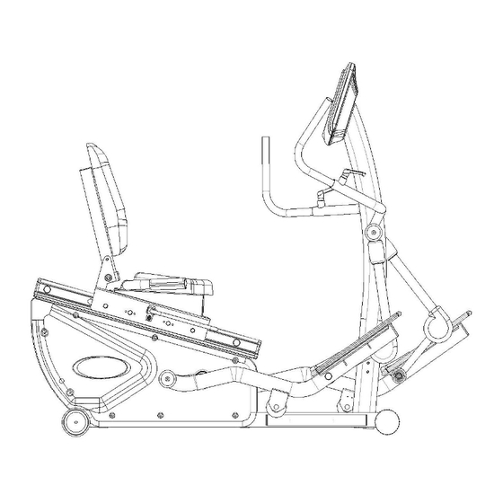
Page 20: Exploded Diagram
EXPLODED DRAWING - 19 -... -
Page 21: Parts List
PARTS LIST Description Description Main Frame 30 DC Motor Computer 31 Rear Leg Wheel Magnetic Flywheel 32 Hexagonal Bolt M8*15L Pedal Axle 33 Washer OD26*ID8.5*2T Pulley 34 Screw M4*10L Mushroom Screw-M6*15L 35 Screw M5*15L Nylon Nut (M6) 36 Stick of Number 37 Tube Cover∮38.1mm Belt Idler Set... - Page 22 Description Description 90 Upper Computer Sensor Wire 59 Seat 91 Computer Sensor Wire 60 Seat Moving Set 92 Power inlet 61 Hand fixed block 93 Nylon Nut M10 62 Dipping Handle 94 C-Ring-S35 63 Pin 95 C-Ring-S42 64 Spring 96 Mushroom Screw ST4.5*50L 65 Knob 66 Shaft for PU Wheel 97 Curved Washer M8...
- Page 23 - 22 -...
- Page 24 - 23 -...
Need help?
Do you have a question about the PhysioStep HXT and is the answer not in the manual?
Questions and answers
Hi, I need a replacement for my ac adapter. It’s for the HXT model. The adapter is an ahead class 2 transformer, model ADB-0600800. There is an on/off switch in the line. Can I purchase this from you or can you recommend a place for me to get one.