
Related Manuals for McQuay MicroTech 200 Series


Summary of Contents for McQuay MicroTech 200 Series
- Page 1 Operating Manual OM 200MICRO Group: Chiller Part Number: 585515Y Effective: April 2000 Supersedes: OM125 200-Series MicroTech Control Panel For Centrifugal Chillers © 1999 McQuay International...
-
Page 2: Table Of Contents
McQuay" and MicroTech are registered trademarks of McQuay International 1998 McQuay International "Illustrations and information cover McQuay International products at the time of publication and we reserve the right to make changes in design and construction at anytime without notice." OM 200MICRO... -
Page 3: Introduction
Introduction This manual provides installation, setup and troubleshooting information for the 200 Series MicroTech control panel for McQuay centrifugal chillers. Please refer to IOMM WSCWDC for information relating to the unit itself. All operational descriptions contained in this manual are based on MicroTech control software versions CFG3E04I (English) and CFG3S04I (metric). -
Page 4: General Description
4-line by 40-character keypad / display or by using an IBM compatible computer running McQuay Monitor software. In addition to providing all normal operating controls, the MicroTech controller monitors all safety devices on the unit and will take corrective action if the chiller is operating outside of it’s normal design conditions. - Page 5 **secondary evaporator and condenser operating states. Useful for system checkout. pumps. BAS communication capability via McQuay's Control of up to 4 stages of cooling tower Open Protocol strategy to over 10 major BAS fans plus modulating bypass valve.
-
Page 6: Component Description
Component Description Figure 2, Model 280 Microprocessor Control Board Microprocessor Control Board (MCB1) The Model 280 Microprocessor Control Board contains the electronic hardware and software required to monitor and control the unit. It receives input from the ADI Board and sends commands to the Output Board to maintain the unit's optimum operating mode for the current conditions. - Page 7 With the controller powered up and the green running LED illuminated, the backlite panel on the display module will be illuminated and the unit status menu will be visible. If the display text looks faded or appears as “blocks” the contrast control needs to be adjusted. Watch the display and adjusting the contrast control with a small flat-blade screwdriver until the best setting is determined.
- Page 8 Table 1, Digital Outputs Description LED Off LED On Alarm LED and Contact Programmable Programmable Unload Solenoid and Front Panel LED Unload Load Solenoid and Front Panel LED Load Motor Control Relay Motor Control Relay Latch Unlatched Latched Oil Pump Oil Sump Heater Oil Cooler close Oil Cooler Open...
- Page 9 of 4-20 mA. Temperature and pressure readings have a resolution of 0.1F and 0.1 psi respectively. Flow readings and remote reset signals are resolved to 1%. OM 200MICRO...
- Page 10 Table 2, Controller Input Signals ADI Sensor No. Description Range Leaving Evaporator Water Temperature -40 - 263 F (-40-128.4°C) Entering Evaporator Water Temperature -40 - 263 F (-40-128.4°C) Compressor Suction Temperature -40 - 263 F (-40-128.4°C) External Chilled Water Reset (by others) 4-20mA = 0-100% External motor Current Reset (by others) 4-20mA = 0-100%...
- Page 11 Analog Output Board (AOX) The AOX board converts control instructions from the Microprocessor Control Board’s expansion bus into an analog control signal suitable for driving a cooling tower bypass valve. Each AOX board is factory set via jumper to provide an output signal range of 0 - 10 VDC. An additional output on the AOX board provides an analog signal that is proportional to compressor motor current.
- Page 12 Signal Converter Board The AC current signal generated by the starter is converted by the signal converter board into a 0-5 VDC signal that is directly proportional to the chiller amp draw. The amp draw signal is sent to the ADI board for conditioning and then to the M280 controller.
-
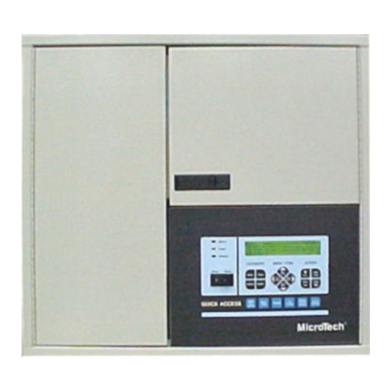
Page 13: Keypad/Display Operation
Keypad/Display Operation The Keypad/Display is the primary operator interface to the unit. All operating conditions, system alarms and setpoints can be monitored from this display and all adjustable setpoints can be modified from this keyboard if the operator has entered a valid operator password. General Description The MicroTech keypad consists of eighteen pressure sensitive membrane switches used to step through, access, and manipulate the information in the MicroTech controller. - Page 14 Category Group The keys in this group provide quick access to strategic menus throughout the menu tree-structure. This reduces the need to step through all the menus, one by one, in order to reach the desired information. Figure 12, Category Group Status Key Menus and menu items in this category provide information on the MicroTech operating conditions and the chiller operating conditions.
- Page 15 Menu - Item Group Figure 13, Menu - Item Group Prev. Item Next Prev. Menu Menu Next Item The keys in this group are used to scroll through the various menus and items presented on the controller’s display. A menu contains a specific group of items. Note: When Menu #1 is currently in the display (the first menu in the menu tree-structure), pressing "PREV."...
- Page 16 Increment When changing the value of a menu item entry, pressing ''INCR. +" shifts the selected menu item to the next higher value or next available selection. Decrement When changing the value of a menu item entry, pressing "DECR.-" shifts the selected menu item to the next lower value or previous available selection.
-
Page 17: Menu Structure
English Customary Units: Temperature = ºF (Fahrenheit) Pressure = (Pound per sq. inch) Psig Psid Metric Units: Temperature = ºC (Centigrade) Pressure = (Kilo Pascals) kPag kPda Menu Structure Displaying Setpoints To view set points or operating conditions press the "PREV MENU" or "NEXT MENU" key until menu of interest appears. -
Page 18: Microtech Status Menus
MicroTech Status Menus Press the "STATUS" key under the Category Group and the information in Menu 1 (Unit Status) will be displayed. Information displayed in menus 1-10 indicates current operating conditions and cannot be reset from the display keypad. Refer to the Metric Menu section for displays in metric values. This menu has one screen with three lines of information. - Page 19 temperature and line 2, field 2 indicates the leaving condenser water temperature. Line 3, field 1 indicates the evaporator delta temperature. This is the difference between the entering and leaving water temperature and indicates the 'load' on the chiller and the performance of the chiller. Line 3, field 2 indicates the condenser delta temperature.
- Page 20 approach temperature. This temperature is calculated by subtracting the evaporator refrigerant temperature from the evaporator leaving water temperature. Press the "NEXT ITEM" key and screen 3 will display additional information. Line 1, field 1 indicates the compressor lift pressure. This value is calculated by subtracting the evaporator pressure from the condenser pressure.
- Page 21 Press the "NEXT MENU" key and Menu 6 (Pump Status) will be displayed. Menu six has one screen. Line 1, field 1 displays the evaporator pump running status. Line 1, field 2 displays the condenser pump running status. Line 2, field 1 indicates which evaporator pump is operating as the lead pump. Line 2, field 2 indicates which condenser pump is operating as the lead pump.
- Page 22 Menu 8, Operating Hours Item Screen Line Display Field Range Extended Name Comp Hours=xxxxx Compressor Operating Hours Starts=xxxx Compressor Starts Time of Last Chiller Start Last Start=xx:xx mm/dd/yy Date of Last Chiller Start Time of Last chiller Stop Last Stop=xx:xx mm/dd/yy Date of Last Chiller Stop Evap Pmp #1=xxxx Evap Pump #1 Run Hours...
- Page 23 Menu 10, Auto Logging Item Screen Line Display Field Range Extended Name Wk Ending Date of Current Log Peak=xxx% Recorded Peak % RLA Evap=xx.xxpsi Recorded Evaporator Pressure mm-dd xx:xx Date and Time of Log Entry Cond=xxx.xpsi Recorded Condenser Pressure Ent Evap=xx.x°F Recorded Ent Evap Water Temp Ent Cond=xx.x°F Recorded Ent Cond Water Temp...
-
Page 24: Control Menu Description
Control Menu Description Press the "CONTROL" key under the 'Category Group' and Menu 11 (Control Mode) will be displayed. Menus 11-26 are the control menus. All control set points and value selections are entered into the MicroTech from these menus. The default set point is indicated under the display column and the range of set points or values are indicated in the range column. - Page 25 Menu 12, Leaving Evap Set Points Item Screen Line Display Field Range Extended Name Local Lvg Set Point Source Spt Source=Local Network Active Spt=xx.x°F Current Active Set Point Local Spt=44.0°F 40-80 User Adjustable Chw Set Point Startup DT=3.0°F 1-10 Startup Delta Temp Network Spt=xx.x°F Chw Spt Supplied by Network Shutdn DT=3.0°F...
- Page 26 4-20mA—This is an optional input to the MicroTech. This input is usually from a building automation system. As the input changes from 4 to 20 mA, the leaving chilled water temperature is increased from local spt (in a linear manner) until the max lvg spt is reached. When the spt source is set to network, the 4-20 mA input is supplied to the master MicroTech control.
- Page 27 Demand Limit—Allows the MicroTech to control chiller motor amperage based on a remote 4-20 mA signal supplied by a building automation system input. The 4-20 mA signal limits the capacity of the chiller and saves electrical demand charges. Active Spt= This is a status value and cannot be changed. Active spt indicates the set point that is controlling the chiller.
- Page 28 Menu 15, Schedule Item Screen Line Display Field Range Extended Name Override=00.0Hr 00.00-63.75 Manual Schedule Override Network Sched= 1-32 Network Time Schedule Sun 00:00-23:59 00:00-23:59 Sunday Run Schedule Tue 00:00-23:59 00:00-23:59 Tuesday Run Schedule Mon 00:00-23:59 00:00-23:59 Monday Run Schedule Wed 00:00-23:59 00:00-23:59 Wednesday Run Schedule...
- Page 29 Table 16 Continued Item Screen Line Display Field Range Extended Name Jan-Dec Holiday Month #7=N/A-00 00 Day(s) 00-31 Holiday Date 00-31 Duration Days Jan-Dec Holiday Month #10=N/A-00 00 Day(s) 00-31 Holiday Date 00-31 Duration Days Jan-Dec Holiday Month #8=N/A-00 00 Day(s) 00-31 Holiday Date 00-31...
- Page 30 Menu 18, Pump Set Points Item Screen Line Display Field Range Extended Name Pmp 1 Only Pmp 2 Only Evap=Pmp 1 Only Auto Lead Evap Pump Selection Mode #1 Primary #2 Primary Pmp 1 Only Pmp 2 Only Cond=Pmp 1 Only Auto Lead Cond Pump Selection Mode #1 Primary...
- Page 31 stage down time. The number of stages also will be decreased when the maximum number of stages is less than the current stage. The sequence described above allows stages to be turned on based on temperature only or on a combination of temperature and time.
- Page 32 The number of cooling tower stages is decreased only when the valve position drops below the minimum position set point and the temperature and time requirements described above for fan staging down are met. The valve then modulates open as the temperature starts to rise after the fan stage is turned off.
- Page 33 Min Start Pos= This value will control the minimum position of the valve during pre-start at a pre- selected (Min Pos At=) outside air temperature. Max Start Pos= This value will control the maximum position of the valve during pre-start at a pre-selected (Max Pos At=) outside air temperature.
- Page 34 Menu 23, Lead Lag Setup Item Screen Line Display Field Range Extended Name Slave Address=01.00 00-09 Slave Unit Network Address NoUnload Start-Up=NotUnld Unload Lead During Lag Start Unload Auto LL Mode=auto Slave Lead Lead Lag Control Mode Master Lead Enable Lag=95% 0-100% Lag Start Threshold Scheduled Lead Unit Switch...
- Page 35 Menu 24, Service Item Screen Line Display Field Range Extended Name Manual Load=Off Off-on Enable Manual Loading Hot Gas Bypass=30% 20-70% Hot Gas Bypass Enable Setpoint Setpoint=40% 0-100% Manual Load Setpoint Post Lube=15 10Sec-5Min Oil Pump Delay Off Time Normal Timers=Normal Setup Timers for Service Fast...
- Page 36 Basic Chiller Setup Press the "NEXT MENU" key and menu 26 (Unit Setup) will be displayed. Menu 26 has three screens. This menu is password protected and requires the operator password. Changing the values in this menu can cause network communications failure. There are several menus that require resetting the default values for proper unit operation.
- Page 37 Port A Baud= This value defines the communication baud rate for port A. This is critical if there is a network. (Port A baud rate must be set to 9600 on the master unit.) Low Temperature= This value selects the operational mode of the unit. If 'ice' is selected, the MicroTech default values have to be reset to match the system requirements for an "Ice"...
-
Page 38: Alarm Menus Description
Alarm Menus Description Press the "ALARM" key under the 'Category Group' and menu 27 (Alarms) will be displayed. Menus 27-35 are the alarm menus. Menu 27 has four screens. This menu is a display and does not require a password. The values displayed indicate the current alarm and the conditions at the time the alarm reported. - Page 39 Evap Flow=xxxxgpm Evaporator Water Flow at Alarm Cond Flow=xxxxgpm Condenser Water Flow at Alarm Follow the above sequence to view the alarm menu 29-35 (Alarm Buffers #2-#8). Press the "NEXT MENU" key and menu 36 (Alarm Output) will be displayed. Menu 36 has one screen.
- Page 40 Menu 37, Message Board Item Screen Line Display Field Range Extended Name A Message can be Posted via a No Message Connected Computer OM 200MICRO...
-
Page 41: Master/Slave Setup
Master/Slave Setup Chiller setup for dual unit (WDC) or two single (WSC) units with master/slave and or lead/lag control. There are several menus that require modification to accomplish this setup. The first menu that has to be modified is menu 26. One MicroTech controller has to be designated as the Master unit. The other unit will be the Slave unit. - Page 42 Menu 23, Lead Lag Setup Item Screen Line Display Field Range Extended Name Slave Address=01.00 00-09 Slave Unit Network Address NoUnload Start-Up=NotUnld Unload Lead During Lag Start Unload Auto LL Mode=auto Slave Lead Lead Lag Control Mode Master Lead Enable Lag=95% 0-100% Lag Start Threshold Scheduled Lead Unit Switch...
-
Page 43: Alarms
Alarms Any condition that requires corrective action by the controller that overrides normal chiller operation or any condition that initiates an emergency chiller shutdown can be considered to be an alarm. Alarms are arranged in increasing priority with higher priority alarms replacing any lower priority alarms that may exist. - Page 44 Problems, continued PROBLEM CONDITION DISPLAY ACTION CLEAR Evaporator Refrigerant Evaporator Refrigerant Temperature > Evaporator Freeze Temperature < Start the Evaporator Evap Pres Lo-Freeze Evaporator Freeze Protect Evaporator Freeze pump Protect Set Point + Protect Set Point (34°F) Differential (2°F) UnitStatus > EvapPmpOn_Recirc and UnitStatus <...
- Page 45 Faults The chiller will be shut down by the MicroTech control panel in response to any of the following fault conditions. These faults must be cleared manually to restart the unit. FAULT CONDITION DISPLAY Low Evaporator Pressure Evaporator Pressure is less than low limit (26 psig) Lo Evap Pressure-SD Oil Pump output has been energized for more then 30 seconds and Oil Feed Pressure is less than the...
- Page 46 Post Office Box 2510, Staunton, Virginia 24402-2510 (800) 432-1342 www.mcquay.com...
Need help?
Do you have a question about the MicroTech 200 Series and is the answer not in the manual?
Questions and answers