
Related Manuals for McQuay ALR 032E


Summary of Contents for McQuay ALR 032E
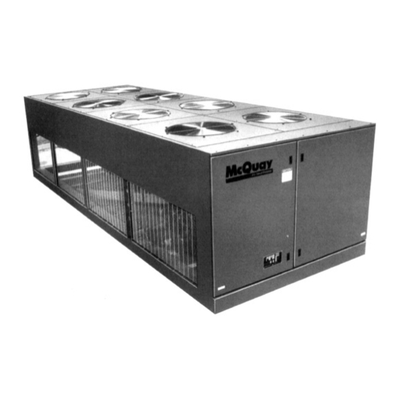
- Page 1 Installation Manual IM 676 Group: Chiller Part Number: 594920Y Date: July 1996 Supersedes: None SeasonPak Packaged Air-Cooled Water Chiller Models ALR 032E Through 185E © 1996 McQuay International...
-
Page 2: Table Of Contents
Table of Contents Introduction ......................3 General Description......................... 3 Inspection............................3 Installation ............................3 Handling ............................3 Location ............................4 Service Access ..........................5 Vibration Isolators ........................... 6 Water Piping............................ 7 Flow Switch............................. 8 Water Connections........................... 8 Refrigerant Charge .......................... 9 Glycol Solutions .......................... -
Page 3: Introduction
Check all items carefully against the bill of lading. Inspect all units for damage upon arrival. Report shipping damage and file a claim with the carrier. Check the unit name plate before unloading, making certain it agrees with the power supply available. McQuay is not responsible for physical damage after unit leaves the factory. -
Page 4: Location
Figure 1, Suggested pushing arrangement Blocking required across full width Figure 2, Suggested lifting arrangement Spreader bars recommended (Use Caution) NOTE: Number of fans can vary from this diagram. Lifting method remains the same. Must use these rigging holes. (Be aware of control box location) Location Unit Placement... -
Page 5: Service Access
Clearances The flow of air to and from the condenser coil must not be limited. Restricting air flow or allowing air recirculation will result in a decrease in unit performance and efficiency. There must be no obstruction above the unit that would deflect discharge air downward where it could be recirculated back to the inlet of the condenser coil. -
Page 6: Vibration Isolators
CP-2-32 2002 CP-2-32 1849 NOTE: Two of each isolator type is required for a total of six per unit. Table 2, Spring flex isolator part numbers Max. Load TYPE COLOR McQuay Each Part No. CP1-25 477927A-25 CP1-26 Purple 477927A-26 CP1-27... -
Page 7: Water Piping
Water Piping Local authorities can supply the installer with the proper building and safety codes required for safe and proper installation. Install piping with minimum bends and changes in elevation to minimize pressure drop. Consider the following when installing water piping: 1. -
Page 8: Flow Switch
Mount a water flow switch in either the entering or leaving water line to shut down the unit when water flow is interrupted. A flow switch is available from McQuay (part number 00175033-00). It is a “paddle” type switch and adaptable to any pipe size from 3” (76mm) to 8” (203mm) nominal. Certain minimum flow rates are required to close the switch and are listed in Table 3. -
Page 9: Refrigerant Charge
Note: On units sizes 160E through 185E there is a diagonal bracket off of a vertical support which will interfere with the water connection if brought in from the side. This brace can be removed, but only after the unit is in place. Refrigerant Charge All units are designed for use with HCFC-22 and other refrigerants. - Page 10 CAUTION Do not use an automotive grade antifreeze. Industrial grade glycols must be used. Automotive antifreeze contains inhibitors which will cause plating on the copper tubes within the chiller evaporator. The type and handling of glycol used must be consistent with local codes.
-
Page 11: Evaporator Water Flow And Pressure Drop
Evaporator Water Flow and Pressure Drop Evaporator flow rate must fall between the minimum and maximum values shown in the evaporator pressure drop curve. Flow rates below the minimum values will result in laminar flow which will reduce efficiency, cause erratic operation of the expansion valve and could cause low temperature cutouts. -
Page 12: Physical Data
Physical Data Table 7 , Physical data ALR032E Through 050E PHYSICAL DATA ALR MODEL NUMBER 032E 035E 040E 045E 050E BASIC DATA Ckt.1 Ckt.2 Ckt.1 Ckt.2 Ckt.1 Ckt.2 Ckt.1 Ckt.2 Ckt.1 Ckt.2 Unit Capacity @ ARI Conditions (1), 32.5 (114.3) 34.6 (121.7) 40.4 (142.0) 45.9 (161.4) - Page 13 Table 8, Physical data ALR055E Through 075E PHYSICAL DATA ALR MODEL NUMBER 055E 060E 065E 070E 075E BASIC DATA Ckt.1 Ckt.2 Ckt.1 Ckt.2 Ckt.1 Ckt.2 Ckt.1 Ckt.2 Ckt.1 Ckt.2 Unit Capacity @ ARI Conditions (1), Tons (kW) 54.6 (192.0) 59.6 (209.6) 64.0 (225.0) 69.0 (242.6) 72.2 (253.9)
- Page 14 Table 9, Physical data ALR080E Through 100E PHYSICAL DATA ALR MODEL NUMBER 080E 085E 090E 100E BASIC DATA Ckt.1 Ckt.2 Ckt.1 Ckt.2 Ckt.1 Ckt.2 Ckt.1 Ckt.2 Unit Capacity @ ARI Conditions (1), Tons (kW) 81.3 (285.9) 85.3 (300.0) 92.7 (326.0) 99.2 (348.8) Number Of Refrigerant Circuits Unit Operating Charge, R-22, Lb.
- Page 15 Table 10, Physical data ALR100E Through 135E PHYSICAL DATA ALR MODEL NUMBER 110E 120E 130E 135E BASIC DATA Ckt.1 Ckt.2 Ckt.1 Ckt.2 Ckt.1 Ckt.2 Ckt.1 Ckt.2 Unit Capacity @ ARI Conditions (1), Tons (kW) 107.8 (379.0) 120.7 (424.4) 130.6 (459.2) 135.5 (476.4) Number Of Refrigerant Circuits Unit Operating Charge, R-22, Lb.
- Page 16 Table 11, Physical data ALR140E Through 160E PHYSICAL DATA ALR MODEL NUMBER 140E 145E 150E 160E BASIC DATA Ckt.1 Ckt.2 Ckt.1 Ckt.2 Ckt.1 Ckt.2 Ckt.1 Ckt.2 Unit Capacity @ ARI Conditions (1), Tons (kW) 139.7 (491.2) 144.7 (508.8) 149.9 (527.0) 157.8 (554.8) Number Of Refrigerant Circuits Unit Operating Charge, R-22, Lbs...
- Page 17 Table 12, Physical data ALR170E Through 185E PHYSICAL DATA ALR MODEL NUMBER 170E 180E 185E BASIC DATA Ckt.1 Ckt.2 Ckt.1 Ckt.2 Ckt.1 Ckt.2 Unit Capacity @ ARI Conditions (1), Tons (kW) 167.2 (587.9) 177.3 (623.4) 185.8 (653.3) Number Of Refrigerant Circuits Unit Operating Charge, R-22, Lb.
-
Page 18: Electrical Data
Electrical Data Field Wiring CAUTION Internal power wiring to the compressors for single and multiple point option are different. Field wiring must be installed according to unit wiring diagram. Wiring must comply with all applicable codes and ordinances. Warranty is void if wiring is not in accordance with specifications. - Page 19 Table 13, 032E - 070E Electrical Data Single Point Minimum POWER SUPPLY FIELD FUSE SIZE Circuit Field Wire Unit Volts Ampacity Wire Nominal Recommended Maximum Size (MCA) Quantity Gauge Quantity Size 1.50 (38) 1.50 (38) 032E 1.00 (25) 1.00 (25) 1.50 (38) 1.50 (38) 035E...
- Page 20 Table 14, 080E - 135E Electrical Data Single Point Minimum POWER SUPPLY FIELD FUSE SIZE Circuit Field Wire Unit Volts Ampacity Wire Nominal Recommended Maximum Size (MCA) Quantity Gauge Quantity Size 3.00 (76) 3.00 (76) 080E 2.00 (51) 1.50 (51) 3.00 (76) 3.00 (76) 085E...
- Page 21 Table 15, 140E - 185E Electrical Data Single Point Minimum POWER SUPPLY FIELD FUSE SIZE Circuit Field Wire Unit Volts Ampacity Wire Nominal Recommended Maximum Size (MCA) Quantity Gauge Quantity Size 3.00 (76) 3.00 (76) 140E 2.50 (64) 2.50 (64) 3.00 (76) 3.00 (76) 145E...
- Page 22 Table 16, 032E - 075E Electrical Data Multiple Point Electrical Circuit #1 - Fans and Transformer Electrical Circuit #2 - Compressor Circuit #1 Electrical Circuit #3 - Compressor Circuit #2 Min. Power Supply Field Fusing Min. Power Supply Field Min. Power Supply Field Fusing Fusing...
- Page 23 Table 17, 032E - 075E Electrical Data Multiple Point (continued) Electrical Circuit #1 - Fans and Transformer Electrical Circuit #2 - Compressor Circuit #1 Electrical Circuit #3 - Compressor Circuit #2 Min. Power Supply Field Min. Power Supply Field Min. Power Supply Field Fusing...
- Page 24 Table 19, 080E - 135E Electrical Data Multiple Point (continued) Electrical Circuit #1 - Fans and Transformer Electrical Circuit #2 - Compressor Circuit #1 Electrical Circuit #3 - Compressor Circuit #2 Min. Power Supply Field Min. Power Supply Field Min. Power Supply Field Fusing...
- Page 25 Table 26, 140E - 185E Electrical Data Multiple Point (continued) Electrical Circuit #1 - Fans and Transformer Electrical Circuit #2 - Compressor Circuit #1 Electrical Circuit #3 - Compressor Circuit #2 Min. Power Supply Field Fusing Min. Power Supply Field Fusing Min.
- Page 26 Table 21, 032E - 075E Compressor And Condenser Fan Motor Amp Draw Rated Load Amps Locked Rotor Amps Compressors No. Of Compressors Unit Volts Motors Motors Across-The-Line Reduced Inrush Size (Each) Motors (Each) No. 1 No. 2 No. 3 No. 4 No.
- Page 27 Table 22, 080E -135E Compressor And Condenser Fan Motor Amp Draw Rated Load Amps Locked Rotor Amps Compressors No. Of Compressors Unit Volts Motors Motors Across-The-Line Reduced Inrush Size (Each) Motors (Each) No. 1 No. 2 No. 3 No. 4 No.
- Page 28 Table 23, 140E - 185E Compressor And Condenser Fan Motor Amp Draw Rated Load Amps Locked Rotor Amps Compressors No. Of Compressors Unit Volts Motors Motors Across-The-Line Reduced Inrush Size (Each) Motors (Each) No. 1 No. 2 No. 3 No. 4 No.
- Page 29 Table 24, 032E -075E Field Wiring Data, Single Point Power Wiring to Wiring to Standard Power Block Optional Disconnect Switch Unit Volts Terminal Connector Wire Range Terminal Connector Wire Range Size Amps (Copper Wire Only) Amps (Copper Wire Only) (1 qty.) #4 - 400 MCM (1 qty.) #3 - 300 MCM (1 qty.) #4 - 400 MCM (1 qty.) #3 - 300 MCM...
- Page 30 Table 25, 080E - 135E Field Wiring Data ,Single Point Power Wiring to Wiring to Standard Power Block Optional Disconnect Switch Unit Volts Terminal Connector Wire Range Terminal Connector Wire Range Size Amps (Copper Wire Only) Amps (Copper Wire Only) (2 qty.) 1/0 - 600 MCM (1 qty.) 250 - 500 MCM (2 qty.) 1/0 - 600 MCM...
- Page 31 Table 26, 140E - 185E Field Wiring Data, Single Point Power Wiring to Wiring to Standard Power Block Optional Disconnect Switch Unit Volts Terminal Connector Wire Range Terminal Connector Wire Range Size Amps (Copper Wire Only) Amps (Copper Wire Only) (2 qty.) 1/0 - 600 MCM (2 qty.) 1/0 - 600 MCM 140E...
- Page 32 Table 27, 032E - 075E Field Wiring Data, Multiple Point Power Wiring to Standard Power Block Unit Volts Terminal Amps Connector Wire Range (Copper Wire Only) Size Circuit 1 Circuit 2 Circuit 3 Circuit 1 Circuit 2 Circuit 3 (1 qty.) #12 - 2/0 (1 qty.) #12 - 2/0 (1 qty.) #12 - 2/0 (1 qty.) #12 - 2/0...
- Page 33 Table 28, 080E - 185E Field Wiring Data, Multiple Point Power Wiring to Standard Power Block Unit Volts Terminal Amps Connector Wire Range (Copper Wire Only) Size Circuit 1 Circuit 2 Circuit 3 Circuit 1 Circuit 2 Circuit 3 (1 qty.) #12 - 2/0 (1 qty.) #4 - 400 MCM (1 qty.) #4 - 400 MCM (1 qty.) #12 - 2/0...
- Page 34 Notes for “Electrical Data Single Point” and “Electrical Data Multiple Point” Power: 1. Unit wire size ampacity (MCA) is equal to 125% of the largest compressor-motor RLA plus 100% of RLA of all other loads in the circuit including the control transformer. 2.
- Page 35 Figure 7,ALR 032E through 185E, typical field wiring diagram IM 676...
-
Page 36: Dimensional Data
Dimensional Data Figure 8, 032E through 100E Dimensions EVAPORATOR WATER CONNECTIONS CENTER OF GRAVITY ISOLATOR LOCATION NUMBER UNIT "A" CONN. SIZE LENGTH SIZE (1) FANS 032E 123 (3124) 4 (102) 96.3 (2446) 11.0 (279) 22.7 (477) 14.9 (378) 55.0 (1397) 41.7 (1059) 13 (330) 43 (1092) 109 (2769) - Page 37 Figure 9, 110E through 185E Dimensions EVAPORATOR CENTER OF GRAVITY ISOLATOR LOCATION NUMBER UNIT "A" CONN. WATER CONNECTIONS SIZE LENGTH SIZE (1) FANS 110E 229 (5817) 6 (152.4) 117.6 13.8 (351) 19.5 (495) 106.5 41.7 (1059) 13 (330) 58 (1473) 215 (5461) (2987) (2705)
-
Page 38: Unit Layout And Principles Of Operation
The low voltage components are located on the left side with the live terminals behind the deadfront panel. This protects service personnel from live terminals when accessing the adjustable and resettable controls. Control center layouts ALR 032E through 75E Figure 11, Left side, 115V control section Figure 12, Right side, high voltage power... - Page 39 Control center layouts ALR 080E through 185E Figure 13, Left side, 115V control section Figure 14, Right side, high voltage power section Note: PB1, PB2, PB3 are used with multiple point power wiring Figure 15,Recommended field installed unit disconnect location Stationary Panel Hinged Doors on Control Center...
-
Page 40: Start-Up And Shutdown
Start-up and Shutdown Pre Start-up 1. Open all electric disconnects and check all electric connections for tightness. Check all compressor valve connections for tightness. 2. Inspect all water piping for flow direction and correct connections at the evaporator. 3. Verify thermostat water temperature sensor is installed in the leaving water line (supply to building). -
Page 41: Sequence Of Operation
Sequence of Operation The following sequence of operation is typical for ALR SeasonPak air-cooled water chiller, Models ALR 032E through ALR 185E (items in italics apply only to Models ALR 080E through 185E). The sequence varies depending upon options. Start - up... - Page 42 Pumpdown As the leaving water control is satisfied, it will unload the compressor(s) and then de-energize the liquid line solenoid valve(s) SV1 and SV2, causing the valve(s) to close. When the compressor has pumped most of the refrigerant out of the evaporator and into the condenser, the low pressure control(s) LP1 and LP2 will open.
- Page 44 13600 Industrial Park Boulevard, P.O. Box 1551, Minneapolis, MN 55440 USA (612) 553-5330...
Need help?
Do you have a question about the ALR 032E and is the answer not in the manual?
Questions and answers