Table of Contents

Related Manuals for McQuay PM AGZ-2


Summary of Contents for McQuay PM AGZ-2
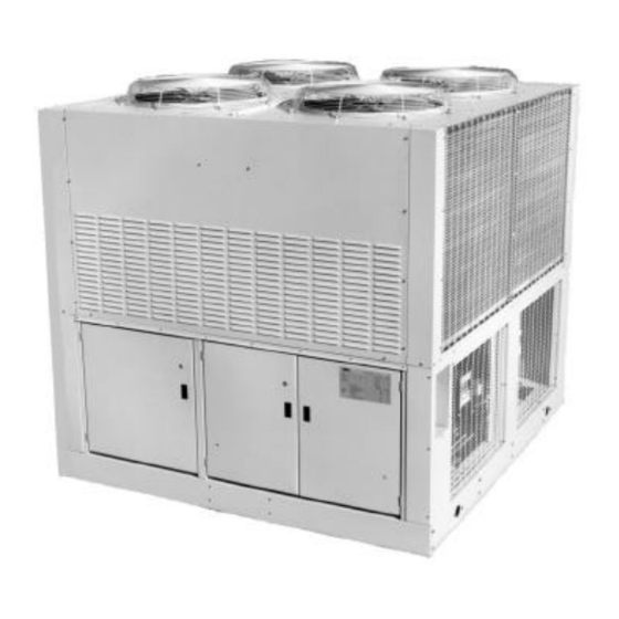
- Page 1 Product Manual PM AGZ-2 Group: Chiller Effective: May 1999 Supersedes: PM AGZ-1 Air-Cooled Scroll Compressor Chiller AGZ 030AS - 065AS, Packaged Chiller AGZ 030AM – 050AM, Chiller with Remote Evaporator 60 Hertz, R-22 © 1997 McQuay International...
-
Page 2: Table Of Contents
"McQuay" is a registered trademark of McQuay International © 1997 McQuay International "Illustrations cover the general appearance of McQuay International products at the time of publication and we reserve the right to make changes in design and construction at anytime without notice" AGZ 030A through 065A... -
Page 3: Introduction
Introduction McQuay offers air-cooled chillers from 10 through 425 tons (35 – 1500 kW). This manual covers two varieties of the scroll compressor, air-cooled Global Chiller Line: AGZ 030AS through AGZ 065AS, Packaged Air-Cooled Chillers AGZ 030AM through AGZ 050AM, Air-Cooled with Remote Evaporator. -
Page 4: Design Advantages
Condenser coils have internally enhanced seamless copper tubes arranged in a staggered row pattern. The coils are mechanically expanded into McQuay lanced and rippled aluminum fins with full fin collars. An integral subcooler circuit provides subcooling to effectively eliminate the possibility of liquid flashing. - Page 5 Evaporator The evaporator is direct expansion, shell-and-tube type with water flowing in the baffled shell side and refrigerant flowing through the tubes. Two independent refrigerant circuits within the evaporator serve the units dual refrigerant circuits. The evaporator has a carbon steel shell and seamless high efficiency copper tubes roller expanded into a carbon steel tube sheet.
- Page 6 Electrical Control Center Operating and safety controls and motor starting components are separately housed in a centrally located, weatherproof control panel with hinged and key locked doors. In addition to one of the three types of control described in the next sections, the following components are housed in the panel: •...
- Page 7 Global UNT with Optional Zone Terminal Provides for onboard (or remotely wired) monitoring or adjusting of certain functions. • Monitoring • Monitor up to three setting or sensed values • Monitor 18 different on/off inputs • Monitor alarm status via a flashing alarm light and flashing symbol •...
- Page 8 Figure 3, Optional Zone Terminal Configuration Display Item List Warning Signal Display Indicator Dot On/Off Status McQuay AGZ/AGR Global Chiller INSERT 10 Occupied Display Area Lvg Water Temp Flow Failure Evap Pres #1 Display OA Lockout Evap Pres #2 Cir#2Lead=On...
- Page 9 MicroTech Control (optional) Exclusive microprocessor control common throughout McQuay equipment. The interface is a 12 key keypad and 2-line, 16 character backlit liquid crystal display in plain English. The MicroTech continuously performs self-diagnostic checks on all system temperatures, pressures, and safeties, and will automatically shut down a circuit or the entire unit at fault conditions, and close a set of alarm contacts.
-
Page 10: Selection Procedure
Ratings are based on a 0.0001 fouling factor in the evaporator at sea level operation. For other fouling factors, different delta-Ts, or altitude correction factors see Table 3. For applications outside the catalog ratings contact your local McQuay sales representative. Selection example... - Page 11 Table 2 for propylene glycol adjustment factors. Ratings are based on a 0.0176 fouling factor in the evaporator at sea level operation. For other fouling factors, derates for different Delta-Ts, or altitude correction factors see Table 3. For applications outside the catalog ratings contact your local McQuay sales representative.
-
Page 12: Remote Evaporator, Model Am
Ratings are based on a 0.0001 (0.0176) fouling factor in the evaporator at sea level operation. For other fouling factors, derates for different delta-Ts, or altitude, see Table 3. For applications outside the catalog ratings contact your local McQuay sales representative. The length and configuration of the field installed interconnecting refrigerant piping will affect the system capacity. - Page 13 Add 3% to the required capacity for approximate derate: 42 x 1.03 = 43.3 tons. From Performance Table 9 an AGZ-045AM at the given conditions will produce 44.3 tons with a compressor kW input of 46.9 and a unit EER of 10.0. Determine derate factors: Altitude correction from Table 3;...
-
Page 14: Application Adjustment Factors
Application Adjustment Factors Ethylene and Propylene Glycol Factors AGZ units can operate with a leaving chilled fluid temperature range of 20°F (-6°C) to 50°F (10°C). A glycol solution is required when leaving chilled fluid temperature is below 40°F (4.6°C). The use of glycol will reduce the performance of the unit depending on concentration. - Page 15 Table 3, Capacity and Power Derates Chilled Water Fouling Factor Delta-T 0.0001 (0.0176) 0.00025 (0.044) 0.00075 (0.132) 0.00175 (0.308) ALTITUDE °F °C Cap. Power Cap. Power Cap. Power Cap. Power 0.992 0.995 0.985 0.993 0.962 0.986 0.919 0.972 0.995 0.997 0.988 0.995 0.965...
- Page 16 Table 6, Recommended Horizontal or Downflow Suction Line Size Connection Recommended Suction Line Sizes Unit Model Size Up to Up to Up to Up to Up to At Unit 50 Equiv. Ft 75 Equiv. Ft 100 Equiv. Ft 125 Equiv. Ft 150 Equiv.
-
Page 17: Performance Data
Ratings are based on circuit #1 in lead position and circuit #2 in lag position. Interpolation is allowed; extrapolation is not permitted. Consult McQuay for performance outside the cataloged ratings. KWi input is for compressors only. EER is for the entire unit, including compressors, fan motors and control power. - Page 18 Ratings are based on circuit #1 in lead position and circuit #2 in lag position. Interpolation is allowed; extrapolation is not permitted. Consult McQuay for performance outside the cataloged ratings. KWi input is for compressors only. COP is for the entire unit, including compressors, fan motors and control power.
-
Page 19: Part Load Data
Part Load Data Table 11, AGZ 030AS through 065AS 60 Hz Unit Size % Load Capacity Power Tons Unit kW IPLV 100.00 30.6 36.4 10.1 030AS 75.00 22.9 22.3 12.3 13.5 50.00 15.3 13.1 14.0 25.00 15.7 100.00 34.1 41.1 10.0 035AS 75.00... -
Page 20: Sound Data
Sound levels are as important as unit cost and efficiency, and must be addressed before to the start of any development program. Efforts by McQuay Design Engineers to design chillers that are sensitive to the sound requirements of the market, combined with inherently quiet scroll compressors, have paid off. - Page 21 Sound Pressure Levels - Full Load All sound pressure tables give the overall "A" weighted sound pressure levels which are considered typical of what may be measured in a free field with a hand held sound meter, in the absence of any nearby reflective surfaces.
- Page 22 Unit Orientation to Minimize Sound The chiller’s sound is directional in nature allowing the contractor/engineer to position the unit to minimize potential noise problems. Because the sound pressure levels are lower at both ends of the unit than at the sides, the chiller should be oriented such that the control box end or end opposite the control box faces the direction where the lowest sound level is required.
-
Page 23: Pressure Drop Curves
Pressure Drop Curves Figure 8, Pressure Drops 045A-060A 030A-040A 065A NOMINAL MAXIMUM MINIMUM Unit Pressure Drop Flow Pressure Drop Flow Pressure Drop Flow Size (ft) of Water (gpm) (lps) (ft) of Water (gpm) (lps) (ft) of Water (gpm) (lps) 030AS/AM 4.61 18.7 7.68... -
Page 24: Electrical Data
Electrical Data Table 14, AGZ 030A - 065A, 60 Hz, Single Point Power Electrical Data Minimum POWER SUPPLY Max. Fuse Or HACR Circuit Field Wire Volts Breaker Ampacity Wire Nominal Unit Size Quantity Quantity Size (MCA) Gauge Size 1.50 (38) 030AS 1.50 (38) 030AM... - Page 25 Table 15, AGZ 030A - 065A, 60 Hz, Compressor And Condenser Fan Motor Amp Draw Rated Load Amps Locked Rotor Amps Compressors No. Of Compressors Unit Volts Across-The-Line Motors Motors Size 1 & 3 2 & 4 Motors No.1 & 3 No.2 &...
- Page 26 Table 16, AGZ 030A - 065A, 60 Hz Single Point Power, Field Wiring Data Wiring to Standard Wiring to Optional Power Block Non-Fused Disconnect Switch Unit Volts Terminal Connector Wire Range Terminal Connector Wire Range Size Amps (Copper Wire Only) Amps (Copper Wire Only) # 4 - 400 MCM...
- Page 27 Notes for “Electrical Data Single Point” Power: Unit wire size ampacity (MCA) is equal to 125% of the largest compressor-motor RLA plus 100% of RLA of all other loads in the circuit including the control transformer. If the control transformer option is furnished, no separate 115V power is required. If a separate 115V power supply is used for the control circuit, then the wire sizing amps is 10 amps for all unit sizes.
- Page 28 Figure 9, Typical Field Wiring with MicroTech Controller See Note 3 for “Electrical Data Single Point Power” on page 27 AGZ 030A through 065A Product Manual AGZ-2...
- Page 29 Figure 10, Typical Field Wiring Diagram with UNT Controller See note 3 for “Electrical Data Single Point Power” on page 27 Product Manual AGZ-2 AGZ 030A through 065A...
-
Page 30: Physical Data
Physical Data AGZ-AS Table 17, AGZ 030AS Through 045AS PHYSICAL DATA AGZ MODEL NUMBER STANDARD EFFICIENCY 030AS 035AS 040AS 045AS BASIC DATA Ckt.1 Ckt.2 Ckt.1 Ckt.2 Ckt.1 Ckt.2 Ckt.1 Ckt.2 Unit Capacity @ ARI Conditions (1), Tons (kW) 30.8 (108.4) 34.1 (120.0) 38.8 (136.6) 44.3 (156.0) - Page 31 Table 18, AGZ050AS Through 065AS PHYSICAL DATA AGZ MODEL NUMBER STANDARD EFFICIENCY 050AS 055AS 060AS 065AS BASIC DATA Ckt.1 Ckt.2 Ckt.1 Ckt.2 Ckt.1 Ckt.2 Ckt.1 Ckt.2 Unit Capacity @ ARI Conditions (1), Tons (kW) 49.0 (172.5) 54.0 (190.1) 57.5 (202.2) 61.0 (214.7) Number Of Refrigerant Circuits Unit Operating Charge, R-22, Lbs.
-
Page 32: Agz-Am
AGZ-AM Table 19, AGZ-030AM - 050AM PHYSICAL DATA AGZ-AM MODEL NUMBER STANDARD EFFICIENCY 030AM 035AM 040AM 045AM 050AM CAPACITY @ ARI Conditions (1), Tons (kW) 30.8 (108.4) 34.1 (120.0) 38.8 (136.6) 44.3 (156.0) 49.0 (172.5) OUTDOOR UNIT BASIC DATA Ckt.1 Ckt.2 Ckt.1 Ckt.2... -
Page 33: Dimensional Data
Dimensional Data Figure 11, Dimensions AGZ 030AS through 065AS 030 - 060: 4 (107) VICTAULIC 065: 5 (134) VICTUALIC NOTE: INLET OUTLET CONNECTIONS FURNISHED 1. ALL DIMENSIONS IN INCHES (mm) WITH ROOVES FOR VICTAULIC 2. ALL UNITS HAVE (2) INDEPENDENT COUPLINGS BY OTHERS REFRIGERANT CIRCUITS EVAPORATOR... - Page 34 Figure 12, Dimensions, AGZ 030AM - 050AM REFRIGERANT CENTER OF GRAVITY UNIT WEIGHTS ADDTL. WEIGHT SUCTION LIQUID MODEL CONN. AT UNIT (in.) inches (mm) lbs (kgs) FOR COPPER CONN. CONN NUMBER LIQUID SUCTION OPERATING SHIPPING FINS lbs (kgs) 030AM 1 5/8 42.8 (1087) 35.8 (909) 39.7 (1008)
- Page 35 Figure 13, CDE 1004-1 - 1204-3 ALL DIMENSIONS IN INCHES (MM) ¼ NPTF - LOCATION FOR CHARGING VALVE / RELIEF VALVE VESSEL NAMEPLATE SYSTEM #2 16.00 (406.4) MOUNTING SYSTEM #1 MOUNTING FOOT .625 (15.9 DIA. HOLE (4 PLACES) EVAPORATOR .875 (22.2) DIA. REFRIG.
-
Page 36: Application Data
Application Data Unit Placement AGZ units are for outdoor applications and can be mounted either on a roof or at ground Figure 14, Clearances level. For roof mounted applications, install the unit on a steel channel or I-beam frame to support the unit above the roof. For ground level applications, install the unit on a substantial base that will not settle. - Page 37 Sound Isolation The ultra-low sound levels for the AGZ chiller is sufficient for most applications. However, there will be applications where sound generation may be an issue. The most effective isolation method is to locate the unit away from sound sensitive areas. Avoid locations beneath windows or between structures where normal operating sounds may be objectionable.
- Page 38 Series Compared to Parallel Operation Consider system pressure drop when designing the water piping. Parallel piped systems have half of the total system flow going through the evaporator of each chiller, reducing the individual unit and total system pressure drop. Series piped evaporators require that the total system water flows through both evaporators.
-
Page 39: Optional Features
Optional Features Hot Gas Bypass Hot gas bypass permits unit operation down to 10% of full load capacity. This option includes a hot gas bypass valve, solenoid valve, and manual shutoff valve for each circuit. Gauges Optional factory mounted gauges include high side and low side refrigerant gauges for each refrigerant circuit. -
Page 40: Microtech
Vibration Isolators Spring vibration isolators are available for field installation to reduce vibration transmission through the unit base. The spring flex isolators are white type CP2-32, McQuay part number 047792932. A total of four per unit is required. Zone Terminal Display An accessory to the standard Global UNT controller that provides: •... -
Page 41: Product Specification
Product Specification Specifications are available in MSWord format. Contact the local McQuay sales office. SECTION 15XXX AIR-COOLED SCROLL COMPRESSOR CHILLERS AGZ 030A - AGZ 065A PART 1 - GENERAL 1.01 SUMMARY Section includes design, performance criteria, refrigerants, controls, and installation requirements for air-cooled scroll compressor chillers. - Page 42 Maintenance of the chillers shall be the responsibility of the owner and performed in accordance with the manufacturer’s instructions. PART 2--PRODUCTS 2.01 ACCEPTABLE MANUFACTURERS McQuay International (Approved Equal) 2.02 UNIT DESCRIPTION Provide and install as shown on the plans factory assembled, factory charged, and factory run tested air-cooled scroll compressor packaged chillers in the quantity specified.
- Page 43 Compressors: The compressors shall be two sets of tandem hermetic scroll type with discharge service valve, crankcase oil heater and suction strainer. Compressors shall have a forced feed lubrication system with a reversible oil pump and factory oil charge. The compressor motors shall be refrigerant gas cooled, high torque, hermetic induction type, two-pole, with inherent thermal protection on all three phases and shall be mounted on RIS vibration isolator pads.
- Page 44 Global UNT microprocessor based control that accomplishes unit capacity control by 4-stage cross-circuit compressor cycling based on leaving chilled water temperature. Set point and control band shall easily field adjusted and anti-cycling and stage delay relays are to be included. Safety controls shall include low and high refrigerant pressure safeties, low evaporator flow, sensor failures, and evaporator freeze protection.
- Page 45 2.05 OPTIONS AND ACCESSORIES The following options are to be included: • Hot gas bypass on all circuits • Low ambient, variable speed, head pressure control to 0°F (-17.8°C) • Copper fin condenser coils • Wire mesh guards for lower portion of the unit •...
- Page 46 SECTION 15XXX AIR-COOLED SCROLL COMPRESSOR CHILLER WITH REMOTE EVAPORATOR AGZ 030AM - AGZ 050AM PART 1 - GENERAL 1.01 SUMMARY Section includes design, performance criteria, refrigerants, controls, and installation requirements for air-cooled scroll compressor chillers. 1.02 REFERENCES Comply with applicable Standards/Codes of ANSI/ASHRAE 15, ETL, cETL, ASME Section VIII, NEC, ASHRAE Standard 90.1, and OSHA as adopted by the State.
- Page 47 Maintenance of the chillers shall be the responsibility of the owner and performed in accordance with the manufacturer’s instructions. PART 2--PRODUCTS 2.01 ACCEPTABLE MANUFACTURERS McQuay International (Approved Equal) 2.02 UNIT DESCRIPTION Provide and install as shown on the plans a factory assembled air-cooled scroll compressor condensing unit, a remote direct-expansion water chiller, interconnecting wiring and refrigerant piping, and all other components necessary for safe and controlled unit operation.
- Page 48 2.04 UNIT COMPONENTS A. The unit base and coil supports shall be fabricated from heavy gauge steel and painted with weatherproof paint. Incidental supports may be galvanized. B. Compressors: The compressors shall be two sets of tandem hermetic scroll type with discharge service valve, crankcase oil heater and suction strainer.
- Page 49 MicroTech microprocessor control with a 12 key keypad and 2-line, 16 character backlit liquid crystal display operator interface. The controller shall continuously perform self-diagnostic checks on all system temperatures, pressures, and safeties, and automatically shut down a circuit or the entire unit at fault conditions. The cause, time, and date of the occurrence shall be recorded and displayed along with availability to view the seven previous incidents.
- Page 50 2.05 OPTIONS AND ACCESSORIES The following options are to be included: • Hot gas bypass on all circuits • Low ambient, variable speed, head pressure control to 0°F (-17.8°C) • Copper fin condenser coils • Wire base guards to provide protection to the unit. •...
- Page 52 P.O. Box 2510, Staunton, Virginia 24402-2510 USA (540) 248-0711...
Need help?
Do you have a question about the PM AGZ-2 and is the answer not in the manual?
Questions and answers