Table of Contents
Advertisement
Quick Links
Advertisement
Table of Contents

Related Manuals for Cabletron Systems HSIM HSIM-A6DP-


Summary of Contents for Cabletron Systems HSIM HSIM-A6DP-
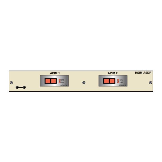
- Page 1 HSIM-A6DP User’s Guide HSIM-A6DP APIM 1 APIM 2...
-
Page 3: Fcc Notice
Only qualified personnel should perform installation procedures. Cabletron Systems reserves the right to make changes in specifications and other information contained in this document without prior notice. The reader should in all cases consult Cabletron Systems to determine whether any such changes have been made. -
Page 4: Doc Notice
IMPORTANT: Before utilizing this product, carefully read this License Agreement. This document is an agreement between you, the end user, and Cabletron Systems, Inc. (“Cabletron”) that sets forth your rights and obligations with respect to the Cabletron software program (the “Program”) contained in this package. - Page 5 Government is subject to restrictions as set forth in subparagraph (c) (1) (ii) of the Rights in Technical Data and Computer Software clause at 252.227-7013. Cabletron Systems, Inc., 35 Industrial Way, Rochester, New Hampshire 03867-0505. HSIM-A6DP User’s Guide...
-
Page 6: Safety Information
Notice CLASS 1 LASER TRANSCEIVERS THE FE-100F3 FAST ETHERNET INTERFACE MODULE, FPIM-05 AND FPIM-07 FDDI PORT INTERFACE MODULES, AND APIM-29 ATM PORT INTERFACE MODULE USE CLASS 1 LASER TRANSCEIVERS. READ THE FOLLOWING SAFETY INFORMATION BEFORE INSTALLING OR OPERATING THESE MODULES. The Class 1 laser transceivers use an optical feedback loop to maintain Class 1 operation limits. -
Page 7: Declaration Of Conformity
Title Rochester, NH, USA ___________________________________ Location HSIM-A6DP User’s Guide 89/336/EEC 73/23/EEC Manufacturer’s Name: Cabletron Systems, Inc. 35 Industrial Way PO Box 5005 Rochester, NH 03867 Mr. J. Solari Cabletron Systems Limited Nexus House, Newbury Business Park London Road, Newbury Berkshire RG13 2PZ, England... - Page 8 Notice HSIM-A6DP User’s Guide...
-
Page 9: Table Of Contents
CHAPTER 1 INTRODUCTION Using This Manual... 1-2 Document Conventions ... 1-2 Overview... 1-3 Features ... 1-3 Specifications ... 1-4 Related Manuals... 1-4 Getting Help... 1-5 CHAPTER 2 INSTALLATION Unpacking the HSIM... 2-1 Installing APIMs... 2-2 Installing an HSIM ... 2-4 2.3.1 Installing an HSIM in an Interface Module ... - Page 10 Contents The ATM Redundancy Configuration Screen ...3-15 3.8.1 ATM Redundancy Configuration Screen Fields ...3-16 3.8.2 Setting the Redundancy Status...3-18 3.8.3 Setting the Primary Port ...3-18 3.8.4 Setting the Active Port...3-18 3.8.5 Setting the Activation of Redundant Port Field...3-19 3.8.6 Setting the Revert to Primary Port Field...3-19 3.8.7 Setting the Periodic Test Status Field ...3-20 3.8.8...
- Page 11 3.18 Enabling the Bandwidth Allocation Mode Feature... 3-54 3.19 Creating PVCs with the Bandwidth Allocation Mode Enabled... 3-57 3.19.1 ATM Connection Setup Screen Fields... 3-58 3.20 The Add/Delete Entry Screen... 3-60 3.20.1 Add/Delete Entry Screen Fields... 3-60 3.20.2 Adding an Entry (PVC) ... 3-62 3.20.3 Modifying an Entry (PVC) ...
- Page 12 Contents HSIM-A6DP User’s Guide...
-
Page 13: Chapter 1 Introduction
• Describes HSIM-A6DP features • Explains how to install the HSIM-A6DP in a Cabletron Systems interface module or standalone hub • Outlines specifications for the Cabletron Systems Asynchronous Transfer Mode (ATM) High Speed Interface Module (HSIM) The HSIM-A6DP provides additional connectivity/functionality to various Cabletron Systems interface modules and standalone hubs. -
Page 14: Using This Manual
Chapter 1: Introduction USING THIS MANUAL Read through this manual completely to familiarize yourself with its content and to gain an understanding of the features and capabilities of the HSIM-A6DP. The following list provides an overview of each section of this manual: Chapter 1, Introduction, outlines the contents of this manual, describes HSIM-A6DP features and concludes with a list of related manuals. -
Page 15: Overview
Specifications, details all of the APIMs available for the HSIM-A6DP. MIB Support For additional information on how to extract and compile individual MIBs, refer to the Release Notes, or contact Cabletron Systems Technical Support (refer to Section LANVIEW Diagnostic LEDs Cabletron Systems provides a visual diagnostic and monitoring system called LANVIEW. -
Page 16: Specifications
Chapter 1: Introduction SPECIFICATIONS This section describes environment specifications and safety requirements for the HSIM-A6DP. Cabletron Systems reserves the right to change these specifications at any time without notice. Environment Operating Temperature: Storage Temperature: Operating Relative Humidity: Regulatory Compliance Safety:... -
Page 17: Getting Help
For additional information about Cabletron Systems or our products, visit our World Wide Web site: http://www.cabletron.com/ For technical support, select Service and Support. Before calling the Cabletron Systems Global Call Center, have the following information ready: • Your Cabletron Systems service contract number •... - Page 18 Chapter 1: Introduction HSIM-A6DP User’s Guide...
-
Page 19: Chapter 2 Installation
Attach the antistatic wrist strap (refer to the instructions on the antistatic wrist strap package). After removing the module from its non-conductive bag, visually inspect the device. If you notice any signs of damage, contact Cabletron Systems Global Call Center immediately. Refer to Section 1.7. HSIM-A6DP User’s Guide... -
Page 20: Installing Apims
Chapter 2: Installation INSTALLING APIMs Only qualified personnel should install or service this unit. To install an APIM into the HSIM-A6DP, refer to Figure 2-2 and perform the following steps: Attach the antistatic wrist strap (refer to the instructions on the antistatic wrist strap package). - Page 21 HSIM Faceplate Screws Press down firmly on the APIM until the pins slide all the way into the connector. Ensure the APIM sits flush on the standoffs. Secure the APIM with the three screws saved in Reattach the faceplate to the HSIM using the three screws saved in Step HSIM-A6DP User’s Guide APIM Screws...
-
Page 22: Installing An Hsim
INSTALLING AN HSIM Only qualified personnel should install or service this unit. You can install an HSIM in any Cabletron Systems device that supports HSIM technology (e.g., 2E42-27, 6E132-25). Refer to the release notes for the version of firmware running on the Cabletron Systems device to ensure that the HSIM-A6DP is supported. - Page 23 Installing an HSIM Standoff Screws Coverplate Faceplate Mounting Screws 207735 Figure 2-3 Removing the HSIM Coverplate HSIM-A6DP User’s Guide...
- Page 24 Chapter 2: Installation Faceplate Mounting Screws Figure 2-4 Installing the HSIM-A6DP Place the HSIM behind the module faceplate. See Insert the connector of the HSIM into the HSIM connector pins on the module. Press down firmly on the back of the HSIM until the pins slide all the way into the connector holes.
-
Page 25: Installing An Hsim In A Standalone Hub
Step 11 ensure that the standoffs on the interface module NOTE align with the standoff screw holes on the HSIM to prevent bending pins. Secure the HSIM to the standoffs with the two screws saved in Reinstall the module in the chassis. Reattach the network cabling to the module. - Page 26 Chapter 2: Installation Step 9 ensure that the standoffs on the hub align with the NOTE standoff screw holes on the HSIM to prevent bending the pins. Press down firmly on the back of the HSIM until the pins slide all the way into the connector holes.
-
Page 27: Chapter 3 Local Management
LOCAL MANAGEMENT This chapter explains how to view current ATM connections, configure Permanent Virtual Channels (PVCs), configure LAN Emulation Clients (LECs), view Emulated LAN (ELAN) properties, perform searches of the HSIM-A6DP LEC ARP Cache, configure bandwidth allocation for PVCs, configure the APIMs installed in the HSIM-A6DP for redundancy, and configure operating parameters for Switched Virtual Channels (SVCs) and LAN Emulation using Local Management. -
Page 28: Local Management Keyboard Conventions
Chapter 3: Local Management LOCAL MANAGEMENT KEYBOARD CONVENTIONS All key names appear in this manual as capital letters. For example, the Enter key appears as ENTER and the Backspace key appears as BACKSPACE. Table 3-1 manual as well as the key functions. Table 3-1 Keyboard Conventions ENTER Key and RETURN Key SPACE Bar and BACKSPACE Key... -
Page 29: Navigating Local Management Screens
NAVIGATING LOCAL MANAGEMENT SCREENS The HSIM-A6DP Local Management application consists of a series of menu screens. Navigate through Local Management by selecting items from the menu screens. HSIM-A6DP Local Management screens. (Standalone Hub View) High Speed HSIM Configuration ATM Screens High Speed Configuration (Interface Module View) - Page 30 Chapter 3: Local Management Using the RETURN Command Use the arrow keys to highlight the RETURN command at the bottom of the Local Management screen. Press ENTER. The previous screen in the Local Management hierarchy displays. The user can also exit Local Management screens by pressing NOTE ESC twice.
-
Page 31: Accessing Local Management
ACCESSING LOCAL MANAGEMENT To access the HSIM-A6DP ATM screen in a standalone hub (e.g., 2E42-27), navigate through the Local Management screens until the High Speed Configuration screen displays. Select HSIM from the High Speed Configuration screen and press ENTER. The HSIM-A6DP ATM screen displays. -
Page 32: The Hsim-A6Dp Atm Screen
Chapter 3: Local Management THE HSIM-A6DP ATM SCREEN The HSIM-A6DP ATM screen displays four menu items for configuration and monitoring of the HSIM-A6DP. The following list explains each of the HSIM-A6DP ATM screen fields: CONNECTIONS This menu item allows the user to view the current configured virtual connections (PVCs and SVCs) of the HSIM-A6DP. -
Page 33: The Atm Connections Screen
The DISCOVERY ELAN SETUP menu item will display only if NOTE the host device has been set to operate as a SecureFast switch. Refer to the Local Management chapter of the host device for instructions on configuring the host device for this type of operation. -
Page 34: Atm Connections Screen Fields
Chapter 3: Local Management 3.5.1 ATM Connections Screen Fields The ATM Connections screen allows the user to open the ATM Connections Setup screen, and to set the Bandwidth Allocation Mode to on or off. The following list explains each of the ATM Connections screen fields: CONNECTION TABLE This menu item, when selected, opens the ATM Connection Setup screen. -
Page 35: The Atm Connection Setup Screen
THE ATM CONNECTION SETUP SCREEN To access the ATM Connection Setup screen from the ATM Connections screen, perform the following steps: Use the arrow keys to highlight the CONNECTION TABLE menu item on the ATM Connections screen. Press ENTER. The ATM Connection Setup screen, displays. -
Page 36: Atm Connection Setup Screen Fields
Chapter 3: Local Management 3.6.1 ATM Connection Setup Screen Fields The first two connections shown in NOTE values of 0, 5 and 0,16 respectively) represent ILMI and UNI. These two connections, even if they are disabled in the Signalling screen ATM Connection Setup screen. - Page 37 Encapsulation Type (Read-Only) This field displays the type of Encapsulation being used to switch Ethernet frames to ATM cells. The three possible options for this field are as follows: • VC Mux 802.3 LANE - Emulation. This method is specified by the ATM Forum LAN Emulation specification.
-
Page 38: The Add/Delete Entry Screen
Chapter 3: Local Management THE ADD/DELETE ENTRY SCREEN To access the Add/Delete Entry screen from the ATM Connection Setup screen perform the following steps: Use the arrow keys to highlight the ADD/DELETE command at the bottom of the ATM Connection Setup screen. Press ENTER, the Add/Delete Entry screen, INTERFACE 25 ATM Add/Delete Entry Device Name:6E132-25... -
Page 39: Adding An Entry (Pvc)
Encapsulation Type (Toggle) This field displays the type of data encapsulation that the HSIM-A6DP will use to perform LAN to ATM translation. This field toggles between the following options: • VC Mux 802.3 Bridged - Protocols as defined by the IETF RFC 1483. •... -
Page 40: Modifying An Entry (Pvc)
Chapter 3: Local Management 3.7.3 Modifying an Entry (PVC) To modify an existing entry (PVC), perform the following steps: Use the arrow keys to highlight the VPI field, and enter the new VPI value. Use the arrow keys to highlight the VCI field and enter the new VCI value;... -
Page 41: The Atm Redundancy Configuration Screen
THE ATM REDUNDANCY CONFIGURATION SCREEN There MUST be two APIMs installed in the HSIM-A6DP for the NOTE redundancy feature to be available. To access the ATM Redundancy Configuration screen from the ATM screen, perform the following steps: Use the arrow keys to highlight the APIM REDUNDANCY menu item from the ATM screen. -
Page 42: Atm Redundancy Configuration Screen Fields
Chapter 3: Local Management 3.8.1 ATM Redundancy Configuration Screen Fields The ATM Redundancy Configuration screen allows the user to perform the following tasks: • To enable or disable the redundancy feature of the HSIM-A6DP. • To set which port (APIM) is the primary port of the HSIM-A6DP. •... - Page 43 Active Port (Read-Only) This field displays which APIM is currently acting as the active port for the HSIM-A6DP. The Active port field displays 1 or 2. Activation of redundant port (Toggle) This field allows the user to configure how the HSIM-A6DP will activate the redundant port if a problem arises with the primary port.
-
Page 44: Setting The Redundancy Status
Chapter 3: Local Management TEST PORTS NOW (Command) This command, when performed, instructs the HSIM-A6DP to perform an APIM redundancy test immediately. When the test is completed, the results are displayed in the Results of previous test field. RESET TO FACTORY DEFAULTS (Command) This command, when performed, resets all the fields in the ATM Redundancy Configuration screen to their default settings. -
Page 45: Setting The Activation Of Redundant Port Field
Use the arrow keys to highlight the SAVE command at the bottom of the screen and press ENTER. The changes are saved to memory. 3.8.5 Setting the Activation of Redundant Port Field To set the Activation of redundant port field (automatic or manual), perform the following steps: Use the arrow keys to highlight the Activation of redundant port field. -
Page 46: Setting The Periodic Test Status Field
Chapter 3: Local Management 3.8.7 Setting the Periodic Test Status Field To enable or disable the Periodic test status feature, perform the following steps: Use the arrow keys to highlight the Periodic test status field. Press the SPACE bar to toggle between the choices until the desired mode displays ([Enabled] or [Disabled]). -
Page 47: Using The Test Ports Now Command
3.8.9 Using the TEST PORTS NOW Command To force the HSIM-A6DP to perform a redundancy test immediately, perform the following steps: Use the arrow keys to highlight the TEST PORTS NOW command. Press ENTER. The HSIM-A6DP performs the redundancy test, and displays the results in the Result of previous test field. -
Page 48: The Atm Lec Screen
Chapter 3: Local Management THE ATM LEC SCREEN To access the ATM LEC screen from the ATM screen, perform the following steps: Use the arrow keys to highlight the LAN EMULATION CLIENTS menu item. Press ENTER. The ATM LEC screen, Device Name:6E132-25 Slot Number: X Figure 3-7 The ATM LEC Screen... -
Page 49: Atm Lec Screen Fields
The ATM LEC Screen 3.9.1 ATM LEC Screen Fields The ATM LEC screen contains four menu items that open Local Management screens used to create, maintain, and monitor LAN Emulation Clients (LECs). It also allows the user to search the ARP cache for specific MAC addresses. -
Page 50: The Atm Lec Table Screen
Chapter 3: Local Management 3.10 THE ATM LEC TABLE SCREEN To access the ATM LEC Table screen from the ATM LEC screen, perform the following steps: Use the arrow keys to highlight the LEC TABLE menu item on the ATM LEC screen. Press ENTER. -
Page 51: Atm Lec Table Screen Fields
3.10.1 ATM LEC Table Screen Fields The ATM LEC Table screen is a read-only screen that allows the user to view the status of all LECs currently configured on the HSIM-A6DP. The following list explains each of the ATM LEC Table screen fields: IF (Read-Only) This field displays the MIB-II Interface that this LEC has been assigned dynamically. - Page 52 Chapter 3: Local Management The initialRegistration phase is used by the LEC to initialRegistration - confirm that its MAC Address(es) are unique before becoming fully operational on the network. While in the busConnect phase, the LEC connects to the busConnect - Broadcast and Unknown server (BUS).
-
Page 53: The Lec Administration Screen
3.11 THE LEC ADMINISTRATION SCREEN Although the following screen reads “ELAN NOTE ADMINISTRATION” this screen is used for LAN Emulation Client (LEC) Administration. In this section, the screen is referred to as the “LEC Administration screen”. To access the LEC Administration screen from the ATM screen, perform the following steps: Use the arrow keys to highlight the LEC ADMINISTRATION menu item from the ATM screen. -
Page 54: Lec Administration Screen Fields
Chapter 3: Local Management 3.11.1 LEC Administration Screen Fields The LEC Administration screen allows the user to add/modify or delete LAN Emulation Clients (LECs). New LECs can be configured by the user, or this function can be performed automatically by the HSIM-A6DP. The following list explains each of the LEC Administration screen fields and commands: LEC Index (Modifiable) - Page 55 LAN Type (Read-Only) This field displays the type of ELAN that this LEC joins. This field is read-only and displays [802.3]. This is the only type of ELAN currently supported by the HSIM-A6DP. LES ATM Address (Modifiable) This field displays the address of the LAN Emulation Server with which the LEC registers.
-
Page 56: Changing The Lec Status (Modify Mode Only)
Chapter 3: Local Management 3.11.2 Changing the LEC Status (MODIFY MODE Only) To change the LEC Status, perform the following steps: Use the arrow keys to highlight the MODIFY MODE command at the bottom of the screen and press ENTER. Use the arrow keys to highlight the LEC Index field. -
Page 57: Configuring The Lec Manually (Create Mode Only)
Use the arrow keys to highlight the LECS ATM Address field. Enter the ATM Address of the LECS. This step is optional, and should be performed only when a specific LECS, out of multiple servers, is desired for this LEC. Use the arrow keys to highlight the ADD LEC command at the bottom of the screen and press ENTER. -
Page 58: Modifying An Existing Lec
Chapter 3: Local Management Enter the LES ATM Address in the field. Ensure that a valid ATM address is used If there is more than one LECS present on the network, and a specific LECS is desired for this LEC, perform the substeps that follow. -
Page 59: Deleting An Existing Lec
Use the arrow keys to highlight the SAVE command at the bottom of the screen and press ENTER. The modified LEC is now entered into the HSIM-A6DP LEC Index. 3.11.6 Deleting an Existing LEC To delete an existing LEC, perform the following steps: Use the arrow keys to highlight the LEC Index field. -
Page 60: Elan Properties Screen Fields
Chapter 3: Local Management 3.12 THE ELAN PROPERTIES SCREEN To access the ELAN Properties screen from the ATM LEC screen, perform the following steps: Use the arrow keys to highlight the LEC PROPERTIES menu item of the ATM LEC screen. Press ENTER;... - Page 61 LEC ID (Read-Only) The LEC ID displays the LAN Emulation Client Identifier assigned to this LEC by the LAN Emulation Server when the LEC was created. If the LEC ID field reads “0” it signifies that this LEC is not a member of an emulated LAN, and is not connected to a LAN Emulation Server.
- Page 62 Chapter 3: Local Management LECS ATM ADDR (Read-Only) This field displays the ATM address of the LAN Emulation Configuration Server. If this LEC was configured manually, this field can be empty. LES ATM ADDR (Read-Only) This field displays the ATM Address of the LAN Emulation Server to which the LEC is connected.
-
Page 63: The Lec Arp Cache Screen
PREV (Command) This command lets you scroll to the previous screen. To go to the previous screen use the arrow keys to highlight the PREV command and press ENTER. The previous ELAN Properties screen displays. 3.13 THE LEC ARP CACHE SCREEN The LEC ARP Cache screen allows the user to view the ATM address, VPI and VCI used to communicate with a MAC address. -
Page 64: Lec Arp Cache Screen Fields
Chapter 3: Local Management 3.13.1 LEC ARP CACHE Screen Fields The following explains each of the LEC ARP Cache screen fields: LEC Index (Modifiable) This field displays the Index of the LEC to which the information displayed on the screen pertains. To select a new LEC Index, use the arrow keys to highlight the LEC Index option and press the SPACE bar to move through the available LECs. - Page 65 The LEC ARP Cache Screen NEXT (Command) This command opens the next series of MAC/ATM Address pairs. To access the next series of address pairs, highlight the NEXT command by using the arrow keys and pressing ENTER. The next series of MAC/ATM address pairs displays.
-
Page 66: The Lec Arp Cache Search Screen
Chapter 3: Local Management 3.14 THE LEC ARP CACHE SEARCH SCREEN The LEC ARP Cache screen allows the user to search the HSIM-A6DP LEC ARP Cache for a specific MAC Address. If a match is found, the screen will display the ATM Address of the LEC to which the MAC Address is bound, the ELAN name to which the LEC belongs, and the VPI and VCI being used by the LEC to connect to the listed ATM Address. -
Page 67: Lec Arp Cache Search Screen Fields
3.14.1 LEC ARP Cache Search Screen Fields The following explains each of the LEC ARP Cache Search screen fields: MAC Address (Modifiable) This field is used to enter the MAC Address for which you wish to search. LEC Index (Modifiable) This field is used to select the LEC Index to which you wish to perform the search. - Page 68 Chapter 3: Local Management When the search is completed, the following information displays: Module Name:6E132-25 Slot Number: X MAC Address: 00-00-1d-12-34-56 ATM Address: 0000.0000.00.000000.0000.0000.0000.000000000000.00 ELAN Name: CTRON VPI, VCI: IF: 31 LEC Index: 1 Figure 3-13 LEC ARP Cache Search Results The following describes the read-only results that display after a successful LEC ARP Cache search: If the LEC ARP Cache search is unsuccessful, the screen...
- Page 69 The LEC ARP Cache Search Screen ELAN Name (Read-Only) This field displays the name of the ELAN to which this LEC belongs. VPI, VCI (Read-Only) This field displays the VPI and VCI that the MAC address is currently using. IF (Read-Only) This field displays the MIB-II interface that the associated MAC address is using.
-
Page 70: The Signalling Screen
Chapter 3: Local Management 3.15 THE SIGNALLING SCREEN To access the Signalling screen from the ATM screen, perform the following steps: Use the arrow keys to highlight the SIGNALLING menu item of the ATM Screen. Press ENTER; the Signalling screen, Module Name:6E132-25 Slot Number: X ILMI Status:... -
Page 71: Signaling Screen Fields
The Signalling Screen 3.15.1 Signaling Screen Fields The Signaling screen allows the user to set the parameters for all SVCs, to view the Interim Local Management Interface (ILMI) Physical Address, view the current version of UNI being used by the HSIM-A6DP, to disable ILMI and UNI, and to restart ILMI and UNI. -
Page 72: Changing The Ilmi Status
HSIM-A6DP. This field is modifiable if signaling is enabled manually by the user. In autoconfigure mode the HSIM-A6DP uses either UNI 3.0 or UNI 3.1, depending on the version of UNI being used by the ATM switch to which the HSIM-A6DP is connected. -
Page 73: Disabling The Ilmi Status
NOTE HSIM-A6DP to use a desired version of UNI, rather than having the HSIM-A6DP use the version of UNI that the ATM switch to which it is connected is currently using. Use the arrow keys to highlight the UNI Version field. -
Page 74: Changing The Uni Status
Chapter 3: Local Management 3.15.4 Changing the UNI Status To change the UNI status from the default state of [Enabled] perform the following steps: Use the arrow keys to highlight the UNI Status field. Press the SPACE bar until the option [Disabled] displays. Before completing the following step, ensure that this caution is fully understood. -
Page 75: Setting The Uni Version
3.15.7 Setting the UNI Version To set the UNI Version manually, perform the following steps: Use the arrow keys to highlight the ILMI Status field. Press the SPACE bar until the option [Enabled] displays. Use the arrow keys to highlight the UNI Version field. Press the SPACE bar to toggle between the selections [UNI3.0] and [UNI3.1]. -
Page 76: The Discovery Elan Setup Screen
The DISCOVERY ELAN SETUP menu item will display only if NOTE the host device has been set to operate as a SecureFast switch. Refer to the Local Management chapter of the host device for instructions on configuring the host device for this type of operation. -
Page 77: Atm Discovery Elan Setup Screen Fields
3.16.1 ATM Discovery ELAN Setup Screen Fields The ATM Discovery ELAN Setup screen is used only when the host device is configured to operate as a SecureFast switch. Upon first initialization, the HSIM-A6DP attempts to contact any other HSIM-A6DPs present on the SecureFast network. Once all HSIM-A6DPs have discovered each other, they automatically create a default discovery ELAN. -
Page 78: Assigning The Hsim-A6Dp To A Discovery Elan
Chapter 3: Local Management ELAN Name (Modifiable) This field is used to enter the name of the discovery ELAN that the HSIM-A6DP will join, when the discovery ELAN becomes enabled. Mode (Toggle) This field toggles between “Master” and “Slave”. This field currently does not have any effect on the discovery ELAN, and any saved changes will not affect network performance. - Page 79 Use the arrow keys to highlight the Status field. Press the SPACE bar until the desired mode displays (Enabled or Disabled). If you do not want the HSIM-A6DP to join the ELAN NOTE immediately, the Status field may be set to “Disabled”. When you wish the HSIM-A6DP to join the ELAN, enter this screen and toggle the Status field to “Enabled”...
-
Page 80: Using The Bandwidth Allocation Mode Feature
Chapter 3: Local Management 3.17 USING THE BANDWIDTH ALLOCATION MODE FEATURE The HSIM-A6DP provides a feature that allows the user to create PVCs, and configure each PVC to be guaranteed a set amount of bandwidth, up to the amount of bandwidth that the APIM provides. Up to 1020 PVCs may be created using the Bandwidth NOTE Allocation feature. - Page 81 Enabling the Bandwidth Allocation Mode Feature Device Name:6E132-25 Slot Number: X SAVE Figure 3-16 The ATM Connection Screen Use the arrow keys to highlight the Bandwidth Allocation Mode field. Press the SPACE bar until [ON] displays. Use the arrow keys to highlight the SAVE command at the bottom of the screen.
- Page 82 Chapter 3: Local Management Device Name:6E132-25 Slot Number: X YOU HAVE ELECTED TO ENABLE BANDWIDTH ALLOCATION MODE. THIS WILL DELETE ALL LECs AND PVCs CURRENTLY CONFIGURED ON THIS DEVICE. UNI AND ILMI WILL BE DISABLED. ARE YOU SURE YOU WANT TO ENABLE BW ALLOCATION MODE? Figure 3-17 The Bandwidth Allocation Mode Warning Screen Do not perform the following steps unless the Bandwidth Allocation Mode Warning screen is fully understood.
-
Page 83: Creating Pvcs With The Bandwidth Allocation Mode Enabled
Creating PVCs with the Bandwidth Allocation Mode Enabled 3.19 CREATING PVCS WITH THE BANDWIDTH ALLOCATION MODE ENABLED After the Bandwidth Allocation Mode has been enabled and saved, Local Management returns the user to the ATM Connections screen; refer to Figure 3-16. -
Page 84: Atm Connection Setup Screen Fields
Chapter 3: Local Management 3.19.1 ATM Connection Setup Screen Fields The first two connections shown in NOTE values of 0, 5 and 0,16 respectively) represent ILMI and UNI. These two connections, although disabled by the Bandwidth Allocation feature, will always display on the ATM Connection Setup screen. - Page 85 Creating PVCs with the Bandwidth Allocation Mode Enabled Encapsulation Type (Read-Only) This field displays the type of Encapsulation being used to switch Ethernet frames to ATM cells. The two possible options for this field are as follows: • VC Mux 802.3 Bridged - Protocols as defined by the IETF RFC 1483.
-
Page 86: The Add/Delete Entry Screen
Chapter 3: Local Management 3.20 THE ADD/DELETE ENTRY SCREEN To access the Add/Delete Entry screen from the ATM Connection Setup screen perform the following steps: Use the arrow keys to highlight the ADD/DELETE command at the bottom of the ATM Connection Setup screen. Press ENTER, the Add/Delete Entry screen, INTERFACE 25 ATM Add/Delete Entry Device Name:6E132-25... - Page 87 VPI (Modifiable) This field is used to enter the Virtual Path Identifier of the PVC. The available range for this field is 0 or 1, with a default value of 0. VCI (Modifiable) This field is used to enter the Virtual Channel Identifier of the PVC. The available range for this field is 32 through 1020.
-
Page 88: Adding An Entry (Pvc)
Chapter 3: Local Management DELETE (Command) This command appears only if a valid VCI has been entered in the VCI field of the Add/Delete Entry screen. This command deletes the PVC from the HSIM-A6DP connection table. 3.20.2 Adding an Entry (PVC) To add an entry (PVC), perform the following steps: Use the arrow keys to highlight the IF field and enter the MIB-II interface number to which the PVC will be added. -
Page 89: Modifying An Entry (Pvc)
3.20.3 Modifying an Entry (PVC) To modify an existing entry (PVC), perform the following steps: Use the arrow keys to highlight the IF field and enter the IF value that you want to change. Use the arrow keys to highlight the VPI field and enter the VPI value that you want to change. -
Page 90: Deleting An Entry (Pvc)
Chapter 3: Local Management 3.20.4 Deleting an Entry (PVC) To delete an entry (PVC), perform the following steps: Use the arrow keys to highlight the VPI field and enter the VPI of the PVC that you want to delete. Use the arrow keys to highlight the VCI field and enter the VCI of the PVC that you want to delete. -
Page 91: Lanview Leds
This chapter describes how to use the LANVIEW LEDs to monitor HSIM status and diagnose HSIM problems. LANVIEW LEDs (Transmit, Receive, STS and LNK). The terms flashing, blinking, and solid used in the LED NOTE definition tables of this chapter indicate the following: Flashing indicates an irregular LED pulse. - Page 92 Systems Global Call Center. Refer to Section APIM should be replaced. The APIM will still function, but packet switching performance may be affected. If the APIM goes into this LED state (Blinking) contact Cabletron Systems Global Call Center. Refer to Getting 1.7, Getting Help. Section 1.7,...
-
Page 93: A.1 Apim-11 Specifications
APIM SPECIFICATIONS This appendix provides specifications for Cabletron Systems ATM Port Interface Modules (APIMs). APIM-11 SPECIFICATIONS Physical Interface: Media Type: Data Rate: Connector Type: Transmit Power: Receive Sensitivity: Loss Budget: Wavelength: Typical Link Distance: HSIM-A6DP User’s Guide APPENDIX A TAXI... -
Page 94: A.2 Apim-21 Specifications
Appendix A: APIM Specifications APIM-21 SPECIFICATIONS Physical Interface: Media Type: Data Rate: Connector Type: Transmit Power: Receive Sensitivity: Loss Budget: Wavelength: Typical Link Distance: Multimode Fiber 155 Mbps -14db to -18.5db -14db to -32.5db -14db to -18.5db 1270 nm to 1380 nm 2 km Figure A-2 The APIM-21 HSIM-A6DP User’s Guide... -
Page 95: A.3 Apim-29 Specifications
APIM-29 SPECIFICATIONS Physical Interface: Media Type: Data Rate: Connector Type: Transmit Power: Receive Sensitivity: Loss Budget: Wavelength: Typical Link Distance: HSIM-A6DP User’s Guide Single Mode Fiber 155 Mbps -8db to -14db -6db to -32.5db -8db to -24.5db 1261 nm to 1360 nm 25 km Figure A-3 The APIM-29 APIM-29 Specifications... -
Page 96: Apim-29Lr Specifications
Appendix A: APIM Specifications APIM-29LR SPECIFICATIONS Physical Interface: Media Type: Data Rate: Connector Type: Transmit Power: Receive Sensitivity: Loss Budget: Wavelength: Typical Link Distance: Single Mode Fiber 155 Mbps 0db to -5db -31db -26db to -31db 1280 nm to 1335 nm 60 km Figure A-4 The APIM-29LR HSIM-A6DP User’s Guide... -
Page 97: A.5 Apim-22 Specifications
APIM-22 SPECIFICATIONS Physical Interface: Media Type: Data Rate: Connector Type: Typical Link Distance: The APIM-22R is considered an ATM User Device and therefore has a different signal pin assignment than the ATM Network Equipment as specified by the ATM Forum User-Network Interface (UNI) specification. Figure A-5 shows the pin assignments for the APIM-22R. -
Page 98: A.6 Apim-67 Specifications
T1.404-1989 Carrier-to-Customer Installation-DS3 Metallic Interface Specification, Section 5.12 Grounding Arrangements. In accordance with this specification, each channel (Transmit and Receive) must be grounded at one end. Cabletron Systems ships the APIM-67R with the following default jumper settings: • Receive channel jumper - grounded •... - Page 99 APIM-67 Specifications RECEIVE CHANNEL JUMPER (GROUNDED) TRANSMIT CHANNEL JUMPER (NOT GROUNDED) 142910 Figure A-6 APIM-67R Default Jumper Settings Figure A-7 The APIM-67 HSIM-A6DP User’s Guide...
- Page 100 Appendix A: APIM Specifications HSIM-A6DP User’s Guide...
Need help?
Do you have a question about the HSIM HSIM-A6DP- and is the answer not in the manual?
Questions and answers