Table of Contents
Advertisement
Quick Links
Advertisement
Table of Contents

Related Manuals for Cabletron Systems BRIM F6 BRIM-F6


Summary of Contents for Cabletron Systems BRIM F6 BRIM-F6
- Page 1 HSIM-F6 User’s Guide HSIM-F6...
-
Page 3: Fcc Notice
Only qualified personnel should perform installation procedures. Cabletron Systems reserves the right to make changes in specifications and other information contained in this document without prior notice. The reader should in all cases consult Cabletron Systems to determine whether any such changes have been made. -
Page 4: Doc Notice
IMPORTANT: Before utilizing this product, carefully read this License Agreement. This document is an agreement between you, the end user, and Cabletron Systems, Inc. (“Cabletron”) that sets forth your rights and obligations with respect to the Cabletron software program (the “Program”) contained in this package. - Page 5 Government is subject to restrictions as set forth in subparagraph (c) (1) (ii) of the Rights in Technical Data and Computer Software clause at 252.227-7013. Cabletron Systems, Inc., 35 Industrial Way, Rochester, New Hampshire 03867-0505. HSIM-F6 User’s Guide...
-
Page 6: Safety Information
Notice CLASS 1 LASER TRANSCEIVERS THE FE-100F3 FAST ETHERNET INTERFACE MODULE, FPIM-05 AND FPIM-07 FDDI PORT INTERFACE MODULES, AND APIM-29 ATM PORT INTERFACE MODULE USE CLASS 1 LASER TRANSCEIVERS. READ THE FOLLOWING SAFETY INFORMATION BEFORE INSTALLING OR OPERATING THESE ADAPTERS. The Class 1 laser transceivers use an optical feedback loop to maintain Class 1 operation limits. -
Page 7: Declaration Of Conformity
Title Rochester, NH, USA ___________________________________ Location HSIM-F6 User’s Guide 89/336/EEC 73/23/EEC Manufacturer’s Name: Cabletron Systems, Inc. 35 Industrial Way PO Box 5005 Rochester, NH 03867 Mr. J. Solari Cabletron Systems Limited Nexus House, Newbury Business Park London Road, Newbury Berkshire RG13 2PZ, England... - Page 8 Notice HSIM-F6 User’s Guide...
-
Page 9: Table Of Contents
CHAPTER 1 INTRODUCTION Using This Manual... 1-2 Document Conventions ... 1-2 Getting Help... 1-3 Overview... 1-4 1.4.1 Features... 1-4 Specifications ... 1-5 Related Documentation ... 1-6 CHAPTER 2 INSTALLATION Unpacking the HSIM... 2-1 Installing FPIMs ... 2-2 Installing an HSIM ... 2-4 2.3.1 Installing an HSIM in an Interface Module ... - Page 10 Contents The Full Duplex Configuration Screen ...3-23 3.9.1 Full Duplex FDDI ...3-24 3.9.2 Full Duplex Configuration Screen Fields ...3-25 3.9.3 Configuring the HSIM-F6 for Full Duplex Operation...3-26 3.10 The FDDI/Ethernet Translation Configuration Screen ...3-27 3.10.1 FDDI Translation Configuration Screen Fields...3-28 3.10.2 Setting Frame Translation Types ...3-30 3.10.3 Setting the Frame Translation Types to the Default Values ...3-31...
-
Page 11: Chapter 1 Introduction
Welcome to the Cabletron Systems HSIM-F6 User’s Guide. This manual provides the following information: • Describes HSIM-F6 features. • Explains how to install the HSIM-F6 in a Cabletron Systems interface module or standalone hub. • Explains how to configure and monitor the HSIM-F6 through Local Management. -
Page 12: Using This Manual
Chapter 1: Introduction USING THIS MANUAL Read through this manual completely to familiarize yourself with its content and to gain an understanding of the features and capabilities of the HSIM-F6. The following list provides an overview of each section of this manual: Chapter 1, Introduction, outlines the contents of this manual, describes... -
Page 13: Getting Help
For additional information about Cabletron Systems or our products, visit our World Wide Web site: http://www.cabletron.com/ For technical support, select Service and Support. Before calling the Cabletron Systems Global Call Center, have the following information ready: • Your Cabletron Systems service contract number •... -
Page 14: Overview
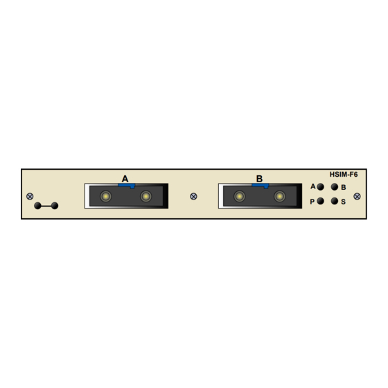
Chapter 1: Introduction OVERVIEW The HSIM-F6 extends the functionality of certain Cabletron Systems interface modules or standalone hubs to include high-speed uplink capability. The HSIM-F6 allows remote connectivity using FDDI technology. 1.4.1 Features Connectivity The HSIM-F6 is equipped with slots for FDDI A and B ports. These two ports allow connection to the ring as a Dual Attached Station (DAS) using two FPIMs or as a Single Attached Station (SAS) using one FPIM. -
Page 15: Specifications
FDDI ring status. LANVIEW LEDs, provides information on all HSIM-F6 LEDs. SPECIFICATIONS This section describes environment specifications and safety requirements for the HSIM-F6. Cabletron Systems reserves the right to change these specifications at any time without notice. Environment Operating Temperature: Storage Temperature:... -
Page 16: Related Documentation
HSIM-F6. The manuals referenced above can be obtained on the World Wide Web in Adobe Acrobat Portable Document Format (PDF) at the following site: http://www.cabletron.com/ These manuals are also available on the Cabletron Systems Hardware Manuals CD-ROM. HSIM-F6 User’s Guide... -
Page 17: Chapter 2 Installation
User’s Guide. After removing the module from its non-conductive bag, visually inspect the device. If you notice any signs of damage, contact Cabletron Systems Global Call Center immediately. Refer to Section 1.3, Getting Help, for instructions. -
Page 18: Installing Fpims
Chapter 2: Installation INSTALLING FPIMs Only qualified personnel should install or service this unit. The HSIM-F6 and FPIMs are sensitive to static discharges. Use a grounding strap and observe all static precautions during this procedure. Failure to do so could result in damage to the CAUTION HSIM-F6 or the FPIMs. - Page 19 FPIM Coverplate HSIM Standoffs Figure 2-1 Removing the FPIM Coverplate HSIM Faceplate Screws HSIM-F6 User’s Guide Standoff Screws FPIM Screws FPIM Connector Standoffs 209134 Figure 2-2 Installing FPIMs Installing FPIMs HSIM FPIM Connector Pins...
-
Page 20: Installing An Hsim
INSTALLING AN HSIM Only qualified personnel should install or service this unit. You can install an HSIM in any Cabletron Systems device that supports HSIM technology (e.g., 2E42-27, 6E132-25). Refer to the release notes for the version of firmware running on the Cabletron Systems device to ensure that the HSIM-F6 is supported. - Page 21 Slide out the module, and place it on its side with the internal components facing up. Refer to Figure 2-3 and the HSIM coverplate. Save the screws. Refer to Figure 2-3 screws. Coverplate Faceplate Mounting Screws Figure 2-3 Removing the HSIM Coverplate Refer to Figure 2-4 Align the HSIM connector of the HSIM-F6 into the HSIM pins on the...
- Page 22 Chapter 2: Installation Press down firmly on the back of the HSIM until the pins slide all the way into the HSIM Connector. Ensure that the standoffs on the interface module align with the NOTE standoff screw holes on the HSIM. Secure the HSIM-F6 to the module faceplate using the mounting screws saved in step...
-
Page 23: Installing An Hsim In A Standalone Hub
HSIM Faceplate Mounting Screws Figure 2-4 Installing the HSIM-F6 2.3.2 Installing an HSIM in a Standalone Hub To install an HSIM-F6 into a standalone hub (e.g. 2E42-27), perform the following steps: Power down the hub and remove the power cord. Note the ports that have cables attached to them. - Page 24 Chapter 2: Installation Attach the antistatic wrist strap (refer to the instructions outlined on the antistatic wrist strap package). Remove the hub chassis cover (refer to your specific hub documentation for instructions on removing the hub chassis cover). Refer to Figure 2-3 and the HSIM coverplate.
-
Page 25: Chapter 3 Local Management
LOCAL MANAGEMENT This chapter provides instructions on configuring the HSIM-F6 to operate in full duplex FDDI mode, viewing HSIM-F6 FDDI statistics, translating specific FDDI frame types to specific Ethernet frame types and to viewing the FDDI ring topology using Local Management. When installed, the HSIM-F6 provides additional Local NOTE Management features. -
Page 26: Local Management Keyboard Conventions
Chapter 3: Local Management LOCAL MANAGEMENT KEYBOARD CONVENTIONS All key names appear in this manual as capital letters. For example, the Enter key appears as ENTER and the Backspace key appears as BACKSPACE. Table 3-1 manual as well as the key functions. Table 3-1 Keyboard Conventions ENTER Key and RETURN Key SPACE Bar and BACKSPACE Key... -
Page 27: Selecting Local Management Menu Screen Items
3.1.1 Selecting Local Management Menu Screen Items Select items on a menu screen by performing the following steps: Use the arrow keys to highlight a menu item. Press ENTER. The selected menu item displays on the screen. 3.1.2 Exiting Local Management Screens Exit Local Management using the methods described below: Using the EXIT Command To exit an LM screen using the EXIT command, proceed as follows:... -
Page 28: Navigating Local Management Screens
Chapter 3: Local Management NAVIGATING LOCAL MANAGEMENT SCREENS The HSIM-F6 Local Management application consists of a series of menu screens. Navigate through Local Management by selecting items from the menu screens. Figure 3-1 Management screens. High Speed (Standalone Hub View) Configuration High Speed (Interface Module View) - Page 29 Device Name: 6E132-25 Slot Number: X Figure 3-2 The HSIM-F6 Setup Screen The HSIM-F6 Setup screen displays five menu items for accessing Local Management screens that allow further configuring and monitoring of the HSIM-F6 and the FDDI ring. The following list explains each of the HSIM-F6 Setup screen menu items: HSIM-F6 Statistics Select this menu item to display the HSIM-F6 Statistics screen.
- Page 30 Chapter 3: Local Management HSIM-F6 Configuration Select this menu item to display the HSIM-F6 Configuration screen. This screen allows the user to view the operating requirements that the HSIM-F6 advertises to all other stations when it first enters the FDDI ring and to set the interval that the HSIM-F6 sends Neighbor Information Frames (NIFs).
-
Page 31: The Hsim-F6 Statistics Screen
THE HSIM-F6 STATISTICS SCREEN To access the HSIM-F6 Statistics screen from the HSIM-F6 Setup screen, perform the following steps: Use the arrow keys to highlight the HSIM-F6 Statistics menu item on the HSIM-F6 Setup screen. Press ENTER. The HSIM-F6 Statistics screen, Device Name: 6E132-25 Slot Number: X Figure 3-3 The HSIM-F6 Statistics Screen... -
Page 32: Hsim-F6 Statistics Screen Fields
Chapter 3: Local Management 3.4.1 HSIM-F6 Statistics Screen Fields The HSIM-F6 Statistics screen allows the user to open screens that display the current HSIM-F6 operational status. The definitions for the HSIM-F6 Statistics screen menu items are as follows: MIB-II STATISTICS When selected, this menu item opens the MIB-II Interface Statistics screen. -
Page 33: Mib-Ii Interface Statistics Screen Fields
The MIB-II Statistics Screen 3.5.1 MIB-II Interface Statistics Screen Fields The following list describes the MIB-II Statistics screen fields: IN OCTETS This field displays the number of octets (bytes) received by the HSIM-F6. IN UNICAST PKTS This field displays the number of unicast packets (packets destined for one specific address) received by the HSIM-F6. -
Page 34: Clear Counters
Chapter 3: Local Management OUT ERRORS This field displays the total number of errors (of any type) transmitted by the HSIM-F6. CLEAR COUNTERS The Clear Counters command resets all counters within the MIB-II Statistics screen to zero. To reset all the counters use the arrow keys to highlight the CLEAR COUNTERS field and press ENTER. -
Page 35: Hsim-F6 Fddi Ring Statistics Screen Fields
3.6.1 HSIM-F6 FDDI Ring Statistics Screen Fields The HSIM-F6 FDDI Ring Statistics screen allows the user to monitor the current HSIM-F6 operational status. The following list describes the Ring Statistics screen fields: RING STATE Displays the current ring state. The possible ring states are as follows: •... -
Page 36: Mac Configuration
Chapter 3: Local Management MAC CONFIGURATION The MAC Configuration field describes the current configuration of the Media Access Control (MAC) and physical layers of the A and B ports. The possible port configurations are as follows: The flow of the primary ring is entering the MAC from •... - Page 37 The flow of the primary ring is entering through port A • Wrap-A - (primary in) and is wrapped by the MAC, causing the ring to exit through port A (secondary out). Port B is disconnected from the ring. If the HSIM-F6 MAC Configuration reads “Wrap-A” the ring has lost the redundancy of the secondary ring due to the wrapped condition.
- Page 38 Chapter 3: Local Management The flow of the primary ring is entering through port B • Wrap-B - (secondary in) and is wrapped by the MAC, causing the ring to exit through port B (primary out). Port A is disconnected from the ring. If the HSIM-F6 MAC Configuration reads “Wrap-B”...
- Page 39 The flow of the primary ring is entering through port A • Wrap-AB - (primary in) and is wrapped by the MAC, causing the ring to exit through port A (secondary out). The MAC has also wrapped port B, causing the flow of the ring to enter through port B (secondary in) and exit through port B (primary out).
-
Page 40: The Ring Map Configuration Screen
Chapter 3: Local Management THE RING MAP CONFIGURATION SCREEN The Ring Map Configuration screen displays FDDI formatted addresses of ring stations in a graphic illustration of the FDDI ring topology, and provides access to a Node Information screen for each device located on the ring. -
Page 41: Ring Map Configuration Screen Fields
3.7.1 Ring Map Configuration Screen Fields The Ring Map Configuration screen displays the addresses and sequence of each FDDI device attached to the ring. When first displayed, the station at the upper left corner of the ring is this station (HSIM-F6). The Ring Map Configuration screen displays node class, node address, and twisted and/or wrapped conditions (T for twisted and/or W for wrapped) in parentheses. -
Page 42: Ring Map Configuration Screen Commands
The following list describes each of the Ring Map Configuration screen commands: Address Mode [ ] The Address Mode command allows the user to switch between canonical and MAC format addresses. To toggle between the two address modes, press the SPACE bar. -
Page 43: The Node Information Screen
3.7.3 The Node Information Screen The Ring Map Node Information screen provides information for each selected node on the Ring Map Configuration screen. The Ring Map Node Information screen reflects node status at NOTE the time the node was selected. The Node Information screen does not change dynamically with network topology changes. -
Page 44: Node Information Screen Fields
Chapter 3: Local Management 3.7.4 Node Information Screen Fields The following list describes each of the Node Information screen fields: Address Displays the address of the selected node. Upstream Address Displays the address of the selected node’s nearest active upstream neighbor (NAUN). -
Page 45: The Hsim-F6 Configuration Screen
Rooted Indicates whether the selected node has an active A or B port when one, and only one, end of the fiber link connects to an M port. THE HSIM-F6 CONFIGURATION SCREEN To access the HSIM-F6 Configuration screen from the HSIM-F6 Setup screen, use the arrow keys to highlight the HSIM-F6 Configuration menu item and press ENTER. -
Page 46: Hsim-F6 Configuration Screen Fields
Chapter 3: Local Management 3.8.1 HSIM-F6 Configuration Screen Fields The following list describes each of the HSIM-F6 Configuration screen fields: SMT Version This field displays the current version of Station Management (SMT) the HSIM-F6 is using. Treq This field displays the Token Rotation Time (TRT) of the HSIM-F6. Tneg This field displays the negotiated token rotation time (in milliseconds) that the stations on the ring established through the token claiming... -
Page 47: The Full Duplex Configuration Screen
THE FULL DUPLEX CONFIGURATION SCREEN To access the Full Duplex Configuration screen from the HSIM-F6 Setup screen, use the arrow keys to highlight the Full Duplex Configuration menu item and press ENTER. The Full Duplex Configuration screen, Figure 3-14, displays. Device Name: 6E132-25 Slot Number: X FDDI PORT A... -
Page 48: Full Duplex Fddi
FDDI device. To operate in full duplex mode, one port transmits data while the other receives data simultaneously. Cabletron Systems recommends that the connection between the two devices be made from the A port of one device, to the B port of the other. -
Page 49: Full Duplex Configuration Screen Fields
The Full Duplex Configuration Screen 3.9.2 Full Duplex Configuration Screen Fields The following list describes each of the Full Duplex Configuration screen fields: Operation Mode This is a read-only field that displays the current operating parameters of the port. This field reads “Standard FDDI” or “Full Duplex”. Link Status This is a read-only field that will display “Link”... -
Page 50: Configuring The Hsim-F6 For Full Duplex Operation
Chapter 3: Local Management 3.9.3 Configuring the HSIM-F6 for Full Duplex Operation To configure the HSIM-F6 to operate in full duplex mode, complete the following steps. Use the arrow keys to highlight the [STANDARD FDDI] field. Use the SPACE bar to toggle between [STANDARD FDDI] and [FULL DUPLEX]. -
Page 51: The Fddi/Ethernet Translation Configuration Screen
The FDDI/Ethernet Translation Configuration Screen 3.10 THE FDDI/ETHERNET TRANSLATION CONFIGURATION SCREEN To access the FDDI/Ethernet Translation Configuration screen from the HSIM-F6 Setup screen, use the arrow keys to highlight the FDDI/Ethernet Translation Configuration menu item on the HSIM-F6 Setup screen and press ENTER. The FDDI/Ethernet Translation Configuration screen, Device Name: 6E132-25 Slot Number: X... - Page 52 Chapter 3: Local Management 3.10.1 FDDI Translation Configuration Screen Fields The following list describes each of the FDDI Translation Configuration screen fields: Translate all non-Novell FDDI SNAP Frames to This field allows the user to translate all non-Novell FDDI SNAP frames to a specific Ethernet frame type.
- Page 53 The FDDI/Ethernet Translation Configuration Screen Translate all Novell FDDI 802.2 Frames to This field allows the user to translate all Novell FDDI 802.2 frames to a specific Ethernet frame type. The Ethernet frame types that are available are as follows: •...
-
Page 54: 3.10.2 Setting Frame Translation Types
Chapter 3: Local Management The Interpret 802.3 length for frames > 64 bytes field toggles between the following options: • [DISABLED] (default setting) • [ENABLED] If you retain the default setting of [DISABLED], the HSIM-F6 only examines 802.3 frames that are the Ethernet minimum 64 bytes in length. This allows for optimal switching performance, as the HSIM-F6 assumes all frames over 64 bytes in length contain no padding. -
Page 55: Setting The Frame Translation Types To The Default Values
HSIM-F6 switching frames that contain padding, this field may need to be set to [ENABLED]. If you are not sure what is causing the problem, contact Cabletron Systems Global Call Center. Refer to Section 1.3, Getting Help. - Page 56 Chapter 3: Local Management 3-32 HSIM-F6 User’s Guide...
-
Page 57: Lanview Leds
This chapter describes how to use the LANVIEW LEDs to monitor the HSIM status and diagnose HSIM problems. of the HSIM-F6 LEDs. Transmit Receive Figure 4-1 HSIM-F6 LANVIEW LEDs Table 4-1 HSIM-F6 Transmit and Receive LEDs Color Green (Flashing) Transmit Amber (Flashing) Amber Receive... - Page 58 CAUTION however, it could indicate a hardware failure. If the LEDs remain red, contact Cabletron Systems Global Call Center. The following table defines the different conditions that the HSIM-F6 can be in depending on the status (colors) of the A, B, P, and S LEDs respectively.
-
Page 59: Hsim-F6 Led State Definitions
Table 4-3 A, B, P, S LED Definitions Green Green Green Green Green Off/Amber Off/Amber Green Green Green Off/Amber Off/Amber Green Green Green Off/Amber Off/Amber Green Green Green Green Green HSIM-F6 LED STATE DEFINITIONS The flow of the primary ring is entering the MAC from •... - Page 60 Chapter 4: LANVIEW LEDs The flow of the primary ring is entering through port A • Wrap-A - (primary in) and is wrapped by the HSIM-F6, causing the ring to exit through port A (secondary out). Port B is disconnected from the ring. If the HSIM-F6 LED state indicates “Wrap-A”...
- Page 61 • Twisted Ring (A-A)/Wrap-A - port of the HSIM-F6 is connected to the A port of another device. It also indicates that the A port has wrapped, combining the primary and secondary rings into a single ring. This is an undesirable ring condition and should be repaired as some stations could be isolated from the primary ring.
- Page 62 Chapter 4: LANVIEW LEDs HSIM-F6 User’s Guide...
-
Page 63: Chapter 5 Specifications
This chapter lists the operating specifications for the HSIM-F6. Cabletron Systems reserves the right to change these specifications at any time without notice. FIBER OPTIC INTERFACE Depending on the FPIM, interfaces have the following characteristics: 5.1.1 Multimode Specifications Table 5-1 Multimode Transmitter Specifications Optical wavelength Optical output Optical rise time... -
Page 64: Single Mode Specifications
Chapter 5: Specifications Table 5-3 Multimode Receiver (Signal Detect) Specifications Multimode Receiver (Signal Detect) Assert power Assert time Deassert power Deassert time Hysteresis 5.1.2 Single Mode Specifications Table 5-4 Single Mode Transmitter Specifications Optical wavelength Optical output Optical rise time Optical fall time Spectral width Supply current... - Page 65 Table 5-6 Single Mode Receiver (Signal Detect) Specifications Single Mode Receiver (Signal Detect) Assert power Assert time Deassert power Deassert time Hysteresis HSIM-F6 User’s Guide Fiber Optic Interface -33.0 dBm typical -31.0 dBm maximum 10 s typical 100 s maximum -36.0 dBm typical -45.0 dBm minimum 10 s typical...
-
Page 66: Unshielded Twisted Pair (Utp) Specifications
Chapter 5: Specifications UNSHIELDED TWISTED PAIR (UTP) SPECIFICATIONS Table 5-7 UTP Transmitter Specifications Amplitude Rise time Fall time Rise/Fall variation Overshoot Droop (14 symbols) Table 5-8 UTP Receiver (Signal Detect) Assert time Deassert time UTP Transmitter 1.080 Vpk maximum 0.920 Vpk minimum 2 ns minimum 4 ns maximum 2 ns minimum... -
Page 67: Shielded Twisted Pair (Stp) Transmitter Specifications
Shielded Twisted Pair (STP) Transmitter Specifications SHIELDED TWISTED PAIR (STP) TRANSMITTER SPECIFICATIONS Table 5-9 STP Transmitter Specifications Amplitude Rise time Fall time Rise/Fall variation Overshoot Table 5-10 STP Receiver (Signal Detect) Specifications Assert time Deassert time HSIM-F6 User’s Guide STP Transmitter 1.285 Vpk maximum 1.165 Vpk minimum 3 ns minimum... -
Page 68: Cable Specifications
Chapter 5: Specifications CABLE SPECIFICATIONS The FDDI Physical Layer Medium Dependent (PMD), Twisted Pair Physical Layer Medium Dependent (TP-PMD), and Single Mode Fiber Physical Layer Medium Dependent (SMF-PMD) ANSI standards define cable requirements as follows: Multimode Fiber Core diameter: Cladding diameter: Cable attenuation: Single Mode Fiber Core diameter:... -
Page 69: Twisted Pair Cable Length
5.4.3 Twisted Pair Cable Length The TP-PMD FDDI standard specifies the following: Maximum total cable length: Maximum twisted pair cable length between adjacent nodes: TWISTED PAIR PINOUT CONFIGURATION This section provides the RJ45 pinout configuration for Unshielded Twisted Pair (UTP) and Shielded Twisted Pair (STP) Physical Layer Medium Dependent (PMD) ports. - Page 70 Chapter 5: Specifications HSIM-F6 User’s Guide...
-
Page 71: Appendix Afpim Specifications
FPIM SPECIFICATIONS This appendix describes the FDDI Port Interface Modules (FPIMs). FPIM-00 AND FPIM-01 The FPIM-00 and FPIM-01, shown in fiber connection. The FPIM-00 uses a MIC style connector and the FPIM-01 uses an SC type connector. The specifications for both devices are listed in Table A-1. -
Page 72: Fpim-02 And Fpim-04
Appendix A: FPIM Specifications FPIM-02 AND FPIM-04 The FPIM-02 and FPIM-04, shown in connectors. The FPIM-02 has an RJ45 connector supporting an Unshielded Twisted Pair (UTP) connection. The FPIM-04 has an RJ45 connector supporting a Shielded Twisted Pair (STP) connection. The pinouts for both are listed in Figure A-2 FPIM-02 and FPIM-04 Pinouts The link distance is up to 100 meters on unshielded twisted pair cable as... -
Page 73: Fpim-05 And Fpim-07
FPIM-05 AND FPIM-07 The FPIM-05 and FPIM-07, shown in fiber connection. The FPIM-05 uses a MIC style connector and the FPIM-07 uses an SC type connector. The specifications for both devices are listed in Table A-2. Table A-2 FPIM-05 and FPIM-07 Specifications Parameter Transmitter Peak Wave Length... - Page 74 Appendix A: FPIM Specifications HSIM-F6 User’s Guide...
Need help?
Do you have a question about the BRIM F6 BRIM-F6 and is the answer not in the manual?
Questions and answers