
Related Manuals for JENCO 3321


Summary of Contents for JENCO 3321
- Page 1 Operation Manual MODEL 3321 Microcomputer Based Conductivity/Resistivity Controller JENCO ELECTRONICS, LTD. MANUFACTURER OF PRECISION INSTRUMENTS...
-
Page 2: Table Of Contents
CONTENTS GENERAL INTRODUCTION………………………………………..………....2 INITIAL INSPECTION……...………………..............2 USING THE JENCO MODEL 3321……..............3 A. Mounting procedure..................3 B. Front panel....................5 C. LCD screen....................7 D. Rear connectors...................9 E. Measure mode.....................10 F. Setting mode....................11 G. Conductivity/Resistivity calibration mode..........18 H. Controlling the relays.................19 ERROR DISPLAY AND TROUBLESHOOTING……………..………......21 SPECIFICATIONS……………..………………………………………......23... -
Page 3: General Introduction
The model 3321 microprocessor performs a self-diagnostic routine every time you turn on the unit, it will provide you with basic information on the stability of the instrument. The model 3321 is equipped with 2 control relays. All control relays are programmable and hysteresis driven. -
Page 4: Using The Jenco Model 3321
ERVIEW USING THE JENCO MODEL 3321 A. Mounting Procedure Make a cutout on any panel, with a thickness of 1/16 inch (1.5mm) to PANEL CUTOUT DIMENSIONS ± inch (9.5mm). Refer 0.61 45.0 0.00 ± 0.024 1.772" 0.000 DRAWING 1. ±... - Page 5 Replace mounting bracket Panel Mounting brackets assembly onto the controller and secure controller mounting panel. Refer DRAWING 3. DRAWING 3 【 Note 】 : If the equipment is used in a manner not specified by the manufacturer, the protection provided by the equipment may be impaired.
-
Page 6: Front Panel
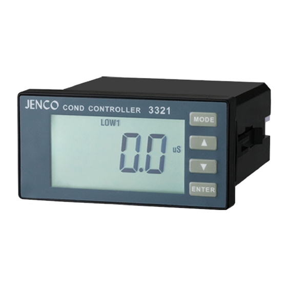
B. Front Panel The front panel consists of a 4-digit LCD display and 4 keys. 3321 COND CONTROLLER [ MODE ] key: 1a. In the Measure mode, this key will switch the display in sequence from Conductivity, Temperature and back to Conductivity again or from Resistivity, Temperature and back to Resistivity again. - Page 7 [ UP ] key: 2a. In the Calibration mode, pressing this key will increase the numeral increment. In the Setting mode, pressing this key will show the next possible option and increase the numeral increment. 2b. In the Measure mode, pressing this key and [ENTER] key at the same time, the unit will enter the Calibration mode.
-
Page 8: Lcd Screen
the user to the next setting. C. LCD screen HI2 LOW1 LOW2 Major LCD display. CAL – This icon will be displayed if the meter is in the Calibration/Setting mode. - Page 9 HI1 & LOW1 – These icons, when displayed, indicate relay action and relay number. HI2 & LOW2 –These icons, when displayed, indicate relay action and relay number. MΩ– Unit indicator. ℃ – Temperature and unit display. uS – Unit indicator. ATC –This icon will be displayed when a temperature probe is connected.
-
Page 10: Rear Connectors
Specify “L’ = “Live Lead” 100 to 230 VAC Volts and “N” = “Neutral Lead” Connect the AC line to the rear of the instrument. The model 3321 can be used with 100~240V AC at 50/60 HZ. Make sure the EARTH connector is connected to the earth lead of the AC power line. -
Page 11: Measure Mode
【 Note 】 : (1) Make sure that the power is unplugged before wiring your probes etc. (2) Make sure you connect the AC power cord to the correct AC terminals. Incorrect connection may damage the unit permanently. Measure mode Turning on the unit will always display the Measure mode. -
Page 12: Setting Mode
Temperature – Current temperature of the solution. 【 Note 】 : Pressing [MODE] key in the Measure mode will cycle the display between the two modes above. Setting mode Pressing [DOWN] key and [ENTER] key at the same time, the meter will enter into the Setting mode. - Page 13 Select the preferred temperature compensation mode, press [ENTER] key to save, and enter the next setting screen. Temperature Coefficient select: Temperature compensation select ENTER ENTER ENTER probe Basic cell constant select Pressing [UP] key or [DOWN] key in this screen will cycle the display between E2.00, E0.00 above.
- Page 14 Probe Basic cell constant select: Temperature coefficient select ENTER ENTER ENTER ENTER Range select Pressing [UP] key or [DOWN] key in this screen will cycle the display from C1.00, C0.10 to C0.01 basic cell constant above. Select the preferred basic cell constant, press [ENTER] key to save, and enter the next setting screen.
- Page 15 CF04/0.00~19.99MΩ(Basic cell K is C0.01) or CF01/0.00~19.99uS/cm, CF02/0.0~199.9uS/cm(Basic cell K is C0.10) or CF01/0.0~199.9uS/cm, CF02/0~1999uS/cm, CF03/0.00~19.99mS/cm (Basic cell K is C1.00) above. Select the preferred basic cell constant , press [ENTER] key to save, and enter the next setting screen. ENTER ENTER ENTER...
- Page 16 ENTER ENTER ENTER Relay 1 HI/LOW select ENTER ENTER ENTER ENTER Relay 1 HI/LOW select...
- Page 17 Relay 1 High / Low select: Range select ENTER LOW1 ENTER ENTER Relay 1 set point value Pressing [UP] key or [DOWN] key in this screen will cycle the display from HI、 LOW modes above. Select the preferred mode, press [ENTER] key to save, and enter the next setting screen.
- Page 18 Relay 1 set point value : Relay 1 HI/LOW select ENTER Pressing [UP] key or [DOWN] key in this screen to adjust the value, press [ENTER] key to save, and enter the next setting screen. ENTER Relay 1 Hysteresis value Relay 1 hysteresis value: Relay 1 set point select Pressing [UP] key or [DOWN] key in this screen to...
-
Page 19: Conductivity/Resistivity Calibration Mode
Same as “Relay 1 hysteresis value” G. Conductivity/Resistivity Calibration mode The model 3321 uses 1-point calibration for conductivity or resistivity. In the Measure mode, pressing [UP] key and [ENTER] key at the same time to allow the meter to go to the Conductivity / Resistivity calibration mode. -
Page 20: Controlling The Relays
standization solution value, then press [ENTER] key to save. Calibration is now completed. H. Controlling the relays Isolation voltage: The maximum isolation voltage of the relay output contacts is 1500 VDC. The voltage differential between the relay output contacts and the load should not exceed 1500 VDC. - Page 21 Relay action, relay set point and hysteresis value: Relay Action Effective RELAY-ON Set Point Effective RELAY-OFF Set Point S.P. + (1/2 H.V) S.P. – (1/2 H.V) S.P. – (1/2 H.V) S.P. + (1/2 H.V.) S.P. = Relay Set point H.V. = Hysteresis value (Dead Band) If the relay action is set to HIGH, the relay will turn ON at (Set Point +1/2 Hysteresis ), and will turn OFF at (Set Point -1/2 Hysteresis ).
-
Page 22: Error Display And Troubleshooting
ERVIEW ERROR DISPLAY AND TROUBLESHOOTING Conductivity/ Temperature Display Possible cause(s) Resistivity Display Mode [Action(s)] Display "OvEr" -10.0~120.0°C Measure Reading is over the specified mode range. [Change range to higher level] “Undr” -10.0~120.0°C Measure Reading is under user specified mode range. [Change range to lower level] [Immerse the conductivity probe into standization solution.]... - Page 23 lower temperature.] [Replace temperature probe.] b. No temperature sensor. [Adjust the manual temperature to -10~120°C.] "OvEr" “Undr” Measure a. Temperature < -10.0°C. mode [Bring standization solution higher temperature.] [Replace temperature probe.] b. No temperature sensor. [Adjust the manual temperature to -10~120°C.]...
-
Page 24: Specifications
SPECIFICATIONS Conductivity/Resistivity: Basic Cell K Range Resolution Accuracy 0.01 0.000~1.999uS/cm 0.001uS/cm ±0.5%FS ± 1 digit 0.00~19.99MΩ 0.01MΩ 0.01 0.00~19.99uS/cm 0.01uS/cm ±0.5%FS ± 1 digit 0.000~1.999MΩ 0.001MΩ 0.10 0.00~19.99uS/cm 0.01uS/cm ±0.5%FS ± 1 digit 0.10 0.0~199.9uS/cm 0.1uS/cm ±0.5%FS ± 1 digit 1.00 0.0~199.9uS/cm 0.1uS/cm... - Page 25 Conductivity/Resistivity: Cell Constant 0.01, 0.1, 1.0; 2 wire. Reference Temperature 25.0 °C, factory set. Temperature Coefficient 2.00 or 0.00%, user selectable. Temperature: Temperature sensor Thermistor: 10k ohm at 25 °C, (User selectable) Manual Controller: Control type Two ON/OFF control Relay output (Resistive load only) 5A at 115VAC or 2.5A at 220VAC General: Keys...
-
Page 26: Warranty
If you purchased the item from our Jenco distributors and it is under warranty, please contact them to notify us of the situation. Jenco Service Department alone will determine if the product problem is due to deviations or customer misuse. - Page 27 Jenco will not be responsible for damage resulting from careless or insufficient packing. A fee will be charged on all authorized returns. 【 Note 】 : Jenco reserves the right to make improvements in design, construction and appearance of our products without notice.
- Page 28 Shanghai Jenco Instruments, Ltd. 18 Wang Dong Zhong Road Sijing Town, Songjiang Shanghai, China TEL: 86-021-5761-9599 FAX: 86-021-5761-9598 E-Mail: sales@jenco.com.cn Website: www.jenco.com.cn...
Need help?
Do you have a question about the 3321 and is the answer not in the manual?
Questions and answers