Advertisement
88 5527 49
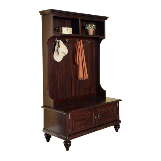
Hall Tree Stand
IMPORTANT NOTE
Carefully remove all the parts from the carton and put
them individually on a soft cloth to prevent scratches
or other damages occuring to the parts.
We have taken great care in the design of this
product and request that you carefully and strictly
follow our assembly instructions to ensure a
completed product as it was designed.
Part List
A.
Seat
1 pc.
E.
Back Stretcher
1 pc.
F.
Back Stretcher
2 pcs.
K.
Base
1 pc.
L.
Front Stretcher
1 pc.
M.
Top
1 pc.
Hardware List
Spring Support
2 pcs.
Tools required for assembly :
Home Styles Consumer Assistance: www.homestyles-furniture.com,
servicedesk@homestyles-furniture.com, 888-680-7460, 877-831-0319
B.
Side Panel
1 pc.
G.
Back Panel
1 pc.
N.
Side Panel
1 pc.
Hex Wrench
1 pc.
Wood Screw for
Small Hex Wrench
Spring
1 pc.
8 pcs. (+1 extra)
Phillips screwdriver
D.
C.
Front Panel
Side Panel
1 pc.
1 pc.
H.
Arm
1 pc.
O.
Side Panel
1 pc.
P.
Q.
Rail
Back Panel
1 pc.
2 pcs.
Cam Lock
Head Cap Bolt
24 pcs. (+6 extra)
15 pcs. (+1 extra)
Wood Screw for
Back Panel
24 pcs. (+1 extra)
Tools recommended for assembly :
I.
Arm
1 pc.
R.
Back Panel
1 pc.
S.
Back Stretcher
1 pc.
T.
Back Stretcher
1 pc.
Cam Lock Screw
24 pcs. (+2 extra)
Wood Screw
for Hook
8 pcs. (+1 extra)
J.
Leg
4 pcs.
Hook
4 pcs.
Level
Advertisement
Table of Contents

Subscribe to Our Youtube Channel
Related Manuals for Home Styles 88 5527 49


Summary of Contents for Home Styles 88 5527 49
- Page 1 Hook 1 pc. 2 pcs. 8 pcs. (+1 extra) 24 pcs. (+1 extra) 8 pcs. (+1 extra) 4 pcs. Phillips screwdriver Tools required for assembly : Tools recommended for assembly : Level Home Styles Consumer Assistance: www.homestyles-furniture.com, servicedesk@homestyles-furniture.com, 888-680-7460, 877-831-0319...
- Page 2 Assembly Instructions 2/6 IMPORTANT * Do not tighten up all the screws until each part is properly assembled. * You should keep Hex Wrench in a safe place as you may need to tighten up the Head Cap Bolts in the future. Head Cap Bolts STEP 1 Attach Legs (J) to Base (K)
- Page 3 Assembly Instructions 3/6 Cam Lock STEP 3 Attach Back Stretcher (E) and (F) to Side Panel (B) using Cam Locks. Slide Back Panel (G) into place. Attach Front Panel (D) to Side Panel (B) using Cam Locks. Attach Side Panel (C) to unit using Cam Locks. Cam Lock STEP 4 Attach Base (K) to unit using Cam Locks.
- Page 4 Assembly Instructions 4/6 Cam Lock STEP 5 Attach Front Stretcher (L) Back Stretcher (F) and (S) to Side Panel (N) using Cam Locks. Slide Back Panel (R) to unit. Attach Rail (P) to Back Stretcher (S) and slide Back Panels (Q) to unit. Attach Back Stretcher (T) to unit using Cam Lock.
- Page 5 Assembly Instructions 5/6 STEP 7 Place the top unit onto the base unit with Head Cap Bolts. Head Cap Bolt Head Cap Bolt STEP 8 Attach the Seat (A) to the base unit with Head Cap Bolts. Spring Support Wood Screw for Spring Support STEP 9...
- Page 6 Assembly Instructions 6/6 Hook Wood Screw Figure 2 for Hook Hook STEP 10 Attach Hooks to the top of unit with Wood Screws for Hooks. (see Figure 2) STEP 11 To level the unit, adjust the adjustable levelers on the bottom of legs. (See figure 3) Attach Wood Screws for Back Panel to the back of the unit.
Need help?
Do you have a question about the 88 5527 49 and is the answer not in the manual?
Questions and answers