Advertisement
Quick Links
Advertisement

Subscribe to Our Youtube Channel
Related Manuals for Workrite Ergonomics Sequoia SQ-633


Summary of Contents for Workrite Ergonomics Sequoia SQ-633
- Page 1 Workrite Sequoia Assembly Instructions for Model SQ-633 #1500209 - Rev A...
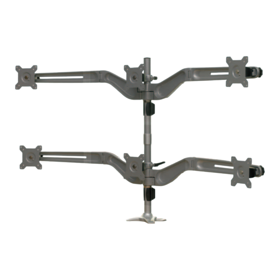
- Page 2 Parts grouped by carton Note: Part letters are nonsequential to accommodate all Sequoia Models Capped Pole carton, 3 monitors, includes Heavy Duty base: Capped Pole Center VESA Mount M8 × 50mm Arm Bolt Qty: 1 Qty: 1 Qty: 2 Cable Manager Steel Spacers Qty: 1 Qty: 2...
- Page 3 Extension Pole carton, 3 monitors: Extension Pole Center VESA Mount M8 × 50mm Arm Bolt Qty: 1 Qty: 1 Qty: 2 Steel Spacers Pole Coupler Qty: 2 Qty: 1 Outside VESA Mounts 8mm Flat Washer Qty: 2 Cable Manager Qty: 4 Qty: 1 6mm Hex Wrench Qty: 1...
- Page 4 2.5mm Hex Wrench (I) Install Cable Manager (B) onto the Pole and slide down to the bottom. Place Collar (C) onto the pole about 6” up from the bottom and install Set Screw (G) and tighten securely. Workrite Ergonomics 800.959.9675 www.workriteergo.com...
-
Page 5: Important Note
Screws (H) and tighten securely with a #2 Phillips screwdriver. Outer Monitor Mount: Align the outer mounts (K) to the VESA pattern in the monitors. Install 4 VESA Monitor Screws (H) and tighten securely with a #2 Phillips screwdriver. Workrite Ergonomics 800.959.9675 www.workriteergo.com... - Page 6 Place Steel Spacer (Q) on M8 × 5mm Arm Bolt (P) and attach Wing Bars to Wing Bar Mounts. Tighten Securely with 6mm Hex Wrench (S). Repeat this step for the remaining Wing Bar. Workrite Ergonomics 800.959.9675 www.workriteergo.com...
- Page 7 Note: During assembly it may become necessary to adjust the width of the outer monitors to adjust for curved alignment and minimize gaps between monitors. To do this simply loosen, move, and retighten the Mount Knob (F) to the wing bars. Workrite Ergonomics 800.959.9675 www.workriteergo.com...
- Page 8 Extension Pole (AA) and tighten securely. Install the Capped Pole (A) into the threads on the Pole Coupler and tighten securely. Insert 2 Set Screws (G) into the Coupler. Tighten securely with the 2.5mm Hex Wrench (I). Workrite Ergonomics 800.959.9675 www.workriteergo.com...
- Page 9 Place Steel Spacer (Q) on M8 × 5mm Arm Bolt (P) and attach Wing Bars to Wing Bar Mounts. Tighten Securely with 6mm Hex Wrench (S). Repeat this step for the remaining Wing Bar. Workrite Ergonomics 800.959.9675 www.workriteergo.com...
- Page 10 Note: During assembly it may become necessary to adjust the width of the outer monitors to adjust for curved alignment and minimize gaps between monitors. To do this simply loosen, move, and retighten the Mount Knob (F) to the wing bars. Workrite Ergonomics 800.959.9675 www.workriteergo.com...
- Page 11 Arc Adjustment +/- 10° Horizontal Adjustment Vertical Adjustment with with VESA Mount Knob Ratchet Lever & Collar Guide monitor and power cables over and around Ratchet Levers and Wing Knobs then through the Cable Manager (B). Workrite Ergonomics 800.959.9675 www.workriteergo.com...
Need help?
Do you have a question about the Sequoia SQ-633 and is the answer not in the manual?
Questions and answers