
Spectris PARTICLE MEASURING SYSTEMS MiniCapt Manuals
Manuals and User Guides for Spectris PARTICLE MEASURING SYSTEMS MiniCapt. We have 1 Spectris PARTICLE MEASURING SYSTEMS MiniCapt manual available for free PDF download: Operation Manual
Spectris PARTICLE MEASURING SYSTEMS MiniCapt Operation Manual (217 pages)
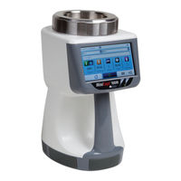
Mobile Microbial Air Sampler
Brand: Spectris
|
Category: Measuring Instruments
|
Size: 5 MB
Table of Contents
-
-
-
-
Connections23
-
Front23
-
Leds23
-
Touchscreen23
-
USB Port24
-
-
-
-
Installation36
-
-
-
Home Screen50
-
-
About Screen63
-
-
-
-
-
-
-
Alarm Comments105
-
-
-
-
-
-
Add a User144
-
Modify a User147
-
Remove a User148
-
User Management150
-
-
-
-
-
Cable Connectors176
-
-
Modbus Overview182
-
Input Registers183
-
-
-
-
Data Section186
-
-
Coils190
-
Table A-4 Coils191
-
-
-
Regulator200
-
Solenoid Valve200
-
Specifications201
-
-
Advertisement
Advertisement
Related Products
- Spectris PARTICLE MEASURING SYSTEM HSLIS e-Series
- Spectris PARTICLE MEASURING SYSTEMS AirSentry II
- Spectris Particle Measuring Systems LiQuilaz II E
- Spectris Particle Measuring Systems LiQuilaz II S
- Spectris PARTICLE MEASURING SYSTEMS Lasair Pro 310
- Spectris PARTICLE MEASURING SYSTEMS Lasair Pro 350
- Spectris PARTICLE MEASURING SYSTEMS Lasair Pro 5100
- Spectris 04416001A
- Spectris Bruel & Kjaer VCM-3
- Spectris Bruel & Kjaer VIBRO Condition Monitoring 3