
Related Manuals for Lantech IPGS-0005T-4


Summary of Contents for Lantech IPGS-0005T-4
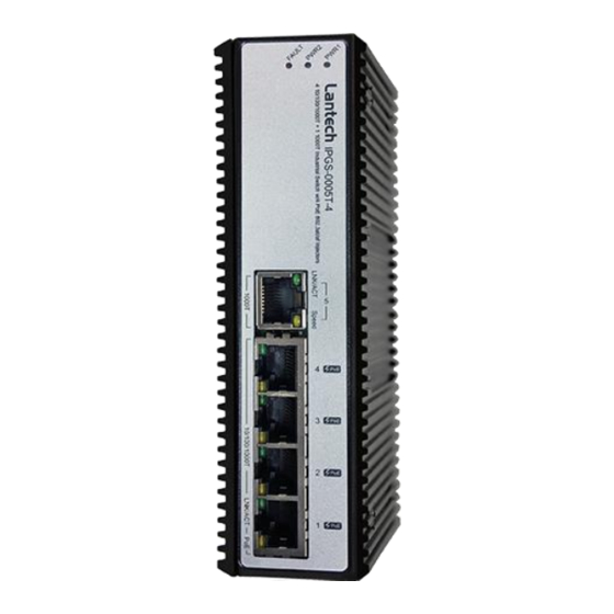
- Page 1 Lantech IPGS-0005T-4 4 10/100/1000T PoE at + 1 1000T Industrial Unmanaged Switch User Manual V1.00 Jan-2018...
-
Page 2: Table Of Contents
Content Overview ............1 Introduction ............. 1 Features / Model List ..........2 Packing List ............3 Safety Precaution ........... 3 Hardware Description ......... 4 Dimensions ............. 4 Wiring the Power Inputs .......... 5 Wiring the Fault Alarm Contact ....... 6 LED Indicators ............ - Page 3 Troubleshooting ..........17...
- Page 4 Recommendation for Shielded network cables STP cables have additional shielding material that is used to reduce external interference. The shield also reduces the emission at any point in the path of the cable. Our recommendation is to deploy an STP network cable in demanding electrical environments.
- Page 5 Lantech Communications Global Inc. Products offered may contain software which is proprietary to Lantech Communications Global Inc. The offer or supply of these products and services does not include or infer any transfer of ownership.
- Page 6 FCC Warning This Equipment has been tested and found to comply with the limits for a Class-A digital device, pursuant to Part 15 of the FCC rules. These limits are designed to provide reasonable protection against harmful interference in a residential installation. This equipment generates, uses, and can radiate radio frequency energy.
-
Page 7: Overview
Overview Introduction The unmanaged industrial switch is a cost-effective solution and meets the high reliability requirements demanded by industrial applications. High-Speed Transmissions The Industrial switch includes a switch controller that can automatically sense transmission speeds (10/100/1000 Mbps). The RJ-45 interface can also be auto-detected, so MDI or MDI-X is automatically selected and a crossover cable is not required. -
Page 8: Features / Model List
Features / Model List Store-and-Forward switching architecture 8K MAC address table Supports full/half duplex flow control IEEE 802.3at/af PoE+ standard (PoE models) Supports MDI/MDI-X auto-crossover Relay contact to connect with alarm system Provides flexible mounting: DIN-rail, Panel Mounting* Power Operating Model Name... -
Page 9: Packing List
Packing List 1 x Industrial Ethernet Switch (w/ terminal block and DIN-Rail kit) Caps for RJ45-port Safety Precaution Attention If DC voltage is supplied by an external circuit, please use a protection device on the power supply input. -
Page 10: Hardware Description
Hardware Description In this paragraph, we will introduce the Industrial switch’s dimensions, port, cabling information, and wiring installation. Dimensions 43 x 152 x 105 mm (W x H x D) -
Page 11: Wiring The Power Inputs
Wiring the Power Inputs Please follow the steps below to insert the power wires. V+ V1- V+ V- 1. Insert the positive and negative wires into the V+ and V- contacts on the terminal block connector. 2. Tighten the wire-clamp screws to prevent the DC wires from loosing. -
Page 12: Wiring The Fault Alarm Contact
Wiring the Fault Alarm Contact The fault alarm contacts are in the middle of the terminal block connector as the picture shows below. Inserting the wires, the switch will detect the fault status of the power failure, or port link failure (available for managed model) and then forms an open circuit. -
Page 13: Led Indicators
LED Indicators The LED indicators located on the front panel display the power status and network status of the Industrial switch; each has their own specific meaning as the table shown below. Color Description Power input 1 is active PWR1 Green Power input 1 is inactive PWR2... - Page 14 Power input 2 is inactive Power input 1 or 2 is inactive Fault Power input 1 and 2 are both functional, or no power inputs A network device is detected. LNK/ACT Green The port is transmitting or receiving packets from the Blinking TX device.
-
Page 15: Rj-45 Pin Assignments
RJ-45 Pin Assignments The UTP/STP ports will automatically sense for Fast Ethernet (10Base- T/100Base-TX) or Gigabit Ethernet (10Base-T/100Base-TX/1000Base-T) connection. Auto MDI/MDIX means that the switch can connect to another switch or workstation without changing straight through or crossover cabling. See the figures below for straight through and crossover cable schema. ... - Page 16 Straight Through Cable Schema Crossover Cable Schema 10/100/1000Base-T Pinouts The table below describes the gigabit Ethernet RJ-45 pinouts. Signal name Description BI_DA+ Bi-directional pair A+ BI_DA- Bi-directional pair A- BI_DB+ Bi-directional pair B+ BI_DC+ Bi-directional pair C+ BI_DC- Bi-directional pair C- BI_DB- Bi-directional pair B- BI_DD+...
-
Page 17: Cabling
schema. Straight Through Cable Schema Crossover Cable Schema Cabling Use unshielded twisted-pair (UTP) or shielded twisted-pair (STP) cable for RJ-45 connections: 100Ω Category 3, 4 or 5 cable for 10Mbps connections, 100Ω Category 5 cable for 100Mbps, or 100Ω Category 5e/above cable for 1000Mbps connections. -
Page 18: Mounting Installation
Mounting Installation DIN-Rail Mounting Assembling the DIN-Rail Clip The DIN-rail clip is screwed on the industrial switch when out of factory. If not, please refer to the following steps and figure to secure the DIN- rail clip on the switch. 1, Use the screws to screw on the DIN-rail clip on the industrial switch. - Page 19 Hanging the Industrial Switch Follow the steps below to hang the industrial switch on the DIN rail. 1, First, position the rear side of the switch directly in front of the DIN rail. Make sure the top of the clip hooks over the top of the DIN rail. 2, Push the unit downward.
-
Page 20: Wall-Mount Plate Mounting (Optional)
Wall-Mount Plate Mounting (Optional) Follow the steps below to mount the industrial switch with the wall mount plates included. 1. To remove the DIN-Rail clip from the industrial switch, unscrew the screws to remove the DIN-Rail clip. 2. Place the wall-mount plates on the rear panel of the industrial switch. 3. -
Page 21: Hardware Installation
Hardware Installation In this paragraph, we will describe how to install the Industrial Unmanaged Switch and the installation points for the attention. -
Page 22: Installation Steps
Installation Steps Unpacked the Industrial switch. Check the DIN-Rail is screwed on the Industrial switch. If the DIN-Rail is not screwed on the Industrial switch. Please refer to DIN-Rail Mounting section for DIN-Rail installation. If you want to wall mount the Industrial switch, then please refer to Wall-Mount Plate Mounting section for wall mount plate installation. - Page 23 Troubleshooting Verify that you are using the included or appropriate power cord/adapter. Don’t use the power adapter with DC output higher than the power rating of the device. Otherwise, the device will burn down. Select the proper UTP/STP cable to construct your network. Please check that you are using the right cable.
Need help?
Do you have a question about the IPGS-0005T-4 and is the answer not in the manual?
Questions and answers