
Texas Instruments TPS549D22EVM-784 Manuals
Manuals and User Guides for Texas Instruments TPS549D22EVM-784. We have 2 Texas Instruments TPS549D22EVM-784 manuals available for free PDF download: User Manual
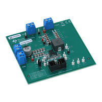
Texas Instruments TPS549D22EVM-784 User Manual (48 pages)
SWIFT Step-Down Converter Evaluation Module User's Guide
Brand: Texas Instruments
|
Category: Motherboard
|
Size: 2 MB
Table of Contents
Advertisement
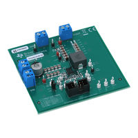
Texas Instruments TPS549D22EVM-784 User Manual (48 pages)
Single Synchronous Step-Down Converter With Full Differential Sense
Brand: Texas Instruments
|
Category: Motherboard
|
Size: 3 MB
Table of Contents
Advertisement
Related Products
- Texas Instruments TPS549D22
- Texas Instruments TPS549D22EVM
- Texas Instruments TPS54973EVM-017
- Texas Instruments TPS54972
- Texas Instruments TPS54380EVM-001
- Texas Instruments TPS54673EVM-225
- Texas Instruments TPS54231
- Texas Instruments TPS543620EVM
- Texas Instruments TPS546B24AEVM-2PH
- Texas Instruments SWIFT TPS54350EVM-235