Table of Contents
Advertisement
Quick Links
USER MANUAL
NI cRIO-9081
Reconfigurable Embedded Chassis with Integrated Intelligent Real-
Time Controller for CompactRIO
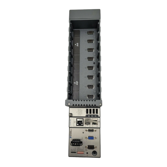
This document describes the features of the National Instruments cRIO-9081 and contains
information about mounting and operating the device.
RJ-45 Gigabit
Ethernet Port 1
RJ-45 Gigabit
Ethernet Port 2
USB 2.0
Host Port
USB 2.0
Host Port
USB 2.0
Host Port
USB 2.0
Host Port
cRIO-9081
Intel Celeron
U3405 1.06 GHz Dual-Core
Processor
+
+
Xilinx Spartan-6
LX75 FPGA
+
+
VGA Port
2 GB DDR3
16 GB
CFast SSD
RS-232
Serial Port
RJ-50
RS-485/422 (DTE)
Serial Port
MXI-Express Port
Hardware
Data
Advertisement
Table of Contents

Subscribe to Our Youtube Channel
Related Manuals for National Instruments cRIO-9081


Summary of Contents for National Instruments cRIO-9081
- Page 1 USER MANUAL NI cRIO-9081 Reconfigurable Embedded Chassis with Integrated Intelligent Real- Time Controller for CompactRIO This document describes the features of the National Instruments cRIO-9081 and contains information about mounting and operating the device. Intel Celeron VGA Port U3405 1.06 GHz Dual-Core...
- Page 2 NI-cRIO-9081-1856AAA. Finding the cRIO-9081 on the Network (Static IP) Complete the following steps to find the cRIO-9081 on the network if the host computer is using a static IP address. The following instructions are for host computers running Windows 7.
-
Page 3: Configuring Dip Switches
Click Properties. Record the IP address, Subnet mask, and Default gateway address. You need these settings to configure the network settings of the cRIO-9081 and to restore the network settings of the host computer. You can also access these settings by opening the Start menu,... - Page 4 Keep this switch in the OFF position during normal operation. If the switch is in the ON position at startup, the cRIO-9081 launches only the essential services required for updating its configuration and installing software. The LabVIEW Real-Time engine does not launch.
-
Page 5: Installing An Operating System
Restoring the Hard Drive to Factory Default Condition (Windows Only) You can restore the hard drive of the cRIO-9081 to factory default condition either from a recovery partition on the hard drive or from the NI Embedded Controller OEM Re-Installation DVD shipped with thecRIO-9081. -
Page 6: Rs-232 Serial Port
4. RJ-45 Ethernet Ports 1 and 2 RS-232 Serial Port The cRIO-9081 has an RS-232 serial port to which you can connect devices such as displays or input devices. Use the Serial VIs to read from and write to the serial port. Refer to the LabVIEW Help for information about the Serial VIs. - Page 7 RI/WAKE You can use the Ring Indicator (RI) on pin 9 to wake the controller from a low-power state. You can drive RI with a logic level high to wake the cRIO-9081. Refer to the specifications on ni.com/manuals for the RI wake voltage.
- Page 8 The following figure shows how to wire several NI FP-1001 banks in an RS-485/422 network controlled by the cRIO-9081. Only two FP-1001 banks are shown, but the cRIO-9081 can control up to 24 nodes. Install 120 Ω termination resistors at each end of the network.
-
Page 9: Usb Ports
778674-01 MXI Express Port You can use the MXI Express port on the cRIO-9081 to connect to a MXI Express chassis. Complete the following steps to connect one or more cRIO-9081 to a MXI Express device. Make sure the MXI Express device is configured and powered off. - Page 10 Caution Do not hot-swap USB devices while the cRIO-9081 is in a hazardous location or connected to high voltages. If the cRIO-9081 is not in a hazardous location, you can connect and disconnect USB devices without affecting operation. Video Port (VGA) The cRIO-9081 VGA port outputs graphics using VESA standard VGA analog signaling.
-
Page 11: Gigabit Ethernet Ports
RJ-45 Gigabit Ethernet Ports The cRIO-9081 has two tri-speed RJ-45 Gigabit Ethernet ports. By default, both Ethernet ports are enabled and configured to obtain an IP address automatically. The Ethernet ports can be configured in MAX. The following table shows the pinout for the RJ-45 Gigabit Ethernet ports. -
Page 12: Power Connector
If you apply power to both the V1 and V2 inputs, the cRIO-9081 operates from the V1 input. If the input voltage to V1 is insufficient, the cRIO-9081 operates from the V2 input. -
Page 13: Power Button
The FPGA continues to run unless you select the Autoload on Any Device Reset boot option. CMOS Reset Button The cRIO-9081 has a CMOS reset button that you can use to reset the CMOS and the BIOS. LEDs The cRIO-9081 provides the following LEDs. -
Page 14: Drive Led
The DRIVE LED is lit yellow when an internal drive is being accessed. STATUS LED Indicators The STATUS LED is off during normal operation. The cRIO-9081 indicates specific software error conditions by flashing the STATUS LED yellow a certain number of times every few seconds, as shown in the following table. - Page 15 If the problem persists, contact National Instruments. The cRIO-9081 indicates specific hardware error conditions by flashing the STATUS LED red a certain number of times every few seconds, as shown in the following table. Table 13. STATUS LED Hardware Indicators...
-
Page 16: Chassis Grounding Screw
The cRIO-9081 provides a chassis grounding screw. NI cRIO-9081 1. Chassis Grounding Screw For EMC compliance, you must connect the cRIO-9081 to earth ground through the chassis ground screw. Use wire that is 1.31 mm (16 AWG) solid copper wire with a maximum length of 1.5 m (5 ft). -
Page 17: Internal Real-Time Clock
CMOS BATTERY IS DEAD battery is dead. The cRIO-9081 still starts, but the system clock is reset to the date and time of the BIOS release. The battery is not user-replaceable. If you need to replace the CMOS battery, contact NI. - Page 18 You can also mount the cRIO-9081 in other orientations, on a nonmetallic surface, on a 35-mm DIN rail, on a desktop, or in a rack. Mounting the cRIO-9081 in these or other configurations can reduce the maximum allowable ambient temperature and can affect the typical accuracy of modules in the cRIO-9081.
-
Page 19: Mounting Requirements
Mounting Requirements Your installation must meet the following requirements for cooling and cabling clearance. Allow 50.8 mm (2.00 in.) on the top and the bottom of the cRIO-9081 for air circulation, as shown in the following figure. Figure 6. cRIO-9081 Cooling Dimensions... -
Page 20: Ambient Temperature
Ambient Temperature Measure the ambient temperature at each side of the cRIO-9081, 63.5 mm (2.50 in.) from the side and 50.8 mm (2.00 in.) forward from the rear of the cRIO-9081, as shown in the following figure. Figure 8. cRIO-9081 Ambient Temperature Location 50.8 mm... -
Page 21: Surface Mounting Dimensions
Fasten the cRIO-9081 to the surface using the M4 screws appropriate for the surface. Screws must not exceed 8 mm of insertion into the cRIO-9081. Tighten the screws to a maximum torque of 1.3 N · m (11.5 lb · in.). -
Page 22: Mounting The Device On A Panel
Mounting the Device on a Panel You can use the NI panel mounting kit to mount the cRIO-9081 on a panel. What to Use • cRIO-9081 • Screwdriver, Phillips #2 • NI panel mounting kit, 781919-01 – Panel mounting plate –... -
Page 23: Panel Mounting Dimensions
(7.43 in.) (4.29 in.) 58.2 mm (2.29 in.) Mounting the Device on a DIN Rail You can use the NI DIN rail mounting kit to mount the cRIO-9081 on a standard 35-mm DIN rail. What to Use • cRIO-9081 •... -
Page 24: Mounting The Device On A Desktop
Align the cRIO-9081 and the DIN rail clip. Fasten the DIN rail kit to the cRIO-9081 using the screwdriver and M4x10 screws. NI provides these screws with the DIN rail mounting kit. Tighten the screws to a maximum torque of 1.3 N · m (11.5 lb · in.). - Page 25 2. Adapter brackets (x2) 3. M4x10 screws (x6) What to Do Complete the following steps to mount the cRIO-9081 on a desktop. Use a #1 Phillips screwdriver and the six M4×10 screws to attach the adapter brackets to the chassis.
- Page 26 Figure 12. Attaching the Adapter Brackets to the cRIO-9081 Align one of the end brackets with the mounting hole at one of the ends of the chassis. 26 | ni.com | NI cRIO-9081 User Manual...
-
Page 27: Desktop Mounting Dimensions
Repeat steps 2 and 3 to attach the other end bracket to the other end of the chassis. Desktop Mounting Dimensions The following figures show the desktop mounting dimensions for the cRIO-9081. Figure 14. cRIO-9081 Desktop Mounting Front Dimensions 28.2 mm 28.1 mm... -
Page 28: Bios Configuration
BIOS Configuration Resetting the System CMOS and BIOS Settings The cRIO-9081 BIOS configuration information is stored in a nonvolatile memory location that does not require a battery to preserve the settings. Additionally, the BIOS optimizes boot time by saving specific system information to memory backed up by a battery (CMOS). - Page 29 Reset the DIP switches to their normal positions. Power-On Self Test Warning Messages The cRIO-9081 POST displays warning messages for specific issues onscreen. You can use MAX to enable Console Out to send these warning messages through the RS-232 serial port.
-
Page 30: Bios Setup Utility
This warning indicates that the BIOS settings have the default values. • Warning: Recovering from CPU Overtemp—This warning indicates that the thermal protection features of the cRIO-9081 shut down the system because of a high CPU temperature. • Warning: Recovering from Ambient Overtemp—This warning indicates that the thermal protection features of the cRIO-9081 shut down the system because of a high ambient temperature. -
Page 31: Main Setup Menu
The Advanced setup menu contains BIOS settings that do not require modification for normal operation of the cRIO-9081. If you have specific problems, such as unbootable disks or resource conflicts, you may need to examine the settings in this menu. -
Page 32: Sata Configuration Submenu
Hardware Prefetcher—This setting enables or disables CPU cache hardware prefetching. The default value is Enabled. • Adjacent Cache Line Prefetch—This setting enables or disables prefetching of adjacent cache lines from memory to the CPU cache. The default value is Enabled. 32 | ni.com | NI cRIO-9081 User Manual... -
Page 33: Video Configuration Submenu
DC power is lost. Valid values are Stay Off and Turn On. The default value is Turn On. When set to Stay Off, the cRIO-9081 returns to the soft off power state after AC power is restored. When set to Turn On, the cRIO-9081 powers on when DC power is restored. - Page 34 COM 2 (RS-485)—This setting enables or disables the onboard RS-485 serial port. The default value is Enabled. • Device Settings—This item displays the current base address and interrupt request level (IRQ) information for the onboard RS-485 serial port. 34 | ni.com | NI cRIO-9081 User Manual...
-
Page 35: Serial Port Console Redirection Submenu
LabVIEW RT, LabVIEW RT Safe Mode, or an installed OS such as Windows 7. The default is No. • Reset IP Address on Next Boot— This setting temporarily overrides the state of the IP RESET switch. The default is No. NI cRIO-9081 User Manual | © National Instruments | 35... -
Page 36: Labview Rt Configuration Overrides Submenu
1st Boot Device, followed by 2nd Boot Device and 3rd Boot Device. If multiple boot devices are not present, the BIOS setup utility does not display all of these configuration options. To select a boot device, 36 | ni.com | NI cRIO-9081 User Manual... -
Page 37: Boot Settings Configuration Submenu
Boot Option #1, Boot Option #2, Boot Option #3—These settings specify that the main Boot Option Priorities list displays the highest priority device. Optionally, each device can be disabled if the device is not used as a boot device. NI cRIO-9081 User Manual | © National Instruments | 37... -
Page 38: Security Menu
The Save & Exit setup menu includes the following settings: • Save Changes and Reset—This setup utility then exits and reboots the cRIO-9081. Any changes made to BIOS settings are stored in NVRAM. The <F10> key also selects this option. -
Page 39: Worldwide Support And Services
United States, visit the Worldwide Offices section of ni.com/ niglobal to access the branch office websites, which provide up-to-date contact information, support phone numbers, email addresses, and current events. NI cRIO-9081 User Manual | © National Instruments | 39... - Page 40 CONTAINED HEREIN AND SHALL NOT BE LIABLE FOR ANY ERRORS. U.S. Government Customers: The data contained in this manual was developed at private expense and is subject to the applicable limited rights and restricted data rights as set forth in FAR 52.227-14, DFAR 252.227-7014, and DFAR 252.227-7015. © 2016 National Instruments. All rights reserved. 375714A-03 Mar16...
Need help?
Do you have a question about the cRIO-9081 and is the answer not in the manual?
Questions and answers