
Subscribe to Our Youtube Channel
Related Manuals for National Instruments CompactRIO cRIO-FRC


Summary of Contents for National Instruments CompactRIO cRIO-FRC
- Page 1 Artisan Technology Group is your source for quality new and certified-used/pre-owned equipment SERVICE CENTER REPAIRS WE BUY USED EQUIPMENT • FAST SHIPPING AND DELIVERY Experienced engineers and technicians on staff Sell your excess, underutilized, and idle used equipment at our full-service, in-house repair center We also offer credit for buy-backs and trade-ins •...
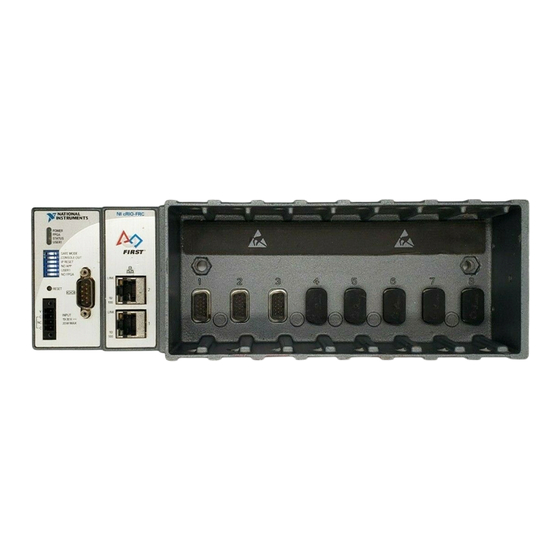
- Page 2 5 Power Connector 2 RS-232 Serial Port 6 Reset Button 3 RJ-45 Ethernet Port 2 7 DIP Switches 4 RJ-45 Ethernet Port 1 Figure 1. CompactRIO cRIO-FRC Artisan Technology Group - Quality Instrumentation ... Guaranteed | (888) 88-SOURCE | www.artisantg.com...
-
Page 3: Related Documentation
This document describes how to connect the cRIO-FRC to a network and how to use the features of the cRIO-FRC. This document also contains specifications for the cRIO-FRC. What You Need to Install the cRIO-FRC ❑ FIRST Robotics Competition kit, including cRIO-FRC reconfigurable embedded chassis with integrated intelligent real-time controller and the LabVIEW for FRC software ❑... - Page 4 87.3 mm (3.44 in.) 51.1 mm (2.04 in.) 3.1 mm (0.12 in.) Figure 3. cRIO-FRC, Front View with Dimensions © National Instruments Corporation cRIO-FRC Operating Instructions and Specifications Artisan Technology Group - Quality Instrumentation ... Guaranteed | (888) 88-SOURCE | www.artisantg.com...
- Page 5 Complete the following steps. Fasten the chassis to the panel mount kit using a number 2 Phillips screwdriver and two M4 × 16 screws. National Instruments provides these screws with the panel mount kit. You must use these screws because they are the correct depth and thread for the panel.
- Page 6 Caution Make sure that no I/O modules are in the chassis before removing it from the panel. © National Instruments Corporation cRIO-FRC Operating Instructions and Specifications Artisan Technology Group - Quality Instrumentation ... Guaranteed | (888) 88-SOURCE | www.artisantg.com...
-
Page 7: Mounting The Chassis On A Din Rail
DIN rail. Fasten the DIN rail clip to the chassis using a number 2 Phillips screwdriver and two M4 × 16 screws. National Instruments provides these screws with the DIN rail mount kit. Figure 7. Installing the DIN Rail Clip on the cRIO-FRC cRIO-FRC Operating Instructions and Specifications ni.com... - Page 8 Make sure that no I/O-side power is connected to the I/O module. The chassis power can be on when you install I/O modules. © National Instruments Corporation cRIO-FRC Operating Instructions and Specifications Artisan Technology Group - Quality Instrumentation ... Guaranteed | (888) 88-SOURCE | www.artisantg.com...
- Page 9 Align the I/O module with an I/O module slot in the chassis as shown in Figure 10. The module slots are labeled 1 to 8, left to right. 1 Insertion Groove 2 Latch Figure 10. Installing an I/O Module in the Chassis Squeeze the latches and insert the I/O module into the module slot.
- Page 10 Next you need to assign an IP address to the chassis. For information about assigning an IP address and setting up your network, refer to the FRC Control System Manual. © National Instruments Corporation cRIO-FRC Operating Instructions and Specifications Artisan Technology Group - Quality Instrumentation ... Guaranteed | (888) 88-SOURCE | www.artisantg.com...
-
Page 11: Wiring Power To The Chassis
Wiring Power to the Chassis The cRIO-FRC requires an external power supply that meets the specifications in the Power Requirements section. The cRIO-FRC filters and regulates the supplied power and provides power for all of the I/O modules. The cRIO-FRC has one layer of reverse-voltage protection. Complete the following steps to connect a power supply to the chassis. - Page 12 Pin 1 Pin 6 Pin 9 Pin 5 Figure 11. Controller Serial Port Table 2. DB-9 Pin Descriptions Signal © National Instruments Corporation cRIO-FRC Operating Instructions and Specifications Artisan Technology Group - Quality Instrumentation ... Guaranteed | (888) 88-SOURCE | www.artisantg.com...
-
Page 13: Configuring Dip Switches
Configuring DIP Switches Figure 12. DIP Switches All of the DIP switches are in the OFF position when the chassis is shipped from National Instruments. SAFE MODE Switch The position of the SAFE MODE switch determines whether the embedded LabVIEW Real-Time engine launches at startup. If the switch is in the OFF position, the LabVIEW Real-Time engine launches. -
Page 14: Ip Reset Switch
The NO APP switch does not affect C/C++ startup applications. You can use the Undeploy option in Wind River Workbench to disable a C/C++ application. © National Instruments Corporation cRIO-FRC Operating Instructions and Specifications Artisan Technology Group - Quality Instrumentation ... Guaranteed | (888) 88-SOURCE | www.artisantg.com... -
Page 15: Using The Reset Button
USER1 Switch You can define the USER1 switch for your application. Use the FRC ReadSwitch VI in your LabVIEW RT embedded VI to read the value of the USER1 switch. For more information about the FRC ReadSwitch VI, refer to the LabVIEW Help. NO FPGA Switch Push the NO FPGA switch to the ON position to prevent a LabVIEW FPGA application from loading at startup. -
Page 16: Status Led
Push the RESET button to cycle power to the chassis. The STATUS LED flashes once, indicating that the IP address is unconfigured. © National Instruments Corporation cRIO-FRC Operating Instructions and Specifications Artisan Technology Group - Quality Instrumentation ... Guaranteed | (888) 88-SOURCE | www.artisantg.com... -
Page 17: Specifications
Move the IP RESET switch to the OFF position. The network settings are restored. You can reconfigure the settings using the cRIO-FRC Imaging Utility from a computer on the same subnet. Note If the chassis is restored to the factory network settings, the LabVIEW Run-Time Engine does not load. - Page 18 MAINS voltage. MAINS is a hazardous live electrical supply system that powers equipment. This category is for measurements of voltages from © National Instruments Corporation cRIO-FRC Operating Instructions and Specifications Artisan Technology Group - Quality Instrumentation ... Guaranteed | (888) 88-SOURCE | www.artisantg.com...
-
Page 19: Safety Standards
specially protected secondary circuits. Such voltage measurements include signal levels, special equipment, limited-energy parts of equipment, circuits powered by regulated low-voltage sources, and electronics. Caution Do not connect the system to signals or use for measurements within Measurement Categories II, III, or IV. Safety Standards This product is designed to meet the requirements of the following standards of safety for electrical equipment for measurement, control,... -
Page 20: Environmental Management
Waste Electrical and Electronic Equipment (WEEE) At the end of their life cycle, all products must be sent to a WEEE recycling EU Customers center. For more information about WEEE recycling centers and National Instruments WEEE initiatives, visit ni.com/environment/weee.htm RoHS... -
Page 21: Shock And Vibration
Environmental The cRIO-FRC is intended for indoor use only, but it may be used outdoors if mounted in a suitably rated enclosure. Operating temperature (IEC 60068-2-1, IEC 60068-2-2) ...–20 to 55 °C Note To meet this operating temperature range, follow the guidelines in the installation instructions for your CompactRIO system. - Page 22 Connector 1 Connector 2 Pin 1 Pin 8 Pin 1 Pin 8 Figure 14. Ethernet Connector Pinout © National Instruments Corporation cRIO-FRC Operating Instructions and Specifications Artisan Technology Group - Quality Instrumentation ... Guaranteed | (888) 88-SOURCE | www.artisantg.com...
-
Page 23: Where To Go For Support
Phone support will not be available before or after the build period. If you would like to purchase additional parts or need to return a part to National Instruments at any time, please dial 1 866 511 6285. For limited telephone support outside the United States, contact your local... - Page 24 National Instruments, NI, ni.com, and LabVIEW are trademarks of National Instruments Corporation. Refer to the Terms of Use section on ni.com/legal for more information about National Instruments trademarks. Other product and company names mentioned herein are trademarks or trade names of their respective companies. For patents covering National Instruments products/technology, refer to the appropriate location: Help»Patents in your software, the patents.txt file on your...
- Page 25 Artisan Technology Group is your source for quality new and certified-used/pre-owned equipment SERVICE CENTER REPAIRS WE BUY USED EQUIPMENT • FAST SHIPPING AND DELIVERY Experienced engineers and technicians on staff Sell your excess, underutilized, and idle used equipment at our full-service, in-house repair center We also offer credit for buy-backs and trade-ins •...
Need help?
Do you have a question about the CompactRIO cRIO-FRC and is the answer not in the manual?
Questions and answers