Sign In
Upload
Manuals
Brands
IEI Technology Manuals
Motherboard
IMBA-H310
IEI Technology IMBA-H310 ATX Motherboard Manuals
Manuals and User Guides for IEI Technology IMBA-H310 ATX Motherboard. We have
2
IEI Technology IMBA-H310 ATX Motherboard manuals available for free PDF download: User Manual, Quick Installation Manual
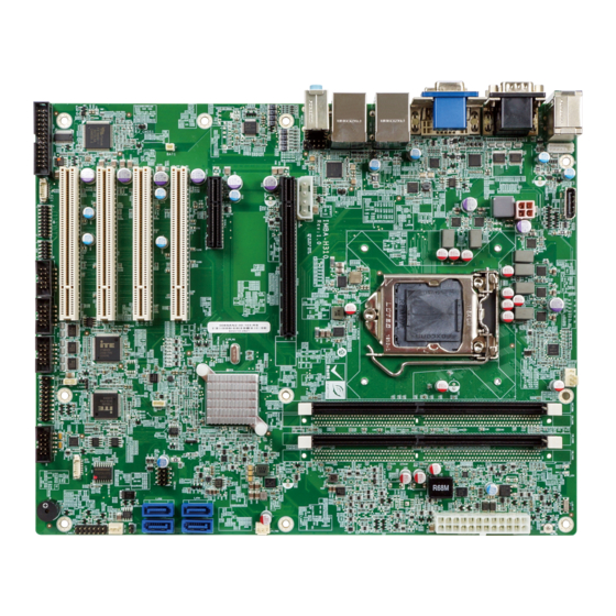
IEI Technology IMBA-H310 User Manual (135 pages)
Brand:
IEI Technology
| Category:
Motherboard
| Size: 5.22 MB
Table of Contents
Table of Contents
5
1 Introduction
15
Figure 1-1: IMBA-H310
16
Table 1-1: Model Variations
17
Figure 1-2: Connectors
18
Dimensions
19
Figure 1-3: Dimensions (MM)
19
Data Flow
20
Figure 1-4: Data Flow Diagram
20
Technical Specifications
21
Connectors
18
Ntroduction
16
Features
17
Model Variations
17
Table 1-2: IMBA-H310 Specifications
22
2 Packing List
23
Anti-Static Precautions
24
Unpacking Precautions
24
Packing List
25
Table 2-1: Packing List
25
Optional Items
26
Table 2-2: Optional Items
27
3 Connectors
28
Peripheral Interface Connectors
29
IMBA-H310 Layout
29
Peripheral Interface Connectors
30
Figure 3-1: Peripheral Interface Connectors
30
External Interface Panel Connectors
31
Table 3-1: Peripheral Interface Connectors
31
Figure 3-2: +12V Power Connector Pinout Location
32
Table 3-3: +12V Power Connector Pinouts
32
Figure 3-3: Additional Power Connector Location
33
Table 3-4: Additional Power Connector Pinouts
33
ATX Power Connector
34
Figure 3-4: ATX Power Connector Location
34
Table 3-5: ATX Power Connector Pinouts
34
Battery Connector
35
Figure 3-5: Battery Connector Location
35
Chassis Intrusion Connector
36
Table 3-2: Rear Panel Connectors
31
Additional Power Connector
33
Internal Peripheral Connectors
32
Power Connector
32
Figure 3-6: Chassis Intrusion Connector Location
36
Table 3-6: Battery Connector Pinouts
36
Table 3-7: Chassis Intrusion Connector Pinouts
36
Figure 3-9: EC Debug Connector Location
39
Figure 3-10: CPU Fan Connector Location
40
Table 3-10: CPU Fan Connector Pinouts
40
Fan Connectors (System)
41
Figure 3-7: DDR4 DIMM Slot Locations
37
Digital I/O Connector
38
Figure 3-8: Digital I/O Connector Location
38
Table 3-8: Digital I/O Connector Pinouts
38
Table 3-9: EC Debug Connector Pinouts
39
Fan Connector (CPU)
40
EC Debug Connector
39
DDR4 DIMM Slots
37
Table 3-12: System Fan Connector Pinouts (SYS_FAN2)
41
Table 3-13: Front Panel Audio Connector Pinouts
42
Table 3-14: Front Panel Connector Pinouts
43
Figure 3-14: I 2 C Connector Location
44
I 2 C Connector
44
Table 3-15: I 2 C Connector Pinouts
44
Figure 3-15: Internal Displayport Connector Location
45
Internal Displayport Connector
45
Table 3-16: Internal Displayport Connector Pinouts
45
Figure 3-16: Keyboard and Mouse Connector Location
46
Keyboard and Mouse Connector
46
Table 3-17: Keyboard and Mouse Connector Pinouts
46
Figure 3-17: LAN LED Connector Locations
47
LAN LED Connectors
47
Table 3-18: LAN LED Connector Pinouts
47
Figure 3-18: Parallel Port Connector Location
48
Parallel Port Connector
48
Table 3-19: Parallel Port Connector Pinouts
48
Figure 3-19: PCI Slot Locations
49
PCI Express X16 Slot
49
PCI Slots
49
Figure 3-20: Pcie X16 Slot Location
50
Figure 3-21: Pcie X4 Slot Location
50
PCI Express X4 Slot
50
Figure 3-22: Power Button Location
51
Power Button
51
Figure 3-23: RS-232 Serial Port Connector Locations
52
Serial Port Connector
52
Table 3-20: RS-232 Serial Port Connector Pinouts
52
Figure 3-24: RS-232/422/485 Connector Location
53
RS-232/422/485 Serial Port Connector
53
Figure 3-11: System Fan Connector Locations
41
Table 3-11: System Fan Connector Pinouts (SYS_FAN1)
41
Figure 3-13: Front Panel Connector Location
43
Front Panel Connector
43
Table 3-21: RS-232/422/485 Connector Pinouts
54
Table 3-22: DB-9 RS-232/422/485 Pinouts
54
Figure 3-30: USB 2.0 Connector Pinout Location
60
Figure 3-31: External Peripheral Interface Connectors
61
Figure 3-32: Audio Connector
61
Ethernet and USB 3.2 Gen 1 Connectors
62
Figure 3-33: LAN Connector
62
Table 3-29: USB 3.2 Gen 1 Port Pinouts
62
Table 3-30: LAN Pinouts
62
Keyboard/Mouse and USB 2.0 Connectors
63
Table 3-31: USB 2.0 Port Pinouts
63
Table 3-32: PS/2 Connector Pinouts
63
Serial Port Connectors
64
Table 3-33: Serial Port Connector Pinouts
64
VGA and DVI-D Connectors
65
Figure 3-25: SATA 6Gb/S Drive Connector Locations
55
SATA 6Gb/S Drive Connector
55
Table 3-23: SATA 6Gb/S Drive Connector Pinouts
55
Figure 3-26: Smbus Connector Location
56
Smbus Connector
56
Table 3-24: Smbus Connector Pinouts
56
Figure 3-27: SPI Flash Connector Location
57
SPI Flash Connector
57
Table 3-25: SPI Flash Connector Pinouts
57
Figure 3-28: SPI EC Flash Connector Location
58
SPI Flash Connector, EC
58
Table 3-26: SPI EC Flash Connector Pinouts
58
Figure 3-29: TPM Connector Pinout Location
59
Table 3-27: TPM Connector Pinouts
59
TPM Connector
59
Table 3-28: USB 2.0 Connector Pinouts
60
USB 2.0 Connector
60
Audio Connector
61
External Peripheral Interface Connector
61
Figure 3-12: Front Panel Audio Connector Location
42
Front Panel Audio Connector
42
Figure 3-34: Serial Port Connector Pinouts
64
Table 3-34: VGA Connector Pinouts
65
Figure 3-35: VGA Connector
65
Table 3-35: DVI-D Connector Pinouts
66
Figure 3-36: DVI-D Connector
66
4 Installation
67
Anti-Static Precautions
68
Installation Considerations
68
Figure 4-1: Disengage the CPU Socket Load Lever
70
Socket Lga1151 Cpu Installation
70
Figure 4-2: Remove Protective Cover
71
Figure 4-3: Insert the Socket LGA1151 CPU
72
Figure 4-4: Close the Socket LGA1151
72
Figure 4-5: Cooling Kit Support Bracket
74
Figure 4-6: DIMM Installation
75
AT/ATX Power Mode Setting
76
System Configuration
76
Table 4-1: AT/ATX Power Mode Switch Settings
76
Clear CMOS
77
DIMM Installation
75
Socket Lga1151 Cooling Kit Installation
73
Figure 4-7: AT/ATX Power Mode Switch Location
76
Table 4-2: Clear BIOS Jumper Settings
77
Figure 4-8: Clear CMOS Jumper Location
77
Figure 4-9: Flash Descriptor Security Override Jumper Location
78
Flash Descriptor Security Override
78
Table 4-3: Flash Descriptor Security Override Jumper Settings
78
Table 4-4: BIOS Options and Configured USB Ports
79
Table 4-5: USB Power Source Setup
79
Figure 4-10: SATA Drive Cable Connection
80
Figure 4-11: SATA Power Drive Connection
81
Driver Download
82
Driver Installation
82
USB Power Selection
79
Internal Peripheral Device Connections
80
SATA Drive Connection
80
Figure 4-12: IEI Resource Download Center
82
5 Bios
84
Introduction
85
Starting Setup
85
Using Setup
85
BIOS Menu Bar
86
Getting Help
86
Table 5-1: BIOS Navigation Keys
86
Unable to Reboot after Configuration Changes
86
Table 5-2: BIOS Options and Configured USB Ports
112
PCI Express Configuration
113
SATA Configuration
115
HD Audio Configuration
116
Security
117
Boot
118
Save & Exit
120
Main
87
Advanced
88
CPU Configuration
88
PCH-FW Configuration
91
PTT Configuration
92
Trusted Computing
93
ACPI Settings
94
RTC Wake Settings
95
F81866 Super IO Configuration
96
Serial Port 1 ~ 6 Configuration
97
Parallel Port Configuration
98
Iwdd H/W Monitor
99
Smart Fan Mode Configuration
100
Serial Port Console Redirection
101
USB Configuration
104
Chipset
105
System Agent (SA) Configuration
106
Memory Configuration
107
Graphics Configuration
108
PEG Port Configuration
110
PCH-IO Configuration
111
A Regulatory Compliance
121
B Product Disposal
123
CBIOS Options
125
D Watchdog Timer
128
E Error Beep Code
131
Pei Beep Codes
132
Dxe Beep Codes
132
F Hazardous Materials Disclosure
133
Rohs II Directive (2015/863/EU)
134
China Rohs
135
Advertisement
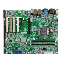
IEI Technology IMBA-H310 Quick Installation Manual (16 pages)
Brand:
IEI Technology
| Category:
Motherboard
| Size: 0.73 MB
Advertisement
Related Products
IEI Technology IMBA-H610
IEI Technology IMBA-H810
IEI Technology IMBA-H110
IEI Technology IMBA-H810-R10
IEI Technology IMBA-9454G
IEI Technology IMBA-Q670
IEI Technology IMBA-8650
IEI Technology IMBA-Q770
IEI Technology IMBA-G410
IEI Technology IMBA-8654
IEI Technology Categories
Motherboard
Touch Panel
Computer Hardware
Single board computers
Desktop
More IEI Technology Manuals
Login
Sign In
OR
Sign in with Facebook
Sign in with Google
Upload manual
Upload from disk
Upload from URL