IEI Technology IMBA-G412ISA User Manual
Atx motherboard for intel core 2 duo/quad cpu, 800/1066/1333 mhz fsb, ddr3, vga, lan, sata 3gb/s, pcie x16, pci, isa, usb, hd audio, rohs compliant
Hide thumbs
Also See for IMBA-G412ISA:
- User manual (164 pages) ,
- Quick installation manual (12 pages) ,
- User manual (164 pages)
Table of Contents
Advertisement
Quick Links
Advertisement
Table of Contents

Related Manuals for IEI Technology IMBA-G412ISA


Summary of Contents for IEI Technology IMBA-G412ISA
-
Page 1: User Manual
2010/10/262010/10/26 IMBA-G412ISA ATX Motherboard IEI Technology Corp. MODEL: IMBA-G412ISA ATX Motherboard for Intel® Core™2 Duo/Quad CPU, 800/1066/1333 MHz FSB, DDR3, VGA, LAN, SATA 3Gb/s, PCIe x16, PCI, ISA, USB, HD Audio, RoHS Compliant User Manual Page i Rev. 1.00 – 26 October, 2010... - Page 2 IMBA-G412ISA ATX Motherboard Revision Date Version Changes 26 October, 2010 1.00 Initial release Page ii...
- Page 3 2010/10/262010/10/26 IMBA-G412ISA ATX Motherboard Copyright COPYRIGHT NOTICE The information in this document is subject to change without prior notice in order to improve reliability, design and function and does not represent a commitment on the part of the manufacturer. In no event will the manufacturer be liable for direct, indirect, special, incidental, or consequential damages arising out of the use or inability to use the product or documentation, even if advised of the possibility of such damages.
-
Page 4: Table Of Contents
IMBA-G412ISA ATX Motherboard Table of Contents 1 INTRODUCTION......................0 H 0 H 0 H 3 2 8 H 3 2 8 H 3 2 8 H 1 .1 I ......................NTRODUCTION 1 H 1 H 1 H 3 2 9 H 3 2 9 H 3 2 9 H 1 .2 B... - Page 5 2010/10/262010/10/26 IMBA-G412ISA ATX Motherboard 3 .2.11 Power Connector.................... 2 9 H 2 9 H 2 9 H 3 5 7 H 3 5 7 H 3 5 7 H 3 .2.12 RS-232 Serial Port Connectors..............3 0 H 3 0 H 3 0 H 3 5 8 H 3 5 8 H 3 5 8 H 3 .2.13 RS-232/422/485 Serial Port Connector ............
- Page 6 IMBA-G412ISA ATX Motherboard 4 .6 E ........... XTERNAL ERIPHERAL NTERFACE ONNECTION 6 3 H 6 3 H 6 3 H 3 9 1 H 3 9 1 H 3 9 1 H 4 .6.1 Audio Connector ....................6 4 H 6 4 H 6 4 H 3 9 2 H 3 9 2 H 3 9 2 H 4 .6.2 PS/2 Keyboard and Mouse Connection ............
- Page 7 2010/10/262010/10/26 IMBA-G412ISA ATX Motherboard 5 .9.2 HDD Security....................9 7 H 9 7 H 9 7 H 4 2 5 H 4 2 5 H 4 2 5 H A BIOS OPTIONS ......................1 01 9 8 H 9 8 H 9 8 H 4 2 6 H 4 2 6 H 4 2 6 H B TERMINOLOGY......................
-
Page 8: List Of Figures
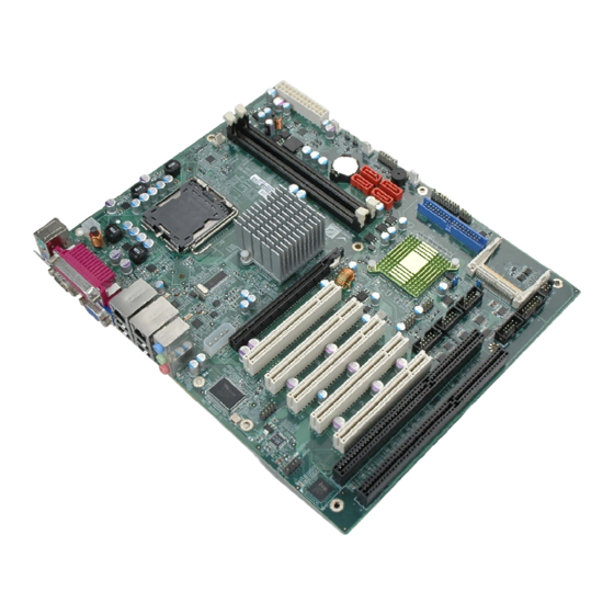
IMBA-G412ISA ATX Motherboard List of Figures F igure 1-1: IMBA-G412ISA ......................1 2 6 H 1 2 6 H 1 2 6 H 4 5 4 H 4 5 4 H 4 5 4 H F igure 1-2: Connectors ........................ - Page 9 1 5 9 H 1 5 9 H 1 5 9 H 4 8 7 H 4 8 7 H 4 8 7 H F igure 4-6: Securing the Heat sink to the IMBA-G412ISA ............1 6 0 H 1 6 0 H 1 6 0 H 4 8 8 H 4 8 8 H 4 8 8 H F igure 4-7: DIMM Installation.......................
- Page 10 IMBA-G412ISA ATX Motherboard F igure C-14: Select a Local Source Drive ................1 21 1 9 1 H 1 9 1 H 1 9 1 H 5 1 9 H 5 1 9 H 5 1 9 H F igure C-15: Select a Source Partition from Basic Drive ............
- Page 11 2010/10/262010/10/26 IMBA-G412ISA ATX Motherboard List of Tables T able 1-1: Technical Specifications....................2 1 1 H 2 1 1 H 2 1 1 H 5 3 9 H 5 3 9 H 5 3 9 H T able 2-1: Packing List.........................
- Page 12 IMBA-G412ISA ATX Motherboard T able 4-3: Clear BIOS Jumper Settings..................2 4 1 H 2 4 1 H 2 4 1 H 5 6 9 H 5 6 9 H 5 6 9 H T able 4-4: COM 2 Function Select Jumper Settings ..............
-
Page 13: Bios Menus
2010/10/262010/10/26 IMBA-G412ISA ATX Motherboard BIOS Menus M enu 1: Award BIOS CMOS Setup Utility .................. 2 4 7 H 2 4 7 H 2 4 7 H 5 7 5 H 5 7 5 H 5 7 5 H B IOS Menu 2: Standard BIOS Features.................. -
Page 14: Introduction
2010/10/262010/10/26 IMBA-G412ISA ATX Motherboard Chapter Introduction Page 1... -
Page 15: Benefits
The IMBA-G412ISA is an ATX motherboard with an 800/1066/1333 MHz front side bus. The LGA775 socket accepts Intel® Core™2 Duo/Quad processors and the motherboard supports two DDR3 DIMMs up to 4.0 GB each (8.0 GB total). The IMBA-G412ISA includes VGA output with up to QXGA resolution. Multiple expansion cards may be added, including PCIe x16, PCI and ISA interface. -
Page 16: Features
2010/10/262010/10/26 IMBA-G412ISA ATX Motherboard 1.3 Features Some of the IMBA-G412ISA motherboard features are listed below: ATX form factor RoHS compliant LGA775 CPU socket Supports two DDR3 DIMMs Supports dual display by VGA port and an optional PCIe x16 SDVO expansion card... -
Page 17: Connectors
410/26/2010158 IMBA-G412ISA ATX Motherboard 1.4 Connectors The connectors on the IMBA-G412ISA are shown in the figure below. Figure 1-2: Connectors Page 4... -
Page 18: Dimensions
2010/10/262010/10/26 IMBA-G412ISA ATX Motherboard 1.5 Dimensions The main dimensions of the IMBA-G412ISA are shown in the diagram below. Figure 1-3: Dimensions (mm) Page 5... -
Page 19: Data Flow
610/26/2010158 IMBA-G412ISA ATX Motherboard 1.6 Data Flow F igure 1-4 shows the data flow between the system chipset, the CPU and other 8 5 2 H 5 9 5 H 5 9 5 H 5 9 5 H components installed on the motherboard. -
Page 20: Technical Specifications
2010/10/262010/10/26 IMBA-G412ISA ATX Motherboard 1.7 Technical Specifications IMBA-G412ISA technical specifications are shown below. Specifications IMBA-G412ISA Form Factor Socket LGA775 Intel® Core™2 Duo/Quad, Pentium® D or CPU Supported Celeron® processor Front Side Bus (FSB) 800/1066/1333 MHz Northbridge Chipset Intel® G41 Memory Two 240-pin 800/1066 MHz dual-channel DDR3 SDRAM DIMMs (system max. - Page 21 810/26/2010158 IMBA-G412ISA ATX Motherboard I/O Interface One line-in Audio Jack One line-out One mic-in One 4-pin wafer for CPU fan Fan connector Three 3-pin wafer for system fans Two external PS/2 connectors Keyboard/Mouse Serial Ports Five RS-232 COM connectors One RS-232/422/485 COM connector USB 2.0/1.1 ports...
-
Page 22: Table 1-1: Technical Specifications
2010/10/262010/10/26 IMBA-G412ISA ATX Motherboard Physical Specifications 305 mm x 244 mm Dimensions Weight (Gross/Net) 1200 g / 750 g Table 1-1: Technical Specifications Page 9... -
Page 23: Packing List
1010/26/2010158 IMBA-G412ISA ATX Motherboard Chapter Packing List Page 10... -
Page 24: Anti-Static Precautions
Only handle the edges of the PCB: Don't touch the surface of the motherboard. Hold the motherboard by the edges when handling. 2.2 Unpacking Precautions When the IMBA-G412ISA is unpacked, please do the following: Follow the antistatic guidelines above. Make sure the packing box is facing upwards when opening. -
Page 25: Packing List
If any of the components listed in the checklist below are missing, do not proceed with the installation. Contact the IEI reseller or vendor the IMBA-G412ISA was purchased from or contact an IEI sales representative directly by sending an email to ales@iei.com.tw. -
Page 26: Optional Items
2010/10/262010/10/26 IMBA-G412ISA ATX Motherboard Quantity Item and Part Number Image Utility CD Quick Installation Guide Table 2-1: Packing List 2.4 Optional Items The following are optional components which may be separately purchased: Item and Part Number Image CPU cooler kit... -
Page 27: Table 2-2: Optional Items
1410/26/2010158 IMBA-G412ISA ATX Motherboard Item and Part Number Image ATA 66/100 flat cable (P/N: 32200-000052-RS) USB cable (P/N: CB-USB02-RS SATA power cable (P/N: 32102-000100-200-RS) DVI output SDVO card (P/N: SDVO-100DVI-R10) VGA output SDVO card (P/N: SDVO-100VGA-R10) Infineon TPM module (P/N: TPM-IN01-R11) -
Page 28: Connectors
2010/10/262010/10/26 IMBA-G412ISA ATX Motherboard Chapter Connectors Page 15... -
Page 29: Peripheral Interface Connectors
1610/26/2010158 IMBA-G412ISA ATX Motherboard 3.1 Peripheral Interface Connectors This chapter details all the jumpers and connectors. 3.1.1 Layout The figure below shows all the connectors and jumpers. Figure 3-1: Connectors and Jumpers Page 16... -
Page 30: Peripheral Interface Connectors
2010/10/262010/10/26 IMBA-G412ISA ATX Motherboard 3.1.2 Peripheral Interface Connectors The table below lists all the connectors on the board. Connector Type Label Audio connector 10-pin header FP_AUDIO1 Fan connector (CPU) 4-pin wafer CPU_FAN1 Fan connector (system) 3-pin wafer NB_FAN1, SYS_FAN1, SYS_FAN2 CompactFlash®... -
Page 31: External Interface Panel Connectors
USB port USB1, USB2 VGA connector 15-pin Female 3IN1_DSUB1C Table 3–2: External Peripheral Connectors 3.2 Internal Peripheral Connectors The section describes all of the connectors on the IMBA-G412ISA. 3.2.1 Audio Connector CN Label: FP_AUDIO1 CN Type: 10-pin header CN Location:... -
Page 32: Cpu Fan Connector
2010/10/262010/10/26 IMBA-G412ISA ATX Motherboard Figure 3-2: Audio Connector Location Description Description MIC_L Audio GND MIC_R FP_AUO_DETECT LINE_R F_SENSE LINE_L Table 3-3: Audio Connector Pinouts 3.2.2 CPU Fan Connector CN Label: CPU_FAN1 CN Type: 4-pin wafer F igure 3-3 CN Location:... -
Page 33: System Fan Connectors
2010/26/2010158 IMBA-G412ISA ATX Motherboard Figure 3-3: CPU Fan Connector Location Description +12 V Fan In Fan Control Table 3-4: CPU Fan Connector Pinouts 3.2.3 System Fan Connectors CN Label: NB_FAN1, SYS_FAN1 and SYS_FAN2 3-pin wafer CN Type: CN Location: F igure 3-4... -
Page 34: Cpu Power Input Connector
2010/10/262010/10/26 IMBA-G412ISA ATX Motherboard Description FANIN2 +12 V Table 3-5: System Fan Connector Pinouts (SYS_FAN1) Description +12 V Table 3-6: System Fan Connector Pinouts (SYS_FAN2 and SYS_FAN3) 3.2.4 CPU Power Input Connector CN Label: CPU12V1 CN Type: 4-pin connector CN Location:... -
Page 35: Digital I/O Connector
2210/26/2010158 IMBA-G412ISA ATX Motherboard 3.2.5 Digital I/O Connector CN Label: DIO1 10-pin header CN Type: CN Location: F igure 3-6 6 0 5 H 6 0 5 H 6 0 5 H CN Pinouts: T able 3-8 6 0 6 H 6 0 6 H 6 0 6 H The digital I/O connector provides programmable input and output for external devices. -
Page 36: Ide Connector
2010/10/262010/10/26 IMBA-G412ISA ATX Motherboard CN Location: F igure 3-7 6 0 7 H 6 0 7 H 6 0 7 H CN Pinouts: T able 3-9 6 0 8 H 6 0 8 H 6 0 8 H The front panel connector connects to the indicator LEDs and buttons on the computer's front panel. -
Page 37: Figure 3-8: Ide Connector Location
2410/26/2010158 IMBA-G412ISA ATX Motherboard The IDE connector can connect to an IDE hard drive or optical device. Figure 3-8: IDE Connector Location Description Description RESET# GROUND DATA 7 DATA 8 DATA 6 DATA 9 DATA 5 DATA 10 DATA 4... -
Page 38: Infrared Interface Connector
2010/10/262010/10/26 IMBA-G412ISA ATX Motherboard 3.2.8 Infrared Interface Connector CN Label: 5-pin header (1x5) CN Type: CN Location: F igure 3-9 6 1 1 H 6 1 1 H 6 1 1 H CN Pinouts: T able 3-11 6 1 2 H 6 1 2 H 6 1 2 H The infrared connector attaches to an infrared receiver for use with remote controls. -
Page 39: Pcie Power Input Connector
2610/26/2010158 IMBA-G412ISA ATX Motherboard The DIMM slots are for DDR3 DIMM memory modules. Figure 3-10: Memory Card Slot Location 3.2.10 PCIe Power Input Connector CN Label: PNC1 3-pin wafer (1x3) CN Type: CN Location: F igure 3-11 6 1 4 H 6 1 4 H 6 1 4 H... -
Page 40: Power Connector
2010/10/262010/10/26 IMBA-G412ISA ATX Motherboard Description VCC +5 V VCC +12 V Table 3-12: PCIe Power Input Connector Pinouts 3.2.11 Power Connector CN Label: PWR2 24-pin connector CN Type: CN Location: F igure 3-12 6 1 6 H 6 1 6 H 6 1 6 H... -
Page 41: Serial Port Connectors
2810/26/2010158 IMBA-G412ISA ATX Motherboard Description Description +12V +12V +3.3V Table 3-13: Power Connector Pinouts 3.2.12 RS-232 Serial Port Connectors CN Label: COM3, COM4, COM5, COM6 10-pin box header CN Type: CN Location: F igure 3-13 6 1 8 H 6 1 8 H 6 1 8 H... -
Page 42: Rs-232/422/485 Serial Port Connector
2010/10/262010/10/26 IMBA-G412ISA ATX Motherboard Description NCTS NDTR Table 3-14: Serial Port Connector Pinouts 3.2.13 RS-232/422/485 Serial Port Connector CN Label: COM2 CN Type: 14-pin box header CN Location: F igure 3-14 6 2 0 H 6 2 0 H 6 2 0 H... -
Page 43: Sata Drive Connectors
3010/26/2010158 IMBA-G412ISA ATX Motherboard Description Description Table 3-15: RS-232/422/485 Serial Port Connector Pinouts 3.2.14 SATA Drive Connectors CN Label: SATA1, SATA2, SATA3, SATA4 CN Type: 7-pin SATA drive connectors CN Location: F igure 3-15 6 2 2 H 6 2 2 H 6 2 2 H The SATA drive connectors can be connected to SATA 3Gb/s drives. -
Page 44: Spi Flash Connector
2010/10/262010/10/26 IMBA-G412ISA ATX Motherboard Figure 3-16: SMBus Connector Locations Description SMBDATA SMBCLK Table 3-16: SMBus Connector Pinouts 3.2.16 SPI Flash Connector CN Label: JSPI1 CN Type: 8-pin header CN Location: F igure 3-17 6 2 5 H 6 2 5 H 6 2 5 H... -
Page 45: Tpm Connector
3210/26/2010158 IMBA-G412ISA ATX Motherboard Figure 3-17: SPI Flash Connector Description Description +3.3V CLOCK Table 3-17: SPI Flash Connector 3.2.17 TPM Connector CN Label: TPM1 20-pin header (2x10) CN Type: CN Location: F igure 3-18 6 2 7 H 6 2 7 H 6 2 7 H... -
Page 46: Usb Connectors
2010/10/262010/10/26 IMBA-G412ISA ATX Motherboard Figure 3-18: TPM Connector Pinout Location Description Description TPMCLK LFRAME- PCIRST4- +5 V LAD3 LAD2 LAD0 LAD1 SMBCLK_MAIN SMBDATA_MAIN +3.3 V SERIRQ CLKRUN- +3.3 V LDRQ- Table 3-18: TPM Connector Pinouts 3.2.18 USB Connectors CN Label:... -
Page 47: External Peripheral Interface Connector Panel
3410/26/2010158 IMBA-G412ISA ATX Motherboard Figure 3-19: USB Connector Pinout Locations Description Description USBP4/6# USBP5/7 USBP4/6 USBP5/7# Table 3-19: USB Port Connector Pinouts 3.3 External Peripheral Interface Connector Panel The figure below shows the external peripheral interface connector (EPIC) panel. The... -
Page 48: Audio Connectors
2010/10/262010/10/26 IMBA-G412ISA ATX Motherboard 3.3.1 Audio Connectors CN Label: AUDIO1 Audio jacks CN Type: CN Location: F igure 3-20 6 3 1 H 6 3 1 H 6 3 1 H The audio jacks connect to external audio devices. Line In port (Light Blue): Connects a CD-ROM, DVD player, or other audio devices. -
Page 49: Lan Connectors
3610/26/2010158 IMBA-G412ISA ATX Motherboard Figure 3-22: PS/2 Pinout and Configuration Description Description KB_DATA MS_CLK KB_CLK KB_GND MS_DATA KB_GND Table 3-20: Keyboard Connector Pinouts 3.3.3 LAN Connectors CN Label: LAN1, LAN2 RJ-45 CN Type: CN Location: F igure 3-20 6 3 5 H 6 3 5 H 6 3 5 H... -
Page 50: Parallel Port Connector
2010/10/262010/10/26 IMBA-G412ISA ATX Motherboard Description Description LAN1/2_MDI0+ LAN1/2_MDI3- LAN1/2_MDI0- LAN1/2_MDI1+ LAN1/2_LINK100 LAN1/2_MDI1- LAN1/2_LINK1000 LAN1/2_MDI2+ LAN1/2_LED0 LAN1/2_MDI2- 3.3 V Table 3-21: LAN Pinouts 3.3.4 Parallel Port Connector CN Label: 3IN1_DSUB1A CN Type: DB-25 Female CN Location: F igure 3-20 6 3 7 H 6 3 7 H 6 3 7 H... -
Page 51: Serial Port Connector (Com1)
3810/26/2010158 IMBA-G412ISA ATX Motherboard Figure 3-23: Parallel Port Connector Location 3.3.5 Serial Port Connector (COM1) CN Label: 3IN1_DSUB1B (COM1) CN Type: DB-9 Male F igure 3-20 CN Location: 6 3 9 H 6 3 9 H 6 3 9 H... -
Page 52: Usb Connectors
2010/10/262010/10/26 IMBA-G412ISA ATX Motherboard 3.3.6 USB Connectors CN Label: USB1, USB2 USB port CN Type: CN Location: F igure 3-20 6 4 2 H 6 4 2 H 6 4 2 H CN Pinouts: T able 3-24 6 4 3 H 6 4 3 H 6 4 3 H The USB connector can be connected to a USB device. -
Page 53: Table 3-25: Vga Connector Pinouts
4010/26/2010158 IMBA-G412ISA ATX Motherboard Description Description GREEN BLUE CRT_PLUG# VGAVCC DDC DAT HSYNC VSYNC DDCCLK Table 3-25: VGA Connector Pinouts Page 40... -
Page 54: Installation
2010/10/262010/10/26 IMBA-G412ISA ATX Motherboard Chapter Installation Page 41... -
Page 55: Anti-Static Precautions
IMBA-G412ISA and severe injury to the user. Electrostatic discharge (ESD) can cause serious damage to electronic components, including the IMBA-G412ISA. Dry climates are especially susceptible to ESD. It is therefore critical that whenever the IMBA-G412ISA or any other electrical component is handled, the following anti-static precautions are strictly adhered to. - Page 56 This helps to prevent potential ESD damage. Turn all power to the IMBA-G412ISA off: When working with the IMBA-G412ISA, make sure that it is disconnected from all power supplies and that no electricity is being fed into the system.
-
Page 57: Basic Installation
4410/26/2010158 IMBA-G412ISA ATX Motherboard 4.3 Basic Installation This section outlines the parts that must be installed for the system to function correctly. 4.3.1 CPU Installation NOTE: To enable Hyper-Threading, the CPU and chipset must both support it. WARNING: CPUs are expensive and sensitive components. When installing the CPU please be careful not to damage it in anyway. -
Page 58: Figure 4-2: Remove Protective Cover
2010/10/262010/10/26 IMBA-G412ISA ATX Motherboard WARNING: DO NOT touch the pins at the bottom of the CPU. When handling the CPU, only hold it on the sides. Step 1: Remove the protective cover. The black protective cover can be removed by pulling up on the tab labeled "Remove". -
Page 59: Figure 4-4: Insert The Socket Lga775 Cpu
4610/26/2010158 IMBA-G412ISA ATX Motherboard Step 3: Inspect the CPU socket. Make sure there are no bent pins and make sure the socket contacts are free of foreign material. If any debris is found, remove it with compressed air. Step 4: Orientate the CPU properly. -
Page 60: Cooling Kit Installation
2010/10/262010/10/26 IMBA-G412ISA ATX Motherboard 4.3.2 Cooling Kit Installation WARNING: DO NOT use the original Intel® heat sink and fan. A proprietary one is recommended. Figure 4-5: Cooling Kits The cooling kit can be bought from IEI. The cooling kit has a heatsink and fan. -
Page 61: Figure 4-6: Securing The Heat Sink To The Imba-G412Isa
Step 6: Connect the fan cable. Connect the cooling kit fan cable to the fan connector on the IMBA-G412ISA. Carefully route the cable and avoid heat generating chips and fan blades. Step 0:... -
Page 62: Dimm Installation
Removing a DIMM. To remove a DIMM, push both handles outward. The memory module is ejected by a mechanism in the socket.Step 0: 4.3.4 Motherboard Installation To install the IMBA-G412ISA motherboard into the chassis please refer to the reference material that came with the chassis. Page 49... -
Page 63: Jumper Settings
OPEN a jumper means removing the plastic clip from a jumper. The IMBA-G412ISA includes some jumpers shown in T able 4-1. 6 5 6 H 6 5 6 H 6 5 6 H... -
Page 64: Clear Cmos Jumper
2010/10/262010/10/26 IMBA-G412ISA ATX Motherboard Jumper Location: F igure 4-8 6 5 8 H 6 5 8 H 6 5 8 H The AT Power Select jumper specifies the systems power mode as AT or ATX. Setting Description Open Use ATX power (Default) -
Page 65: Com 2 Function Select Jumper
5210/26/2010158 IMBA-G412ISA ATX Motherboard Figure 4-9: Clear BIOS Jumper Location 4.4.3 COM 2 Function Select Jumper Jumper Label: Jumper Type: 6-pin header Jumper Settings: T able 4-4 6 6 1 H 6 6 1 H 6 6 1 H F igure 4-10... -
Page 66: Compactflash® Setup
2010/10/262010/10/26 IMBA-G412ISA ATX Motherboard 4.4.4 CompactFlash® Setup Jumper Label: 2-pin header Jumper Type: T able 4-5 Jumper Settings: 6 6 4 H 6 6 4 H 6 6 4 H Jumper Location: F igure 4-11 6 6 5 H 6 6 5 H 6 6 5 H The CompactFlash®... -
Page 67: Usb Power Select Jumpers
5410/26/2010158 IMBA-G412ISA ATX Motherboard Setting Description Short 1-2 +5.0 V Short 2-3 +3.3 V Table 4-6: LCD Voltage Selection Jumper Settings Figure 4-12: LCD Voltage Selection Jumper Location 4.4.6 USB Power Select Jumpers Jumper Label: USBPW12, USBP34 Jumper Type: 3-pin header... -
Page 68: Internal Peripheral Device Connections
This section outlines the installation of peripheral devices to the onboard connectors. 4.5.1 SATA Drive Connection The IMBA-G412ISA is shipped with two SATA drive cables and one SATA drive power cable. To connect the SATA drives to the connectors, please follow the steps below. -
Page 69: Figure 4-14: Sata Drive Cable Connection
5610/26/2010158 IMBA-G412ISA ATX Motherboard Figure 4-14: SATA Drive Cable Connection Step 3: Connect the cable to the SATA disk. Connect the connector on the other end of the cable to the connector at the back of the SATA drive. See F igure 4-15. -
Page 70: Dual Rs-232 Cable With Slot Bracket
2010/10/262010/10/26 IMBA-G412ISA ATX Motherboard Figure 4-15: SATA Power Drive Connection 4.5.2 Dual RS-232 Cable with Slot Bracket The dual RS-232 cable slot connector consists of two connectors attached to two independent cables. Each cable is then attached to a D-sub 9 male connector that is mounted onto a slot. -
Page 71: External Peripheral Interface Connection
This section describes connecting devices to the external connectors on the IMBA-G412ISA. 4.6.1 Audio Connector The audio jacks on the external audio connector enable the IMBA-G412ISA to be connected to a stereo sound setup. To install the audio devices, follow the steps below. Step 1: Identify the audio plugs. -
Page 72: Ps/2 Keyboard And Mouse Connection
Step 0: 4.6.2 PS/2 Keyboard and Mouse Connection The IMBA-G412ISA has a dual PS/2 connector on the external peripheral interface panel. The dual PS/2 connector is used to connect to a keyboard and mouse to the system. Follow the steps below to connect a keyboard and mouse to the IMBA-G412ISA. -
Page 73: Lan Connection
Chapter 4. Step 2: Align the connectors. Align the RJ-45 connector on the LAN cable with one of the RJ-45 connectors on the IMBA-G412ISA. See F igure 4-19. 6 7 5 H 6 7 5 H 6 7 5 H... -
Page 74: Parallel Device Connection
RJ-45 connector into the on-board RJ-45 connector. Step 0: 4.6.4 Parallel Device Connection The IMBA-G412ISA has a single female DB-25 connector on the external peripheral interface panel for parallel devices. Follow the steps below to connect a parallel device to the IMBA-G412ISA. -
Page 75: Serial Device Connection
4.6.5 Serial Device Connection The IMBA-G412ISA has one male DB-9 connectors on the external peripheral interface panel for a serial device. Follow the steps below to connect a serial device to the IMBA-G412ISA. -
Page 76: Usb Device Connection
2010/10/262010/10/26 IMBA-G412ISA ATX Motherboard Figure 4-21: Serial Device Connector Step 3: Secure the connector. Secure the serial device connector to the external interface by tightening the two retention screws on either side of the connector. Step 0: 4.6.6 USB Device Connection The external USB Series "A"... -
Page 77: Vga Monitor Connection
Figure 4-22: USB Connector 4.6.7 VGA Monitor Connection The IMBA-G412ISA has a single female DB-15 connector on the external peripheral interface panel. The DB-15 connector is connected to a CRT or VGA monitor. To connect a monitor to the IMBA-G412ISA, please follow the instructions below. -
Page 78: Software Installation
Step 0: 4.7 Software Installation All the drivers for the IMBA-G412ISA are on the CD that came with the system. To install the drivers, please follow the steps below. Step 1: Insert the CD into a CD drive connected to the system. -
Page 79: Bios
6610/26/2010158 IMBA-G412ISA ATX Motherboard Chapter BIOS Page 66... -
Page 80: Introduction
2010/10/262010/10/26 IMBA-G412ISA ATX Motherboard 5.1 Introduction The BIOS is programmed onto the BIOS chip. The BIOS setup program allows changes to certain system settings. This chapter outlines the options that can be changed. 5.1.1 Starting Setup The UEFI BIOS is activated when the computer is turned on. The setup program can be activated in one of two ways. -
Page 81: Getting Help
6810/26/2010158 IMBA-G412ISA ATX Motherboard General help, only for Status Page Setup Menu and Option Page Setup Menu Load optimized defaults Save changes and Exit BIOS Table 5-1: BIOS Navigation Keys 5.1.3 Getting Help When F1 is pressed a small help window describing the appropriate keys to use and the possible selections for the highlighted item appears. - Page 82 2010/10/262010/10/26 IMBA-G412ISA ATX Motherboard BYOSOFT BIOS Setup Utility > Standard BIOS Features > BIOS Security Features > Advanced BIOS Features Load Optimized Defaults > Advanced Chipset Features Load Custom Defaults > Boot Configuration Features Save Custom Defaults > Power Management Features Save &...
-
Page 83: Standard Bios Features
7010/26/2010158 IMBA-G412ISA ATX Motherboard The following user configurable options are also available in B IOS Menu 1: 6 8 3 H 6 8 3 H 6 8 3 H Load Optimized Defaults Use the Load Optimized Defaults option to load optimal default values for each BIOS parameter in the setup menus. -
Page 84: System Information
2010/10/262010/10/26 IMBA-G412ISA ATX Motherboard BYOSOFT BIOS Setup Utility Standard BIOS Features System Date [02/12/2003] Item Help System Time [12:21:40] > System Information Year: 1900-2009, Press enter number adjust it. ↑ ↓=Move Highlight <Enter>=Select Entry F10=Save Esc=Exit Without Save F1=Scroll Help F9=Reset to Defaults... -
Page 85: Advanced Bios Features
7210/26/2010158 IMBA-G412ISA ATX Motherboard BYOSOFT BIOS Setup Utility Standard BIOS Features BIOS Version SA28BR10 Item Help Build Time 09/20/2010 16:08 ___________________ Processor Type Intel(R) Core(TM)2 Duo CPU E7500 @ 2.93GHz Processor Speed 2.93 GHz System Bus Speed 1064 MHz Microcode Revision... -
Page 86: Sata Configuration
2010/10/262010/10/26 IMBA-G412ISA ATX Motherboard 5.3.1 SATA Configuration Use the SATA Configuration menu ( B IOS Menu 5) to configure the IDE and SATA 6 8 7 H 6 8 7 H 6 8 7 H device configuration options. BYOSOFT BIOS Setup Utility... -
Page 87: Bios Menu 6: Onboard Devices Configuration
7410/26/2010158 IMBA-G412ISA ATX Motherboard BYOSOFT BIOS Setup Utility Advanced BIOS Features Onboard USB Controller <Enable> Item Help USB 2.0 Controller <Enable> ___________________ USB Keyboard Support <Enable> Enable USB Mouse Support <Enable> Disable Onboard Audio <Enable> Onboard LAN <Enable> Lan Boot ROM <Disable>... - Page 88 2010/10/262010/10/26 IMBA-G412ISA ATX Motherboard USB Keyboard Support [Enable] Use the USB Keyboard Support option to enable or disable the use of a USB keyboard. USB keyboard can be used Enable EFAULT Disable USB keyboard cannot be used USB Mouse Support [Enable] Use the USB Mouse Support option to enable or disable the use of a USB keyboard.
- Page 89 7610/26/2010158 IMBA-G412ISA ATX Motherboard Super IO Watchdog Control [Disable] Use the Super IO Watchdog Control option to enable or disable the watchdog function. If the watchdog is enabled, the default setting is 50 seconds. The minimum value is 50 seconds, while the maximum value is 255 seconds.
- Page 90 2010/10/262010/10/26 IMBA-G412ISA ATX Motherboard IRQ3 Serial port 1 IRQ address is 3 Serial port 1 IRQ address is 4 IRQ4 EFAULT IRQ10 Serial port 1 IRQ address is 10 IRQ11 Serial port 1 IRQ address is 11 Serial Port2 Address [2F8]...
- Page 91 7810/26/2010158 IMBA-G412ISA ATX Motherboard Serial port 3 I/O port address is 2F8 Serial port 3 I/O port address is 3E8 EFAULT Serial port 3 I/O port address is 2E8 Serial port 3 I/O port address is 2D0 Serial port 3 I/O port address is 2D8 Serial Port3 IRQ [IRQ11] Use the Serial Port3 IRQ option to select the interrupt address for serial port 3.
- Page 92 2010/10/262010/10/26 IMBA-G412ISA ATX Motherboard IRQ4 Serial port 4 IRQ address is 4 Serial port 4 IRQ address is 10 IRQ10 IRQ11 Serial port 4 IRQ address is 11 EFAULT Serial Port5 Address [2D0] Use the Serial Port5 Address option to select the base addresses for serial port 5...
- Page 93 8010/26/2010158 IMBA-G412ISA ATX Motherboard Serial port 6 I/O port address is 3E8 Serial port 6 I/O port address is 2E8 Serial port 6 I/O port address is 2D0 Serial port 6 I/O port address is 2D8 EFAULT Serial Port6 IRQ [IRQ11] Use the Serial Port6 IRQ option to select the interrupt address for serial port 6.
-
Page 94: Console Redirection Configuration
2010/10/262010/10/26 IMBA-G412ISA ATX Motherboard The parallel port operates in the enhanced parallel port mode (EPP). The EPP mode supports bi-directional communication between the system and the parallel port device and the transmission rates between the two are much faster than the Normal mode. -
Page 95: Bios Menu 7: Console Redirection Configuration
8210/26/2010158 IMBA-G412ISA ATX Motherboard BYOSOFT BIOS Setup Utility Advanced BIOS Features Console Redirection <Disable> Item Help ___________________ Configure Console Redirection ↑ ↓=Move Highlight <Enter>=Select Entry F10=Save Esc=Exit Without Save F1=Scroll Help F9=Reset to Defaults BIOS Menu 7: Console Redirection Configuration... -
Page 96: Advanced Chipset Features
2010/10/262010/10/26 IMBA-G412ISA ATX Motherboard COM3 System is remotely accessed through COM3 System is remotely accessed through COM4 COM4 COM5 System is remotely accessed through COM5 COM6 System is remotely accessed through COM6 Serial Port Baudrate [115200] Use the Serial Port Baudrate option to select baud rate through which the console redirection is made. -
Page 97: Bios Menu 8: Advanced Chipset Features
8410/26/2010158 IMBA-G412ISA ATX Motherboard BYOSOFT BIOS Setup Utility Advanced Chipset Features Memory Hole <Disable> Item Help Pre Allocated Memory <32M> ___________________ DVMT Mode <DVMT> Memory Hole DVMT Memory Size <256M> Boot Display Output Device <VBIOS> Panel Type <BY HARDWARE> ↑ ↓=Move Highlight <Enter>=Select Entry F10=Save... - Page 98 2010/10/262010/10/26 IMBA-G412ISA ATX Motherboard Use the DVMT Mode option to select the Intel Dynamic Video Memory Technology (DVMT) operating mode. DVMT Graphics memory dynamically allocated EFAULT according to the system and graphics needs. DVMT Memory Size [256M] Use the DVMT Memory Size option to specify the maximum amount of memory that can be allocated as DVMT 4.0 graphics memory.
-
Page 99: Boot Configuration Features
8610/26/2010158 IMBA-G412ISA ATX Motherboard 5.5 Boot Configuration Features Use the Boot Configuration Features menu ( B IOS Menu 9) to configure system boot 6 9 1 H 6 9 1 H 6 9 1 H options. BYOSOFT BIOS Setup Utility Boot Configuration Features >... -
Page 100: Boot Settings Configuration
2010/10/262010/10/26 IMBA-G412ISA ATX Motherboard 5.5.1 Boot Settings Configuration Use the Boot Settings Configuration menu ( B IOS Menu 10) to configure advanced 6 9 2 H 6 9 2 H 6 9 2 H system boot options. BYOSOFT BIOS Setup Utility... - Page 101 8810/26/2010158 IMBA-G412ISA ATX Motherboard Bootup Num-Lock [On] Use the Bootup Num-Lock BIOS option to specify if the number lock setting must be modified during boot up. Allows the Number Lock on the keyboard to be enabled EFAULT automatically when the computer system boots up. This allows the immediate use of the 10-key numeric keypad located on the right side of the keyboard.
-
Page 102: Boot Device Priority
2010/10/262010/10/26 IMBA-G412ISA ATX Motherboard 5.5.2 Boot Device Priority Use the Boot Device Priority menu ( B IOS Menu 11) to specify the boot sequence from 6 9 3 H 6 9 3 H 6 9 3 H the available devices. The drive sequence also depends on the boot sequence in the individual device section. -
Page 103: Subdevice Boot Configuration
9010/26/2010158 IMBA-G412ISA ATX Motherboard 5.5.3 SubDevice Boot Configuration Use the SubDevice Boot Configuration menu to specify the boot sequence of the available HDDs, removable devices, CD-ROM and BEC devices. BYOSOFT BIOS Setup Utility Boot Configuration Features > Hard Disk Priority... -
Page 104: Bios Menu 13: Power Management Features
2010/10/262010/10/26 IMBA-G412ISA ATX Motherboard BYOSOFT BIOS Setup Utility Power Management Features Power Supply Mode <BY HARDWARE> Item Help Power Supply Status [ATX POWER] ___________________ ACPI Suspend Type <S3> This option decides Restore On AC Power loss <Power off> whether the system >... -
Page 105: Apm Configuration
9210/26/2010158 IMBA-G412ISA ATX Motherboard Restore on AC Power Loss [Power Off] Use the Restore on AC Power Loss BIOS option to specify what state the system returns to if there is a sudden loss of power to the system. Power On... - Page 106 2010/10/262010/10/26 IMBA-G412ISA ATX Motherboard Disable Wake event not generated by PCI PME controller activity Resume By PCIE-PME [Enable] Use the Resume By PCI-PME BIOS option to enable activity on the PCI PME (power management event) controller to rouse the system from a suspend or standby state.
-
Page 107: Pnp/Pci Configurations
9410/26/2010158 IMBA-G412ISA ATX Motherboard Disable The real time clock (RTC) cannot generate a wake EFAULT event 5.7 PnP/PCI Configurations Use the PnP/PCI Configurations menu ( B IOS Menu 15) to set the plug and play, and 6 9 6 H 6 9 6 H 6 9 6 H PCI options. - Page 108 2010/10/262010/10/26 IMBA-G412ISA ATX Motherboard DM Channel 0 DM Channel 1 DM Channel 3 DM Channel 5 DM Channel 6 DM Channel 7 IRQ# Use the IRQ# address to specify what IRQs can be assigned to a particular peripheral device. Available...
-
Page 109: Pc Health Status
9610/26/2010158 IMBA-G412ISA ATX Motherboard D4000: 64K D8000: 16K D8000: 32K DC000: 16K 5.8 PC Health Status Use the PC Health Status menu ( B IOS Menu 16) to enable or disable the smart fan. 6 9 7 H 6 9 7 H 6 9 7 H... -
Page 110: Bios Menu 17: Pc Health Status
2010/10/262010/10/26 IMBA-G412ISA ATX Motherboard BYOSOFT BIOS Setup Utility PC Health Status CPU Core 1.264 V Item Help DRAM Voltage 1.544 V ___________________ +3.3V 3.376 V +12V 11.792 V 5.104 V +3.3VSB 3.424 V VBAT 3.312 V CPU Temperature 61ºC System Temperature 34ºC... -
Page 111: Bios Security Features
9810/26/2010158 IMBA-G412ISA ATX Motherboard Fan Speeds The following fan speeds are monitored: CPU Fan Speed System Fan Speed 5.9 BIOS Security Features Use the BIOS Security Features menu ( B IOS Menu 18) to set system and user 6 9 9 H 6 9 9 H 6 9 9 H passwords. -
Page 112: System Configuration Lock
2010/10/262010/10/26 IMBA-G412ISA ATX Motherboard Admin Password Use the Admin Password to set or change a administrator password. There is no password by default. If a administrator password must be installed, select this field and enter the password. After the password has been added, the option is changed to Unlock Password. -
Page 113: Bios Menu 20: Hdd Security
10010/26/2010158 IMBA-G412ISA ATX Motherboard BYOSOFT BIOS Setup Utility BIOS Security Features HDD PASSWORD CONFIGURATION: Item Help Security Supported ___________________ Security Enabled This allows to set Hard Disk passwords, Set HDD Password password length 6-15 ↑ ↓=Move Highlight <Enter>=Select Entry F10=Save... -
Page 114: Bios Options
2010/10/262010/10/26 IMBA-G412ISA ATX Motherboard Appendix BIOS Options Page 101... - Page 115 10210/26/2010158 IMBA-G412ISA ATX Motherboard Below is a list of BIOS configuration options in the BIOS chapter. Load Optimized Defaults..................... 2 6 8 H 2 6 8 H 2 6 8 H 7 0 2 H 7 0 2 H 7 0 2 H ...
- Page 116 2010/10/262010/10/26 IMBA-G412ISA ATX Motherboard Serial Port Baudrate [115200] ..................... 3 0 1 H 3 0 1 H 3 0 1 H 7 3 5 H 7 3 5 H 7 3 5 H Memory Hole [Disable] ......................3 0 2 H 3 0 2 H 3 0 2 H 7 3 6 H 7 3 6 H 7 3 6 H ...
- Page 117 10410/26/2010158 IMBA-G412ISA ATX Motherboard Appendix Terminology Page 104...
- Page 118 2010/10/262010/10/26 IMBA-G412ISA ATX Motherboard AC ’97 Audio Codec 97 (AC’97) refers to a codec standard developed by Intel® in 1997. ACPI Advanced Configuration and Power Interface (ACPI) is an OS-directed configuration, power management, and thermal management interface. AHCI Advanced Host Controller Interface (AHCI) is a SATA Host controller register-level interface.
- Page 119 10610/26/2010158 IMBA-G412ISA ATX Motherboard DIMM Dual Inline Memory Modules are a type of RAM that offer a 64-bit data bus and have separate electrical contacts on each side of the module. The digital inputs and digital outputs are general control signals that control the on/off circuit of external devices or TTL devices.
- Page 120 2010/10/262010/10/26 IMBA-G412ISA ATX Motherboard LVDS Low-voltage differential signaling (LVDS) is a dual-wire, high-speed differential electrical signaling system commonly used to connect LCD displays to a computer. POST The Power-on Self Test (POST) is the pre-boot actions the system performs when the system is turned-on.
- Page 121 10810/26/2010158 IMBA-G412ISA ATX Motherboard Appendix One Key Recovery Page 108...
-
Page 122: Figure C-1: Iei One Key Recovery Tool Menu
2010/10/262010/10/26 IMBA-G412ISA ATX Motherboard C.1 One Key Recovery Introduction The IEI one key recovery is an easy-to-use front end for the Norton Ghost system backup and recovery tool. The one key recovery provides quick and easy shortcuts for creating a backup and reverting to that backup or for reverting to the factory default settings. - Page 123 11010/26/2010158 IMBA-G412ISA ATX Motherboard C.1.1 System Requirement NOTE: The recovery CD can only be used with IEI products. The software will fail to run and a warning message will appear when used on non-IEI hardware. To create the system backup, the main storage device must be split into two partitions (three partitions for Linux).
- Page 124 2010/10/262010/10/26 IMBA-G412ISA ATX Motherboard NOTE: Specialized tools are required to change the partition size if the operating system is already installed. C.1.2 Supported Operating System The recovery CD is compatible with both Microsoft Windows and Linux operating system (OS). The supported OS versions are listed below.
- Page 125 11210/26/2010158 IMBA-G412ISA ATX Motherboard NOTE: Installing unsupported OS versions may cause the recovery tool to fail. C.2 Setup Procedure for Windows Prior to using the recovery tool to backup or restore Windows system, a few setup procedures are required. Step 1: Hardware and BIOS setup (see Section C .2.1)
-
Page 126: Figure C-2: Launching The Recovery Tool
2010/10/262010/10/26 IMBA-G412ISA ATX Motherboard Step 4: Turn on the system. Step 5: Press the <DELETE> key as soon as the system is turned on to enter the BIOS. Step 6: Select the connected optical disk drive as the 1 boot device. (Boot... -
Page 127: Figure C-3: Recovery Tool Setup Menu
11410/26/2010158 IMBA-G412ISA ATX Motherboard Step 3: The recovery tool setup menu is shown as below. Figure C-3: Recovery Tool Setup Menu Step 4: Press <5> then <Enter>. Figure C-4: Command Mode Step 5: The command prompt window appears. Type the following commands (marked in red) to create two partitions. -
Page 128: Figure C-5: Partition Creation Commands
2010/10/262010/10/26 IMBA-G412ISA ATX Motherboard system32>format F: /fs:ntfs /q /v:Recovery /y system32>exit Figure C-5: Partition Creation Commands Page 115... - Page 129 11610/26/2010158 IMBA-G412ISA ATX Motherboard NOTE: Use the following commands to check if the partitions were created successfully. Step 6: Press any key to exit the recovery tool and automatically reboot the system. Please continue to the following procedure: Build-up Recovery Partition.S t e p 0 :...
-
Page 130: Figure C-6: Launching The Recovery Tool
2010/10/262010/10/26 IMBA-G412ISA ATX Motherboard C.2.4 Build-up Recovery Partition Step 1: Put the recover CD in the optical drive. Step 2: Start the system. Step 3: Boot the system from recovery CD. When prompted, press any key to boot from the recovery CD. It will take a while to launch the recovery tool. Please be... -
Page 131: Figure C-8: Build-Up Recovery Partition
11810/26/2010158 IMBA-G412ISA ATX Motherboard recovery files in Section C .2.2 is hidden and the recovery tool is saved in this 7 7 5 H 7 7 5 H 7 7 5 H partition. Figure C-8: Build-up Recovery Partition Step 6: After completing the system configuration, press any key in the following window to reboot the system. -
Page 132: Figure C-10: Press F3 To Boot Into Recovery Mode
2010/10/262010/10/26 IMBA-G412ISA ATX Motherboard C.2.5 Create Factory Default Image NOTE: Before creating the factory default image, please configure the system to a factory default environment, including driver and application installations. To create a factory default image, please follow the steps below. -
Page 133: Figure C-12: About Symantec Ghost Window
12010/26/2010158 IMBA-G412ISA ATX Motherboard Figure C-12: About Symantec Ghost Window Step 4: Use mouse to navigate to the option shown below ( F igure C-13). 7 7 8 H 7 7 8 H 7 7 8 H Figure C-13: Symantec Ghost Path... -
Page 134: Figure C-14: Select A Local Source Drive
2010/10/262010/10/26 IMBA-G412ISA ATX Motherboard Figure C-14: Select a Local Source Drive Step 6: Select a source partition (Part 1) from basic drive as shown in F igure C-15. 7 8 0 H 7 8 0 H 7 8 0 H Then click OK. -
Page 135: F Igure C-16: File Name To Copy Image
12210/26/2010158 IMBA-G412ISA ATX Motherboard Figure C-16: File Name to Copy Image to Step 8: When the Compress Image screen in F igure C-17 prompts, click High to make 7 8 2 H 7 8 2 H 7 8 2 H the image file smaller. -
Page 136: Figure C-18: Image Creation Confirmation
2010/10/262010/10/26 IMBA-G412ISA ATX Motherboard Step 9: The Proceed with partition image creation window appears, click Yes to continue. Figure C-18: Image Creation Confirmation Step 10: The Symantec Ghost starts to create the factory default image ( F igure C-19). 7 8 3 H 7 8 3 H 7 8 3 H... -
Page 137: Figure C-21: Press Any Key To Continue
12410/26/2010158 IMBA-G412ISA ATX Motherboard Step 12: The recovery tool main menu window is shown as below. Press any key to reboot the system. S t e p 0 : Figure C-21: Press Any Key to Continue C.3 Setup Procedure for Linux The initial setup procedures for Linux system are mostly the same with the procedure for Microsoft Windows. -
Page 138: Figure C-22: Partitions For Linux
2010/10/262010/10/26 IMBA-G412ISA ATX Motherboard NOTE: Please reserve enough space for partition 3 for saving recovery images. Figure C-22: Partitions for Linux Step 3: Create a recovery partition. Insert the recovery CD into the optical disk drive. Follow Step 1 Step 3 described in Section C .2.2. -
Page 139: Figure C-23: System Configuration For Linux
12610/26/2010158 IMBA-G412ISA ATX Motherboard Figure C-23: System Configuration for Linux Step 5: Access the recovery tool main menu by modifying the “menu.lst”. To first access the recovery tool main menu, the menu.lst must be modified. In Linux system, enter Administrator (root). When prompt appears, type: cd /boot/grub vi menu.lst... -
Page 140: Figure C-25: Recovery Tool Menu
2010/10/262010/10/26 IMBA-G412ISA ATX Motherboard Step 7: The recovery tool menu appears. ( F igure C-25) 7 8 8 H 7 8 8 H 7 8 8 H Figure C-25: Recovery Tool Menu Step 8: Create a factory default image. Follow... -
Page 141: Figure C-26: Recovery Tool Main Menu
12810/26/2010158 IMBA-G412ISA ATX Motherboard Figure C-26: Recovery Tool Main Menu The recovery tool has several functions including: 6. Factory Restore: Restore the factory default image (iei.GHO) created in Section C .2.5. 7 9 0 H 7 9 0 H 7 9 0 H 7. -
Page 142: Figure C-27: Restore Factory Default
2010/10/262010/10/26 IMBA-G412ISA ATX Motherboard C.4.1 Factory Restore To restore the factory default image, please follow the steps below. Step 1: Type <1> and press <Enter> in the main menu. Step 2: The Symantec Ghost window appears and starts to restore the factory default. A factory default image called iei.GHO is created in the hidden Recovery partition. -
Page 143: Figure C-29: Backup System
13010/26/2010158 IMBA-G412ISA ATX Motherboard C.4.2 Backup System To backup the system, please follow the steps below. Step 1: Type <2> and press <Enter> in the main menu. Step 2: The Symantec Ghost window appears and starts to backup the system. A backup image called iei_user.GHO is created in the hidden Recovery partition. -
Page 144: Figure C-31: Restore Backup
2010/10/262010/10/26 IMBA-G412ISA ATX Motherboard C.4.3 Restore Your Last Backup To restore the last system backup, please follow the steps below. Step 1: Type <3> and press <Enter> in the main menu. Step 2: The Symantec Ghost window appears and starts to restore the last backup image (iei_user.GHO). -
Page 145: Figure C-33: Symantec Ghost Window
13210/26/2010158 IMBA-G412ISA ATX Motherboard C.4.4 Manual To restore the last system backup, please follow the steps below. Step 1: Type <4> and press <Enter> in the main menu. Step 2: The Symantec Ghost window appears. Use the Ghost program to backup or recover the system manually. - Page 146 2010/10/262010/10/26 IMBA-G412ISA ATX Motherboard C.5 Other Information C.5.1 Using AHCI Mode or ALi M5283 / VIA VT6421A Controller When the system uses AHCI mode or some specific SATA controllers such as ALi M5283 or VIA VT6421A, the SATA RAID/AHCI driver must be installed before using one key recovery.
- Page 147 13410/26/2010158 IMBA-G412ISA ATX Motherboard Step 5: When the following window appears, press <S> to select “Specify Additional Device”. Step 6: In the following window, select a SATA controller mode used in the system. Then press <Enter>. The user can now start using the SATA HDD.
- Page 148 2010/10/262010/10/26 IMBA-G412ISA ATX Motherboard Step 7: After pressing <Enter>, the system will get into the recovery tool setup menu. Continue to follow the setup procedure from Step 4 in Section C .2.2 Create 7 9 4 H 7 9 4 H 7 9 4 H Partitions to finish the whole setup process.
-
Page 149: Watchdog Timer
13610/26/2010158 IMBA-G412ISA ATX Motherboard Appendix Watchdog Timer Page 136... - Page 150 2010/10/262010/10/26 IMBA-G412ISA ATX Motherboard NOTE: The following discussion applies to DOS. Contact IEI support or visit the IEI website for drivers for other operating systems. The Watchdog Timer is a hardware-based timer that attempts to restart the system when it stops working.
- Page 151 13810/26/2010158 IMBA-G412ISA ATX Motherboard NOTE: The Watchdog Timer is activated through software. The software application that activates the Watchdog Timer must also deactivate it when closed. If the Watchdog Timer is not deactivated, the system will automatically restart after the Timer has finished its countdown.
- Page 152 2010/10/262010/10/26 IMBA-G412ISA ATX Motherboard Appendix Digital I/O Interface Page 139...
- Page 153 14010/26/2010158 IMBA-G412ISA ATX Motherboard E.1 Introduction The digital I/O is used for machine control and automation. E.2 DIO Connector Pinouts Located in the Connectors section of this document. E.3 Assembly Language Example ;************************************************** ; DIO Port: 0A21h[3:0] (4 Out) 0A22h[3:0] (4 In) ;**************************************************...
- Page 154 2010/10/262010/10/26 IMBA-G412ISA ATX Motherboard Appendix Hazardous Materials Disclosure Page 141...
- Page 155 14210/26/2010158 IMBA-G412ISA ATX Motherboard F.1 Hazardous Materials Disclosure Table for IPB Products Certified as RoHS Compliant Under 2002/95/EC Without Mercury The details provided in this appendix are to ensure that the product is compliant with the Peoples Republic of China (China) RoHS standards. The table below acknowledges the presences of small quantities of certain materials in the product, and is applicable to China RoHS only.
- Page 156 2010/10/262010/10/26 IMBA-G412ISA ATX Motherboard Part Name Toxic or Hazardous Substances and Elements Lead Mercury Cadmium Hexavalent Polybrominated Polybrominated (Pb) (Hg) (Cd) Chromium Biphenyls Diphenyl (CR(VI)) (PBB) Ethers (PBDE) Housing Display Printed Circuit Board Metal Fasteners Cable Assembly Fan Assembly Power Supply...
- Page 157 14410/26/2010158 IMBA-G412ISA ATX Motherboard 此附件旨在确保本产品符合中国 RoHS 标准。以下表格标示此产品中某有毒物质的含量符 合中国 RoHS 标准规定的限量要求。 本产品上会附有”环境友好使用期限”的标签,此期限是估算这些物质”不会有泄漏或突变”的 年限。本产品可能包含有较短的环境友好使用期限的可替换元件,像是电池或灯管,这些元 件将会单独标示出来。 部件名称 有毒有害物质或元素 铅 汞 镉 六价铬 多溴联苯 多溴二苯 醚 (Pb) (Hg) (Cd) (CR(VI)) (PBB) (PBDE) 壳体 显示 印刷电路板 金属螺帽 电缆组装 风扇组装 电力供应组装 电池 O: 表示该有毒有害物质在该部件所有物质材料中的含量均在 SJ/T11363-2006 标准规定的限量要求以下。...
Need help?
Do you have a question about the IMBA-G412ISA and is the answer not in the manual?
Questions and answers