Table of Contents
Advertisement
Quick Links
Advertisement
Table of Contents

Related Manuals for IEI Technology IMBA-8654


Summary of Contents for IEI Technology IMBA-8654
- Page 1 IMBA-8654 Motherboard Page i...
- Page 2 IMBA-8654 Motherboard Revision MODEL IMBA-8654 Motherboard Revision Number Description Date of Issue 1.00 Initial release April 2007 Page ii...
- Page 3 IMBA-8654 Motherboard Copyright COPYRIGHT NOTICE The information in this document is subject to change without prior notice in order to improve reliability, design and function and does not represent a commitment on the part of the manufacturer. In no event will the manufacturer be liable for direct, indirect, special, incidental, or consequential damages arising out of the use or inability to use the product or documentation, even if advised of the possibility of such damages.
-
Page 4: Packing List
IMBA-8654 motherboard from or contact an IEI sales representative directly. To contact an IEI sales representative, please send an email to sales@iei.com.tw. The items listed below should all be included in the IMBA-8654 motherboard package. 1 x IMBA-8654 Single Board Computer... -
Page 5: Table Of Contents
..................... 2 VERVIEW 1.1.1 IMBA-8654 Features..................2 1.2 IMBA-8654 O ..................... 2 VERVIEW 1.2.1 IMBA-8654 Overview Photo................3 1.2.2 IMBA-8654 Peripheral Connectors and Jumpers ..........4 1.2.3 Technical Specifications..................5 DETAILED SPECIFICATIONS ................7 2.1 O ......................... 8 VERVIEW 2.2 D ...................... - Page 6 3.3.2 Optional Components ..................31 CONNECTOR PINOUTS..................33 4.1 P ..............34 ERIPHERAL NTERFACE ONNECTORS 4.1.1 IMBA-8654 Layout................... 34 4.1.2 Peripheral Interface Connectors ..............34 4.1.3 External Peripheral Interface Panel Connectors ..........36 4.2 I ..............36 NTERNAL ERIPHERAL ONNECTORS 4.2.1 ATX Power Supply Connector (4-pins)............
- Page 7 IMBA-8654 Motherboard 4.2.4 Audio Connector (8-pin) .................. 43 4.2.5 Auxiliary Audio Connector (4-pin) ..............44 4.2.6 CD-In Connector ..................... 45 4.2.7 Compact Flash Socket..................46 4.2.8 Digital Input/Output (DIO) Connector............49 4.2.9 Fan Connectors....................50 4.2.10 Floppy Disk Connector .................. 51 4.2.11 Front Panel Audio Connector ................
- Page 8 IMBA-8654 Motherboard 5.3.3 DIMM Installation ................... 89 5.4 J ....................90 UMPER ETTINGS 5.4.1 CF Master/Slave Selection................91 5.4.2 Clear CMOS Jumper..................92 5.4.3 COM3 Mode Selection..................93 5.5 C ................... 93 HASSIS NSTALLATION 5.5.1 Airflow......................93 5.6 I ............94...
- Page 9 IMBA-8654 Motherboard 6.3.3 Floppy Configuration..................126 6.3.4 Super IO Configuration.................. 127 6.3.5 Hardware Health Configuration..............133 6.3.6 ACPI Configuration ..................135 6.3.7 Remote Access Configuration ................ 136 6.3.8 USB Configuration..................140 6.3.8.1 USB Mass Storage Device Configuration..........143 6.4 PCI/P P ........................
- Page 10 IMBA-8654 Motherboard C.2 1 MB M ................. 210 EMORY DDRESS C.3 IRQ M .....................211 APPING ABLE C.4 DMA C ................211 HANNEL SSIGNMENTS EXTERNAL AC’97 AUDIO CODEC ..............213 D.1 I ..................... 214 NTRODUCTION D.1.1 Accessing the AC’97 CODEC ............... 214 D.1.2 Driver Installation..................
- Page 11 Figure 4-18: Serial Port Connector Pinout Locations ..........65 Figure 4-19: Serial Port Connector (RS-422/485) Pinout Locations.......66 Figure 4-20: SPDIF Connector Pinout Locations.............67 Figure 4-21: USB Connector Pinout Locations............69 Figure 4-22: IMBA-8654 External Interface Connectors ..........70 Figure 4-23: PS/2 Pinouts...................71 Page xi...
- Page 12 IMBA-8654 Motherboard Figure 4-24: Parallel Port Connector Pinout Locations ..........72 Figure 4-25: USB Connector Pinout Locations............73 Figure 4-26: Ethernet Connector Pinout Locations..........74 Figure 4-27: Ethernet Connector ................74 Figure 4-28: Audio Connector..................75 Figure 4-29: VGA Connector ..................76 Figure 4-30: Serial Communications Connector Pinout Locations .......77 Figure 5-1: Intel LGA775.....................84...
- Page 13 IMBA-8654 Motherboard Figure 7-4: Chipset Driver Installation Program ........... 172 Figure 7-5: Chipset Driver Installation Welcome Screen ........173 Figure 7-6: Chipset Driver Installation License Agreement......... 173 Figure 7-7: Chipset Driver Readme File Information ..........174 Figure 7-8: Chipset Driver Installation Complete..........175 Figure 7-9: VGA OS Folders..................
- Page 14 IMBA-8654 Motherboard Figure 7-36: RTL8110SC Driver Ready Screen ............. 192 Figure 7-37: RTL8110SC Drivers Installing ............192 Figure 7-38: RTL8110SC InstallShield Wizard............193 Figure 7-39: RTL8110SC Driver Installation Complete......... 193 Figure 7-40: Open the ALC655 Folder..............194 Figure 7-41: Open the Windows Folder ..............195 Figure 7-42: Locate the Setup Program Icon ............
- Page 15 IMBA-8654 Motherboard List of Tables Table 1-1: Technical Specifications ................6 Table 2-1: Supported Intel® Pentium® 4 Processors..........11 Table 2-2: Supported Intel® Pentium® D Processors ..........12 ® ® Table 2-3: Supported Intel Celeron D Processors ..........12 Table 2-4: Supported HDD Specifications ..............19 Table 2-5: Power Consumption .................26...
- Page 16 IMBA-8654 Motherboard Table 4-21: SPDIF Connector Pinouts...............68 Table 4-22: USB Port Connector Pinouts ..............69 Table 4-23: PS/2 Connector Pinouts .................71 Table 4-24: Parallel Port Connector Pinouts ............72 Table 4-25: USB Connector Pinouts................73 Table 4-26: Ethernet Connector Pinouts..............74 Table 4-27: Ethernet Connector LEDs...............75 Table 4-28: VGA Connector Pinouts .................76...
- Page 17 IMBA-8654 Motherboard List of BIOS Menus BIOS Menu 1: Main 112 BIOS Menu 2: Advanced..................114 BIOS Menu 3: CPU Configuration................114 BIOS Menu 4: IDE Configuration ................117 BIOS Menu 5: IDE Master and IDE Slave Configuration........120 Menu 6: Floppy Configuration ................126 BIOS Menu 7: Super IO Configuration ..............
- Page 18 IMBA-8654 Motherboard Glossary AC’97 Audio Codec 97 Hard Disk Drive ACPI Advanced Configuration and Integrated Data Electronics Power Interface Input/Output Advanced Power Management ICH5 I/O Controller Hub 5 ARMD ATAPI Removable Media Device L1 Cache Level 1 Cache ASKIR Shift Keyed Infrared...
-
Page 19: Introduction
IMBA-8654 Motherboard Chapter Introduction Page 1... -
Page 20: Imba-8654 Overview
VGA, PS/2 keyboard/mouse, COM port, parallel port, serial port and audio interfaces as well as a Realtek/Intel® (GbE). The IMBA-8654 supports up to two serial ATA (SATA 3Gb/s) hard disk drives and up to eight USB 2.0 devices. -
Page 21: Imba-8654 Overview Photo
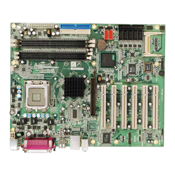
IMBA-8654 Motherboard 1.2.1 IMBA-8654 Overview Photo The IMBA-8654 has a wide variety of internal and external peripheral connectors. The peripheral connectors are connected to devices including storage devices, display devices and parallel communications devices. A labeled photo of the peripheral connectors is shown in Figure 1-1. -
Page 22: Imba-8654 Peripheral Connectors And Jumpers
2 x Serial ATA (SATA) drive connectors 7 x Serial port connectors 1 x SPDIF connector 4 x USB connectors The IMBA-8654 has the following external peripheral interface connectors on the board rear panel: 1 x PS/2 dual keyboard/mouse connector 1 x parallel port connector... -
Page 23: Technical Specifications
The IMBA-8654 has the following on-board jumpers: CF Master/Slave Selection Clear CMOS COM3 RS-422/485 Selection 1.2.3 Technical Specifications IMBA-8654 technical specifications are listed in Table 1-1. Detailed descriptions of each specification can be found in Chapter 2. Specification IMBA-8654 Form Factor ATX motherboard LGA775 Intel®... -
Page 24: Table 1-1: Technical Specifications
IMBA-8654 Motherboard Specification IMBA-8654 Two 40-pin IDE connects up to four Ultra ATA33/66/100 devices Floppy Disk One FDD connector supports one floppy disk drive SATA Two SATA 3Gb/s drives supported Keyboard/mouse One PS/2 connector supports mouse and keyboard connectivity Watchdog Timer Software programmable 1-255 sec. -
Page 25: Detailed Specifications
IMBA-8654 Motherboard Chapter Detailed Specifications Page 7... -
Page 26: Overview
IMBA-8654 Motherboard 2.1 Overview This chapter describes the specifications and on-board features of the IMBA-8654 in detail. 2.2 Dimensions 2.2.1 Board Dimensions The dimensions of the board are listed below and shown in Figure 2-1. Length: 305 mm Width: 244 mm... -
Page 27: External Interface Panel Dimensions
IMBA-8654 Motherboard 2.2.2 External Interface Panel Dimensions External peripheral interface connector panel dimensions are shown in Figure 2-2. Figure 2-2: External Interface Panel Dimensions (mm) Page 9... -
Page 28: Data Flow
IMBA-8654 Motherboard 2.3 Data Flow Figure 2-3 shows the data flow between the two on-board chipsets and other components installed on the motherboard and described in the following sections of this chapter. Figure 2-3: Data Flow Block Diagram Page 10... -
Page 29: Compatible Processors
2.4 Compatible Processors 2.4.1 CPU Overview LGA775 Intel® Pentium® 4, Intel® Pentium® D and Intel® Celeron® D processors can be ® ® ® installed on the IMBA-8654 motherboard. The Intel Pentium 4 processors and the Intel ® ® ® Celeron... -
Page 30: Supported Intel® Pentium® D Processors
IMBA-8654 Motherboard 2.4.3 Supported Intel® Pentium® D Processors Specifications for the compatible Intel® Pentium® D processors are listed in Table 2-2. CPU Speed Bus Speed Mfg. Tech Cache Package Processor No. 3.60 GHz 800 MHz 65 nm 4 MB LGA775 3.40 GHz... - Page 31 IMBA-8654 Motherboard Host Interface Support Intel® Pentium® 4 processors with 512-KB L2 cache on 0.13 micron process / Pentium 4 processor on 90 nm process 64-bit FSB frequencies of 400 MHz (100 MHz bus clock), 533 MHz (133 MHz bus clock), and 800 MHz (200 MHz bus clock). Maximum theoretical BW of 6.4 GB/s.
- Page 32 IMBA-8654 Motherboard AGP Interface Support A single AGP device AGP 3.0 with 4X / 8X AGP data transfers and 4X / 8X fast writes, respectively 32-bit 4X/8X data transfers and 4X/8X fast writes Peak BW of 2 GB/s. AGP 2.0 1X/4X AGP data transfers and 4X fast writes...
-
Page 33: Intel® 865G Memory Support
The Intel® 865G supports four, 1GB, 333/400MHz dual channel DDR SDRAM DIMMs. Four 184-pin memory sockets on the IMBA-8654 enable a maximum of 4GB of memory to be installed on the system. The memory sockets are shown in Figure 2-4. - Page 34 IMBA-8654 Motherboard Anti-aliased Lines Support Sprite Points Support High-Quality/Performance Texture Engine Per Pixel Perspective Corrected Texture Mapping Single Pass Quad Texture Compositing Enhanced Texture Blending Functions 12 Level of Detail MIP Map Sizes from 1x1 to 2Kx2K All texture formats including 32-bit RGBA and 8-bit palettes...
- Page 35 IMBA-8654 Motherboard 16- and 24-bit W Buffering 8-bit Stencil Buffering Double and Triple Render Buffer Support 16- and 32-bit Color Destination Alpha Vertex Cache Maximum 3D Resolution Supported: 1600x1200x32 @ 85Hz Fast Clear Support Video DVD/PC-VCR Hardware Motion Compensation for MPEG2...
-
Page 36: Intel ® Ich5 Southbridge Chipset
ICH5 Southbridge Chipset ® 2.6.1 Intel ICH5 Overview The ICH5 southbridge chipset on the IMBA-8654 has the features are listed below. PCI Local Bus Specification, Revision 2.3 with support for 33 MHz PCI operations. PCI slots (supports up to 6 Req/Gnt pairs) -
Page 37: Intel ® Ich5 Ide Interface
IMBA-8654 Motherboard Back left Back right Center Subwoofer ® 2.6.3 Intel ICH5 IDE Interface The integrated IDE interface on the ICH5 southbridge supports up to four IDE hard disks and ATAPI devices, PIO IDE transfers up to 16MB/s and Ultra ATA transfers of 100MB/s. -
Page 38: Intel ® Ich5 Pci Interface
IMBA-8654 Motherboard ® 2.6.5 Intel ICH5 PCI Interface The PCI interface on the ICH5 is compliant with the PCI Revision 2.3 implementation. Some of the features of the PCI interface are listed below. PCI Revision 2.3 compliant 33MHz 5V tolerant PCI signals (except PME#) -
Page 39: Intel ® Ich5 Usb Controller
IMBA-8654 Motherboard ® 2.6.8 Intel ICH5 USB Controller Up to eight high-speed, full-speed or low-speed USB devices are supported by the ICH5. High-speed USB 2.0, with data transfers of up to 480MB/s, is enabled with the ICH5 integrated Enhanced Host Controller Interface (EHCI) compliant host controller. USB full-speed and low-speed signaling is supported by the four ICH5 integrated Universal Host Controller Interface (UHCI) controller. -
Page 40: Lpc Bus Components
IMBA-8654 Motherboard Fully compliant with IEEE 802.3, IEEE 802.3u, IEEE 802.3ab Supports IEEE 802. IP Layer 2 Priority Encoding Supports IEEE 802. IQ VLAN tagging Serial EEPROM 3.3V signaling, 5V PCI I/O tolerant Transmit/Receive FIFO support Supports power down/link down power saving Supports PCI Message Signaled Interrupt (MSI) 2.8 LPC Bus Components... -
Page 41: Super I/O Lpc Interface
IMBA-8654 Motherboard LPC Interface PC98/99, DPM and ACPI Compliant Hardware Monitor Fan Speed Controller Two 16C550 UARTs for serial port control One IEEE 1284 Parallel Port Floppy Disk Controller Supports IrDA and ASKIR protocols Watchdog Timer Serial IRQ Support Vbat & Vcch Support... -
Page 42: Super I/O Fan Speed Controller
EPP, IEEE 1284 compliant High-speed mode ECP, IEEE 1284 compliant 2.9 Environmental and Power Specifications 2.9.1 System Monitoring Three thermal inputs on the IMBA-8654 Super I/O Enhanced Hardware Monitor the following temperatures: CPU Temperature System Temperature #1 System Temperature #2... -
Page 43: Operating Temperature And Temperature Control
5VSB The IMBA-8654 Super I/O Enhanced Hardware Monitor also monitors the following voltages internally: VBAT The IMBA-8654 Super I/O Enhanced Hardware Monitor also monitors the following fan speeds: CPU Fan speed System Fan speed The values for the above environmental parameters are all recorded in the BIOS Hardware Health Configuration menu. -
Page 44: Power Consumption
IMBA-8654 Motherboard 2.9.3 Power Consumption Table 2-5 shows the power consumption parameters for the IMBA-8654 running with an ® Intel Pentium® D 3.6GHz/800 MHz CPU with 1GB DDR 400MHz of memory. Voltage Current +3.3V 0.7A 5VSB 0.7A 5.9A +12V 8.57A -12V 0.2A... -
Page 45: Unpacking
IMBA-8654 Motherboard Chapter Unpacking Page 27... -
Page 46: Anti-Static Precautions
Electrostatic discharge (ESD) can cause serious damage to electronic components, including the IMBA-8654. Dry climates are especially susceptible to ESD. It is critical that the following anti-static precautions are strictly adhered to whenever handling the IMBA-8654 or any other electrical component. -
Page 47: Unpacking
When the IMBA-8654 is unpacked, please do the following: Follow the anti-static precautions outlined in Section 3.1. Make sure the packing box is facing upwards so the IMBA-8654 does not fall out of the box. Make sure all the components shown in Section 3.3 are present. -
Page 48: Table 3-1: Package List Contents
IMBA-8654 Motherboard Quantity Item and Part Number Image Dual RS-232 cable (P/N: 32200-004101-RS) RS-232 cable (P/N: 32200-029400-RS) RS-422/485 cable (P/N: 19800-000063-RS) SATA cables (P/N: 32000-062800-RS) SATA power cable (P/N: 32100-088600-RS) I/O Shielding (P/N: 45002-0804C0-00-RS) Mini jumper Pack (P/N: 33100-000079-RS) Quick Installation Guide... -
Page 49: Optional Components
IMBA-8654 Motherboard 3.3.2 Optional Components The following optional components are available from IEI. Item and Part Number Image CPU cooling kit (P/N: CF-520-RS) CPU cooling kit (P/N: CF-775A-RS) FDD cable (P/N: 32200-0000-17-RS) Dual USB cable (P/N: CB-USB02-RS) Table 3-2: Optional Components... -
Page 50: This Page Is Intentionally Left Blank
IMBA-8654 Motherboard THIS PAGE IS INTENTIONALLY LEFT BLANK Page 32... -
Page 51: Connector Pinouts
IMBA-8654 Motherboard Chapter Connector Pinouts Page 33... -
Page 52: Peripheral Interface Connectors
Figure 4-1 shows the on-board peripheral connectors, rear panel peripheral connectors and on-board jumpers. Figure 4-1: Connector and Jumper Locations 4.1.2 Peripheral Interface Connectors Table 4-1 shows a list of the peripheral interface connectors on the IMBA-8654. Detailed descriptions of these connectors can be found below. Page 34... - Page 53 IMBA-8654 Motherboard Connector Type Label +12V ATX power connector 4-pin header CPU12V1 AGP slot 66-pin AGP 8X slot AGP1 ATX power connector 24-pin header ATX1 Audio connector 8-pin header Auxiliary audio connector 4-pin header AUX1 CD-in connector 4-pin header CD_IN1...
-
Page 54: External Peripheral Interface Panel Connectors
USB connector 8-pin header USB3 Table 4-1: Peripheral Interface Connectors 4.1.3 External Peripheral Interface Panel Connectors Table 4-2 lists the external peripheral interface panel connectors on the IMBA-8654. Detailed descriptions of these connectors can be found in. Connector Type Label... -
Page 55: Atx Power Supply Connector (4-Pins)
IMBA-8654 Motherboard 4.2.1 ATX Power Supply Connector (4-pins) CN Label: CPU12V1 CN Type: 4-pin ATX power connector (1x4) CN Location: See Figure 4-2 CN Pinouts: See Table 4-3 The 4-pin ATX power supply connector is connected to a +12V ATX power supply. -
Page 56: Agp Connector (66-Pins)
IMBA-8654 Motherboard 4.2.2 AGP Connector (66-pins) CN Label: AGP1 CN Type: 66-pin AGP slot CN Location: See Figure 4-3 CN Pinouts: See Table 4-4 Use the 66-pin AGP slot to connect an AGP 3.0 compliant graphics card. Page 38... -
Page 57: Figure 4-3: Agp Slot Location
IMBA-8654 Motherboard Figure 4-3: AGP Slot Location Page 39... - Page 58 IMBA-8654 Motherboard OVRCNT# Vddq1.5 Vddq1.5 5.0V TYPEDET# AD21 AD22 5.0V GC_DET# AD19 AD20 USB+ USB- AD17 AD18 INTB# INTA# C#/BE2 AD16 RST# Vddq1.5 Vddq1.5 IRDY FRAME VCC3.3 VCC3.3 MB _DET# DBI_HI DEVSEL TRDY DBI_LO Vddq1.5 STOP SBA0# SBA1# PERR PME# VCC3.3...
-
Page 59: Atx Power Supply Connector (24-Pins)
IMBA-8654 Motherboard AD23 C#/BE3 AGPVrefcg AGPVrefgc Table 4-4: AGP Slot Pinouts 4.2.3 ATX Power Supply Connector (24-pins) CN Label: PWR1 CN Type: 24-pin ATX power connector (2x12) CN Location: See Figure 4-4 CN Pinouts: See Table 4-5 The 24-pin ATX power supply connector is connected to a ATX power supply. -
Page 60: Table 4-5: Atx Power Connector Pinouts
IMBA-8654 Motherboard DESCRIPTION DESCRIPTION 3.3V01 3.3V04 3.3V02 -12V COM01 +5V01 PS-ON COM02 COM04 +5V02 COM05 COM03 COM06 PWR-OK 5VSB +5V03 +12V01 +5V04 +12V02 +5V05 3.3V03 COM07 Table 4-5: ATX Power Connector Pinouts Page 42... -
Page 61: Audio Connector (8-Pin)
IMBA-8654 Motherboard 4.2.4 Audio Connector (8-pin) CN Label: CN Type: 7-pin header CN Location: See Figure 4-5 CN Pinouts: See Table 4-6 The 8-pin audio connector is connected to external audio devices including speakers and microphones for the input and output of audio signals to and from the system. -
Page 62: Auxiliary Audio Connector (4-Pin)
IMBA-8654 Motherboard 4.2.5 Auxiliary Audio Connector (4-pin) CN Label: AUX1 CN Type: 4-pin header CN Location: See Figure 4-6 CN Pinouts: See Table 4-7 The 4-pin auxiliary audio connector provides a second audio input to the system. Figure 4-6: Auxiliary Audio Connector Location (4-pin) -
Page 63: Cd-In Connector
IMBA-8654 Motherboard 4.2.6 CD-In Connector CN Label: CD_IN1 CN Type: 4-pin header CN Location: See Figure 4-7 CN Pinouts: See Table 4-8 The 4-pin CD-in connector connects a CD to the system. Figure 4-7: CD-In Connector DESCRIPTION Table 4-8: CD-In Connector... -
Page 64: Compact Flash Socket
IMBA-8654 Motherboard 4.2.7 Compact Flash Socket CN Label: CN Type: 50-pin header (2x25) CN Location: See Figure 4-8 CN Pinouts: See Table 4-9 A CF Type I or Type II memory card inserts into the CF socket on the motherboard. -
Page 65: Figure 4-8: Cf Card Socket Location
IMBA-8654 Motherboard Figure 4-8: CF Card Socket Location DESCRIPTION DESCRIPTION GROUND VCC-IN CHECK1 DATA 3 DATA 11 DATA 4 DATA 12 DATA 5 DATA 13 DATA 6 DATA 14 DATA 7 DATA 15 HDC_CS0# HDC_CS1 GROUND IOR# Page 47... -
Page 66: Table 4-9: Cf Card Socket Pinouts
IMBA-8654 Motherboard DESCRIPTION DESCRIPTION IOW# VCC_COM IRQ15 VCC_COM VCC_COM CSEL HDD_RESET IORDY SDREQ SDACK# HDD_ACTIVE# DATA 0 66DET DATA 1 DATA 8 DATA 2 DATA 9 DATA 10 VCC-IN CHECK2 GROUND Table 4-9: CF Card Socket Pinouts Page 48... -
Page 67: Digital Input/Output (Dio) Connector
IMBA-8654 Motherboard 4.2.8 Digital Input/Output (DIO) Connector CN Label: DIO1 CN Type: 10-pin header (2x5) CN Location: See Figure 4-9 CN Pinouts: See Table 4-10 The digital input/output connector is managed through a Super I/O chip. The DIO connector pins are user programmable. -
Page 68: Fan Connectors
IMBA-8654 Motherboard 4.2.9 Fan Connectors CN Label: CPU_FAN1, SYS_FAN1 CPU_FAN1: 4-pin wafer connector CN Type: SYS_FAN1: 3-pin wafer connector CN Location: See Figure 4-10 CN Pinouts: See Table 4-11 The FAN1, FAN2 and FAN3 cooling fan connectors provide a 12V current to the cooling fans. -
Page 69: Floppy Disk Connector
IMBA-8654 Motherboard CPU_FAN1 SYS_FAN1 +12V +12V Rotation Signal Rotation Signal Control Table 4-11: Fan Connectors Pinouts 4.2.10 Floppy Disk Connector CN Label: FDD1 CN Type: 34-pin header (2x17) CN Location: See Figure 4-11 CN Pinouts: See Table 4-12 The floppy disk connector is connected to a floppy disk drive. -
Page 70: Front Panel Audio Connector
IMBA-8654 Motherboard DESCRIPTION DESCRIPTION REDUCE WRITE INDEX# MOTOR ENABLE A# DRIVE SELECT B# DRIVE SELECT A# MOTOR ENABLE B# DIRECTION# STEP# WRITE DATA# WRITE GATE# TRACK 0# WRITE PROTECT# READ DATA# SIDE 1 SELECT# DISK CHANGE# Table 4-12: FDC Connector Pinouts 4.2.11 Front Panel Audio Connector... -
Page 71: Figure 4-12: Front Panel Audio Connector Pinout Locations
IMBA-8654 Motherboard Figure 4-12: Front Panel Audio Connector Pinout Locations DESCRIPTION DESCRIPTION MIC IN GROUND MIC BIAS LINE OUT (R) LINE OUT (R) Return LINE OUT (L) LINE OUT (L) Return Table 4-13: Front Panel Audio Connector Pinouts Page 53... -
Page 72: Front Panel Connector (14-Pin)
IMBA-8654 Motherboard 4.2.12 Front Panel Connector (14-pin) CN Label: F_PANEL1 CN Type: 14-pin header (2x7) CN Location: See Figure 4-13 CN Pinouts: See Table 4-14 The front panel connector connects to external switches and indicators to monitor and controls the motherboard. These indicators and switches include:... -
Page 73: Table 4-14: Front Panel Connector Pinouts
IMBA-8654 Motherboard FUNCTION DESCRIPTION BUZZER BUZZER- RESET RESET GROUND HDD LED IDE_LED+ IDE_LED- POWER LED PWR_LED+ PWR_LED- POWER BUTTON GROUND POWER BUTTON Table 4-14: Front Panel Connector Pinouts Page 55... -
Page 74: Ide Connector (40-Pin)
IDE1, IDE2 CN Type: 40-pin box header (2x20) CN Location: See Figure 4-14 CN Pinouts: See Table 4-15 One 40-pin IDE device connector on the IMBA-8654 supports connectivity to two hard disk drives. Figure 4-14: IDE Device Connector Locations Page 56... -
Page 75: Table 4-15: Ide Connector Pinouts
IMBA-8654 Motherboard DESCRIPTION DESCRIPTION RESET# GROUND DATA 7 DATA 8 DATA 6 DATA 9 DATA 5 DATA 10 DATA 4 DATA 11 DATA 3 DATA 12 DATA 2 DATA 13 DATA 1 DATA 14 DATA 0 DATA 15 GROUND IDE DRQ... -
Page 76: Infrared Interface Connector (5-Pin)
IMBA-8654 Motherboard 4.2.14 Infrared Interface Connector (5-pin) CN Label: CN Type: 5-pin header (1x5) CN Location: See Figure 4-15 CN Pinouts: See Table 4-16 The infrared interface connector supports both Serial Infrared (SIR) and Amplitude Shift Key Infrared (ASKIR) interfaces. -
Page 77: Pci Slot
IMBA-8654 Motherboard 4.2.15 PCI Slot CN Label: PCI1 to PCI6 CN Type: PCI Slot CN Location: See Figure 4-16 CN Pinouts: See Table 4-17 The PCI slot enables a PCI expansion module to be connected to the board. Page 59... -
Page 78: Figure 4-16: Pci Slot Location
IMBA-8654 Motherboard Figure 4-16: PCI Slot Location Page 60... - Page 79 IMBA-8654 Motherboard DESCRIPTION DESCRIPTION TRST -12V +12V INTA INTC INTB INTD RESERVED3 PRSNT1 RESERVED1 RESERVED4 PRSNT2 3.3V_AUX RESERVED2 AD30 AD31 +3.3V AD29 AD28 AD26 AD27 AD25 AD24 +3.3V IDSEL C/BE3 +3.3V AD23 AD22 AD20 AD21 AD19 AD18 +3.3V AD16 AD17...
-
Page 80: Table 4-17: Pci Slot
IMBA-8654 Motherboard DESCRIPTION DESCRIPTION +3.3V C/BE2 FRAME IRDY TRDY +3.3V DEVSEL STOP +3.3V LOCK SDONE PERR +3.3V SERR +3.3V AD15 C/BE1 +3.3V AD14 AD13 AD11 AD12 AD10 C/BE0 +3.3V +3.3V REQ64 ACK64 Table 4-17: PCI Slot Page 62... -
Page 81: Sata Drive Connectors
IMBA-8654 Motherboard 4.2.16 SATA Drive Connectors CN Label: SATA1, SATA2 CN Type: 7-pin SATA drive connectors CN Location: See Figure 4-17 CN Pinouts: See Table 4-18 The SATA drive connectors are connected to SATA 3Gb/s disk drives that transfer data at speeds as high as 3.0Gb/s. -
Page 82: Table 4-18: Sata Drive Connector Pinouts
IMBA-8654 Motherboard DESCRIPTION Table 4-18: SATA Drive Connector Pinouts Page 64... -
Page 83: Serial Port Connector (Rs-232/422/485)
IMBA-8654 Motherboard 4.2.17 Serial Port Connector (RS-232/422/485) RS-323: COM2, COM4, COM5, COM6 CN Label: RS-232/422/485: COM3 (by jumper) 10-pin box header (2x5) CN Type: CN Location: See Figure 4-18 CN Pinouts: See Table 4-19 The 10-pin COM2, COM4, COM5 and COM6 serial port connectors provide RS-232 serial communications channels that can be connected to external RS-232 serial port devices. -
Page 84: Serial Port Connector (Rs-422/485)
IMBA-8654 Motherboard DESCRIPTION DESCRIPTION SOUT CTS- DTR- Table 4-19: Serial Port Connector Pinouts 4.2.18 Serial Port Connector (RS-422/485) CN Label: CN Type: 4-pin header CN Location: See Figure 4-19 CN Pinouts: See Table 4-20 The 4-pin serial port connector provides RS-422/485 serial communications channels that can be connected to external RS-422/485 serial port devices. -
Page 85: Spdif Connector
IMBA-8654 Motherboard DESCRIPTION TXD1+ TXD1- RXD1+ RXD1- Table 4-20: Serial Port Connector (RS-422/485) Pinouts 4.2.19 SPDIF Connector CN Label: SPDIF1 CN Type: 5-pin header CN Location: See Figure 4-20 CN Pinouts: See Table 4-21 Use the SPDIF connector to connect digital audio devices to the system. -
Page 86: Table 4-21: Spdif Connector Pinouts
IMBA-8654 Motherboard DESCRIPTION VCC AUDIO SPDIF OUT GND AUDIO SPDIF IN Table 4-21: SPDIF Connector Pinouts Page 68... -
Page 87: Usb Connectors (Internal)
IMBA-8654 Motherboard 4.2.20 USB Connectors (Internal) CN Label: USB2, USB3 CN Type: 8-pin header (2x4) CN Location: See Figure 4-21 CN Pinouts: See Table 4-22 The 2x4 USB pin connectors each provide connectivity to two USB 1.1 or two USB 2.0 ports. -
Page 88: External Peripheral Interface Connectors
IMBA-8654 Motherboard 4.3 External Peripheral Interface Connectors The external peripheral interface connectors on the back panel are connected to devices externally when the IMBA-8654 is installed in a chassis. The peripheral connectors on the rear panel are: 1 x Keyboard/mouse connector... -
Page 89: Parallel Port Connector
DB-25 CN Location: See Figure 4-22 (labeled number 2) CN Pinouts: See Figure 4-24 and Table 4-24 These ports are usually connected to a printer. IMBA-8654 includes one on-board parallel ports accessed through one 25-pin D-type female connector. Page 71... -
Page 90: Usb Connectors
IMBA-8654 Motherboard Figure 4-24: Parallel Port Connector Pinout Locations Description Description STROBE# DATA 0 DATA 1 DATA 2 DATA 3 DATA 4 DATA 5 DATA 6 DATA 7 ACKNOWLEDGE BUSY PAPER EMPTY PRINTER SELECT AUTO FORM FEED # ERROR# INITIALIZE... -
Page 91: Ethernet Connector
IMBA-8654 Motherboard USB devices connect directly to the USB connectors on the external peripheral connector panel. Figure 4-25: USB Connector Pinout Locations DESCRIPTION DESCRIPTION USBD0- USBD0- USBD0+ USBD0+ Table 4-25: USB Connector Pinouts 4.3.4 Ethernet Connector CN Label: LAN/USB1 CN Type:... -
Page 92: Figure 4-26: Ethernet Connector Pinout Locations
IMBA-8654 Motherboard Figure 4-26: Ethernet Connector Pinout Locations DESCRIPTION DESCRIPTION TX+ (or MDX0+) N/C (or MDX2-) TX- (or MDX0-) RX- (or MDX1-) RX+ (or MDX1+) N/C (or MDX3+) N/C (or MDX2+) N/C (or MDX3-) MDX0+ MDX2- MDX0- MDX1- MDX1+ MDX3+... -
Page 93: Audio Connectors
IMBA-8654 Motherboard The RJ-45 Ethernet connector has two status LEDs, one green and one yellow. The green LED indicates activity on the port and the yellow LED indicates the port is linked (Table 4-27). SPEED LED LINK LED Status Description... -
Page 94: Vga Connector
IMBA-8654 Motherboard 4.3.6 VGA Connector CN Label: CN Type: HD-D-sub 15 Female connector CN Location: See Figure 4-22 (labeled 6) CN Pinouts: See Figure 4-29 and Table 4-28 The standard HD-D-sub 15 female connector connects to a CRT or LCD monitor. -
Page 95: On-Board Jumpers
IMBA-8654 Motherboard The serial connector on the external interface panel provides serial connection in the RS-232 mode. Figure 4-30: Serial Communications Connector Pinout Locations DESCRIPTION DATA CARRIER DETECT (DCD) RECEIVE DATA (RXD) TRANSMIT DATA (TXD) DATA TERMINAL READY (DTR) GROUND (GND) - Page 96 IMBA-8654 Motherboard THIS PAGE IS INTENTIONALLY LEFT BLANK Page 78...
-
Page 97: Installation
IMBA-8654 Motherboard Chapter Installation Page 79... -
Page 98: Anti-Static Precautions
Electrostatic discharge (ESD) can cause serious damage to electronic components, including the IMBA-8654. Dry climates are especially susceptible to ESD. It is therefore critical that whenever the IMBA-8654, or any other electrical component is handled, the following anti-static precautions are strictly adhered to. -
Page 99: Installation Considerations
IMBA-8654 is installed. All installation notices pertaining to the installation of the IMBA-8654 should be strictly adhered to. Failing to adhere to these precautions may lead to severe damage of the IMBA-8654 and injury to the person installing the motherboard. 5.2.1 Installation Notices... -
Page 100: Installation Checklist
IMBA-8654 Motherboard When working with the IMBA-8654, make sure that it is disconnected from all power supplies and that no electricity is being fed into the system. Before and during the installation of the IMBA-8654 DO NOT: Remove any of the stickers on the PCB board. These stickers are required for warranty validation. -
Page 101: Cpu, Cpu Cooling Kit And Dimm Installation
Running a CPU without a cooling kit may also result in injury to the user. The CPU, CPU cooling kit and DIMM are the most critical components of the IMBA-8654. If any of these components is not installed, the IMBA-8654 cannot operate. -
Page 102: Figure 5-1: Intel Lga775
The LGA775 is shown in Figure 5-1. Figure 5-1: Intel LGA775 To install a LGA775 CPU onto the IMBA-8654, follow the steps below: WARNING! When handling the CPU, only hold it on the sides. DO NOT touch the pins at the bottom of the CPU. -
Page 103: Figure 5-2: Remove The Cpu Socket Protective Shield
IMBA-8654 Motherboard Figure 5-2: Remove the CPU Socket Protective Shield Step 2: Open the socket. Disengage the load lever by pressing the lever down and slightly outward to clear the retention tab. Rotate the load lever to a fully open position. -
Page 104: Figure 5-4: Insert The Lga775 Cpu
IMBA-8654 Motherboard Step 4: Orientate the CPU properly. Make sure the IHS (Integrated Heat Sink) side is facing upward. Step 5: Correctly position the CPU. Match the Pin 1 mark with the cut edge on the CPU socket. Step 6: Align the CPU pins. -
Page 105: Lga775 Cooling Kit Installation
WARNING! It is strongly recommended that the original heat sink and cooler provided by Intel not be used on the IMBA-8654. IEI’s cooling kits include a support bracket that is combined with the heat sink mounted on the CPU to counterweigh and balance the load on both sides of the PCB. -
Page 106: Figure 5-6: Securing The Heat Sink To The Pcb Board
Step 6: Connect the fan cable. Connect the cooling kit fan cable to the fan connector on the IMBA-8654. Carefully route the cable and avoid heat generating chips and blades.Step 0: Page 88... -
Page 107: Dimm Installation
5.3.3 DIMM Installation WARNING! Using incorrectly specified DIMM may cause permanently damage the IMBA-8654. Please make sure the purchased DIMM complies with the memory specifications of the IMBA-8654. DIMM specifications compliant with the IMBA-8654 are listed in Chapter 2. To install a DIMM into a DIMM socket, please follow the steps below and refer to Figure 5-7. -
Page 108: Jumper Settings
OPEN a jumper means removing the Figure 5-8: Jumper Locations plastic clip from a jumper. Before the IMBA-8654 is installed in the system, the jumpers must be set in accordance with the desired configuration. The jumpers on the IMBA-8654 are listed in Table 5-1. Description... -
Page 109: Cf Master/Slave Selection
IMBA-8654 Motherboard Figure 5-9: Jumper Locations 5.4.1 CF Master/Slave Selection Jumper Label: Jumper Type: 2-pin header Jumper Settings: See Table 5-2 Jumper Location: See Figure 5-9 The CF Master/Slave Selection jumper sets the CF Type I card or CF Type II cards as either the slave device or the master device. -
Page 110: Clear Cmos Jumper
Jumper Location: See Figure 5-9 If the IMBA-8654 fails to boot due to improper BIOS settings, the clear CMOS jumper clears the CMOS data and resets the system BIOS information. To do this, use the jumper cap to close pins 2 and 3 for a few seconds then reinstall the jumper clip back to pins 1 and 2. -
Page 111: Com3 Mode Selection
5.5 Chassis Installation 5.5.1 Airflow WARNING! Airflow is critical to the cooling of the CPU and other onboard components. The chassis into which the IMBA-8654 is placed must have air vents to allow proper airflow to cool the system components. Page 93... -
Page 112: Internal Peripheral Device Connections
IMBA-8654 Motherboard The IMBA-8654 must be installed in a chassis with ventilation holes on the sides allowing airflow to travel over the heat sink surface. In a system with an individual power supply unit, the cooling fan of a power supply can also help generate airflow over the board surface. -
Page 113: Ata Flat Cable Connection
5.6.2 ATA Flat Cable Connection The ATA 66/100 flat cable connects to an IDE device. Follow the instructions below to connect an IDE HDD to the IMBA-8654. Step 1: Locate the IDE connector. The locations of the IDE device connectors are shown in Chapter 3. -
Page 114: Dual Rs-232 Cable With Slot Bracket
IMBA-8654 Motherboard 5.6.3 Dual RS-232 Cable with Slot Bracket The dual RS-232 cable consists of two serial port connectors attached to a serial communications cable that is then attached to two bracket mounted D-sub 9 male connectors. To install the dual RS-232 cable, please follow the steps below. -
Page 115: Single Rs-232 Cable With Slot Bracket
IMBA-8654 Motherboard 5.6.4 Single RS-232 Cable with Slot Bracket The single RS-232 cable consists of one serial port connectors attached to a serial communications cable that is then attached to a D-sub 9 male connector that is mounted onto a bracket. To install the single RS-232 cable, please follow the steps below. -
Page 116: Dual Rs-422/485 Cables
IMBA-8654 Motherboard 5.6.5 Dual RS-422/485 Cables The IMBA-8654 is shipped with one dual serial port connector cable. The dual serial port connector cable connects the serial port connectors on the cable to the RS-422/485 serial port connectors on the IMBA-8654. Follow the steps below to connect the dual serial port connector cable. -
Page 117: Sata Drive Connection
DB-9 connectors should be secured to the chassis with retention screws.Step 0: 5.6.6 SATA Drive Connection The IMBA-8654 is shipped with SATA drive cables and SATA drive power cable. Follow the steps below to connect the SATA drives to the motherboard. Step 1: Locate the connectors. -
Page 118: External Peripheral Interface Connection
IMBA-8654 Motherboard Step 3: Connect the cable to the SATA disk. Connect the connector on the other end of the cable to the connector at the back of the SATA drive. See Figure 5-15. Step 4: Connect the SATA power cable. Connect the SATA power connector to the back of the SATA drive. -
Page 119: Ps/2 Keyboard/Mouse Connection
5.7.1 PS/2 Keyboard/Mouse Connection The IMBA-8654 has a dual PS/2 connector on the external peripheral interface panel. The dual PS/2 connector is used to connect to a keyboard and mouse to the system. Follow the steps below to connect a keyboard and mouse to the IMBA-8654. -
Page 120: Parallel Device Connection
IMBA-8654 Motherboard 5.7.2 Parallel Device Connection The IMBA-8654 has a single female DB-25 connector on the external peripheral interface panel for parallel devices. Follow the steps below to connect a parallel device to the IMBA-8654. Step 1: Locate the DB-25 connector. The location of the DB-25 connector is shown in Chapter 3. -
Page 121: Ethernet Connection
5.7.4 USB Connection The external USB Series "A" receptacle connectors provide easier and quicker access to external USB devices. Follow the steps below to connect USB devices to the IMBA-8654. Step 1: Locate the USB Series "A" receptacle connectors. The location of the USB Series "A"... -
Page 122: Audio Connection
Audio signals are interfaced through three phone jack connections. The red phone jack is for Mic In, blue is for Line In and green is for Speaker Out. Follow the steps below to connect audio devices to the IMBA-8654. Step 1: Locate the audio phone jacks. -
Page 123: Vga Monitor Connection
IMBA-8654 Motherboard Figure 5-20: Audio Connectors 5.7.6 VGA Monitor Connection The IMBA-8654 has a single female DB-15 connector on the external peripheral interface panel for a VGA monitor. Follow the steps below to connect a VGA monitor to the IMBA-8654. -
Page 124: Serial Device Connection
Step 0: 5.7.7 Serial Device Connection The IMBA-8654 has a single female DB-9 connector on the external peripheral interface panel for a serial device. Follow the steps below to connect a serial device to the IMBA-8654. -
Page 125: Figure 5-22: Serial Device Connector
IMBA-8654 Motherboard Figure 5-22: Serial Device Connector Step 3: Secure the connector. Secure the serial device connector to the external interface by tightening the two retention screws on either side of the connector. Step 0: Page 107... - Page 126 IMBA-8654 Motherboard THIS PAGE IS INTENTIONALLY LEFT BLANK Page 108...
-
Page 127: Ami Bios
IMBA-8654 Motherboard Chapter AMI BIOS Page 109... -
Page 128: Introduction
IMBA-8654 Motherboard 6.1 Introduction A licensed copy of AMI BIOS is preprogrammed into the ROM BIOS. The BIOS setup program allows users to modify the basic system configuration. This chapter describes how to access the BIOS setup program and the configuration options that may be changed. -
Page 129: Getting Help
IMBA-8654 Motherboard Function F1 key General help, only for Status Page Setup Menu and Option Page Setup Menu F2 /F3 key Change color from total 16 colors. F2 to select color forward. F10 key Save all the CMOS changes, only for Main Menu Table 6-1: BIOS Navigation Keys 6.1.3 Getting Help... -
Page 130: Main
IMBA-8654 Motherboard 6.2 Main The Main BIOS menu (BIOS Menu 1) appears when the BIOS Setup program is entered. The Main menu gives an overview of the basic system information. BIOS Menu 1: Main System Overview The System Overview lists a brief summary of different system components. The fields in System Overview cannot be changed. -
Page 131: Advanced
IMBA-8654 Motherboard System Time [xx:xx:xx] Use the System Time option to set the system time. Manually enter the hours, minutes and seconds. System Date [xx/xx/xx] Use the System Date option to set the system date. Manually enter the day, month and year. -
Page 132: Cpu Configuration
IMBA-8654 Motherboard BIOS Menu 2: Advanced 6.3.1 CPU Configuration Use the CPU Configuration menu (BIOS Menu 3) to view detailed CPU specifications and configure the CPU. BIOS Menu 3: CPU Configuration The CPU Configuration menu lists the following CPU details: Module Version: xx.xx... - Page 133 IMBA-8654 Motherboard Cache L1: Lists the CPU L1 cache size Cache L2: Lists the CPU L2 cache size Ratio Actual Value: Displays the ratio at which the CPU is actually operating The following CPU Configuration menu items can be configured.
-
Page 134: Ide Configuration
IMBA-8654 Motherboard Execute Bit Disable [Enabled] Use the Execute Bit Disable BIOS function to protect the system from buffer overflow attacks. Disabled Code can be executed in any memory area. Code execution in data-only memory pages is Enabled EFAULT prohibited. -
Page 135: Bios Menu 4: Ide Configuration
IMBA-8654 Motherboard BIOS Menu 4: IDE Configuration IDE Configuration [P-ATA Only] Use the IDE Configuration option to enable\disable PATA channel and SATA channel. Disables all IDE ports. Disabled P-ATA Only Allows up to six devices, four parallel and two EFAULT serial. - Page 136 IMBA-8654 Motherboard on the secondary IDE channel are secondary master/slave, and the primary IDE channel is disabled. S-ATA Running Enhanced Mode [Yes] Use the S-ATA Running Enhanced Mode option to configure the on-board ATA/IDE controller to be in Enhanced mode. In this mode, IDE channels and SATA channels are separated.
- Page 137 IMBA-8654 Motherboard Use the S-ATA Ports Definition option to specify the definitions of the two serial ATA ports. This option is not available if the S-ATA Running Enhanced Mode option is set to If the IDE Configuration is set to P-ATA Only, the serial ATA ports are defined as 3rd master and 4th master.
-
Page 138: Ide Master, Ide Slave
IMBA-8654 Motherboard Primary IDE (Slave) Secindary IDE (Master) Secondary IDE (Slave) Third IDE (Master) Fourth IDE (Master) The IDE Configuration menu (BIOS Menu 4) allows changes to the configurations for the IDE devices installed in the system. If an IDE device is detected, and one of the above listed four BIOS configuration options are selected, the IDE configuration options shown in Section 6.3.2.1 appear. - Page 139 IMBA-8654 Motherboard Device: Lists the device type (e.g. hard disk, CD-ROM etc.) Type: Indicates the type of devices a user can manually select LBA Mode: Indicates whether the LBA (Logical Block Addressing) is a method of addressing data on a disk drive is supported or not.
- Page 140 IMBA-8654 Motherboard ARMD This option specifies an ATAPI Removable Media Device. These include, but are not limited to: LS-120 Page 122...
- Page 141 IMBA-8654 Motherboard LBA/Large Mode [Auto] Use the LBA/Large Mode option to disable or enable BIOS to auto detects LBA (Logical Block Addressing). LBA is a method of addressing data on a disk drive. In LBA mode, the maximum drive capacity is 137 GB.
- Page 142 IMBA-8654 Motherboard PIO mode 0 selected with a maximum transfer rate of 3.3MBps PIO mode 1 selected with a maximum transfer rate of 5.2MBps PIO mode 2 selected with a maximum transfer rate of 8.3MBps PIO mode 3 selected with a maximum transfer rate of 11.1MBps PIO mode 4 selected with a maximum transfer rate of 16.6MBps...
- Page 143 IMBA-8654 Motherboard UDMA1 Ultra DMA mode 0 selected with a maximum data transfer rate of 16.6MBps Ultra DMA mode 1 selected with a maximum data transfer UDMA1 rate of 25MBps UDMA2 Ultra DMA mode 2 selected with a maximum data transfer rate of 33.3MBps...
-
Page 144: Floppy Configuration
IMBA-8654 Motherboard Disabled Prevents the BIOS from using 32-bit data transfers. Enabled Allows BIOS to use 32-bit data transfers on supported EFAULT hard disk drives. 6.3.3 Floppy Configuration Use the Floppy Configuration menu to configure the floppy disk drive connected to the system. -
Page 145: Super Io Configuration
IMBA-8654 Motherboard 6.3.4 Super IO Configuration Use the IO Configuration menu (BIOS Menu 7) to set or change the configurations for the FDD controllers, parallel ports and serial ports. BIOS Menu 7: Super IO Configuration OnBoard Floppy Controller [Enabled] Use the OnBoard Floppy Controller to enable or disable the floppy controller. If a floppy disk is not being used in the system, disabling this option frees up system resources that can be redirected elsewhere in the system. - Page 146 IMBA-8654 Motherboard 3E8/IRQ4 Serial Port 1 I/O port address is 3E8 and the interrupt address is IRQ4 Serial Port 1 I/O port address is 2E8 and the interrupt 2E8/IRQ3 address is IRQ3 Serial Port1 Mode [Normal] Use the Serial Port1 Mode option to select the transmitting and receiving mode for the first serial port.
- Page 147 IMBA-8654 Motherboard Serial Port2 Mode [Normal] Use the Serial Port2 Mode option to select the Serial Port2 operational mode. Serial Port 2 mode is normal Normal EFAULT Serial Port 2 mode is IrDA IrDA ASK IR Serial Port 2 mode is ASK IR Parallel Port Address [Disabled] Use the Parallel Port Address option to select the parallel port base address.
- Page 148 IMBA-8654 Motherboard Parallel Port Mode [Normal] Use the Parallel Port Mode option to select the mode the parallel port operates in. The normal parallel port mode is the standard mode Normal EFAULT for parallel port operation. Bi-directional Parallel port outputs are 8-bits long. Inputs are accomplished by reading 4 of the 8 bits on the status register.
- Page 149 IMBA-8654 Motherboard Parallel Port IRQ [IRQ7] Use the Parallel Port IRQ selection to set the parallel port interrupt address. IRQ5 is assigned as the parallel port interrupt address IRQ5 IRQ7 is assigned as the parallel port interrupt address IRQ7 EFAULT...
- Page 150 IMBA-8654 Motherboard Serial port 4 I/O port address is 2E8 EFAULT Serial port 4 I/O port address is 2E0 Serial Port4 IRQ [10] Use the Serial Port4 IRQ option to select the interrupt address for serial port 4. Serial port 4 IRQ address is 3...
-
Page 151: Hardware Health Configuration
IMBA-8654 Motherboard Serial Port6 Address [2E0] Use the Serial Port6 Address option to select the interrupt address for serial port 6. Disabled No base address is assigned to serial port 6 Serial port 6 I/O port address is 3E8 Serial port 6 I/O port address is 2E8... -
Page 152: Bios Menu 8: Hardware Health Configuration
IMBA-8654 Motherboard BIOS Menu 8: Hardware Health Configuration FAN 1 Mode Setting [Full On Mode] Use the FAN 1 Mode Setting option to configure the second fan. Full On Mode Fan is on all the time EFAULT Automatic mode Fan is off when the temperature is low enough. -
Page 153: Acpi Configuration
IMBA-8654 Motherboard Voltages: The following system voltages are monitored CPU Core GMCH VTT +2.50V +3.30V +5.00V +12.0V +1.50V 5VSB VBAT 6.3.6 ACPI Configuration The ACPI Configuration menu (BIOS Menu 9) configures the Advanced Configuration and Power Interface (ACPI) and Power Management (APM) options. -
Page 154: Remote Access Configuration
IMBA-8654 Motherboard Disables the ACPI support for the OS. This selection should be disabled if the OS does not support ACPI Enables the ACPI support for the operating system. This EFAULT selection should be enabled if the OS does support ACPI... -
Page 155: Bios Menu 10: Remote Access Configuration
IMBA-8654 Motherboard BIOS Menu 10: Remote Access Configuration Remote Access [Disabled] Use the Remote Access option to enable or disable access to the remote functionalities of the system. Disabled Remote access is disabled. EFAULT Remote access configuration options shown below... - Page 156 IMBA-8654 Motherboard Serial Port Number [COM1] Use the Serial Port Number option to select the serial port used for remote access. COM1 System is remotely accessed through COM1 EFAULT COM2 System is remotely accessed through COM2 NOTE: Make sure the selected COM port is enabled through the Super I/O configuration menu.
- Page 157 IMBA-8654 Motherboard None No control flow, EFAULT Hardware Hardware is set as the console redirection Software Software is set as the console redirection Redirection After BIOS POST [Always] Use the Redirection After BIOS POST option to specify when console redirection should occur.
-
Page 158: Usb Configuration
IMBA-8654 Motherboard Disabled Disables the VT-UTF8 terminal keys EFAULT Enabled Enables the VT-UTF8 combination key. Support for ANSI/VT100 terminals Sredir Memory Display Delay [Disabled] Use the Sredir Memory Display Delay option to select the delay before memory information is displayed. Configuration options are listed below... - Page 159 IMBA-8654 Motherboard USB Configuration The USB Configuration field shows the system USB configuration. The items listed are: Module Version: x.xx.x-xx.x USB Devices Enabled The USB Devices Enabled field lists the USB devices that are enabled on the system. USB Function [8 USB Ports] Use the USB Function BIOS option to enable or disable a specified number of USB ports.
- Page 160 IMBA-8654 Motherboard Enabled Legacy USB support enabled EFAULT Auto Legacy USB support disabled if no USB devices are connected USB 2.0 Controller [Enabled] Use the USB 2.0 Controller BIOS option to enable or disable the USB 2.0 controller Disabled USB 2.0 controller disabled Enabled USB 2.0 controller enabled...
-
Page 161: Usb Mass Storage Device Configuration
IMBA-8654 Motherboard 6.3.8.1 USB Mass Storage Device Configuration Use the USB Mass Storage Device Configuration menu (BIOS Menu 12) lists the USB mass storage class devices. BIOS Menu 12: USB Mass Storage Device Configuration Device ## The Device## field lists the USB devices that are connected to the system. -
Page 162: Pci/Pnp
IMBA-8654 Motherboard Auto BIOS auto-detects the current USB. EFAULT Floppy The USB device will be emulated as a floppy drive. The device can be either A: or B: responding to INT13h calls that return DL = 0 or DL = 1 respectively. -
Page 163: Bios Menu 13: Pci/Pnp Configuration
IMBA-8654 Motherboard BIOS Menu 13: PCI/PnP Configuration Clear NVRAM [No] Use the Clear NVRAM option to specify if the NVRAM (Non-Volatile RAM) is cleared when the power is turned off. System does not clear NVRAM during system boot EFAULT System clears NVRAM during system boot Plug &... - Page 164 IMBA-8654 Motherboard This setting allows the operating system to change the interrupt, I/O, and DMA settings. Set this option if the system is running Plug and Play aware operating systems. PCI Latency Timer [32] Use the PCI Latency Timer option to specify the PCI latency time. The latency time is measured in units of PCI clock cycles for the PCI device latency timer register.
- Page 165 IMBA-8654 Motherboard No/Enab PCI devices are informed that an ISA based Graphics device is installed in the system so the ISA based Graphics card functions correctly. This does not necessarily indicate a physical ISA adapter card. The graphics chipset can be mounted on a PCI card. Always check with the adapter card manual first, before modifying the default settings in the BIOS.
- Page 166 IMBA-8654 Motherboard PCI Slot 3 PCI Slot 3 is selected as the location of the OffBoard PCI IDE adapter card. Only select this slot if the adapter card is installed in PCI Slot 3. PCI Slot 4 PCI Slot 4 is selected as the location of the OffBoard PCI IDE adapter card.
- Page 167 IMBA-8654 Motherboard IRQ10 IRQ 11 IRQ 14 IRQ 15 DMA Channel# [Available] Use the DMA Channel# option to assign a specific DMA channel to a particular PCI/PnP device. Available The specified DMA is available to be used by EFAULT PCI/PnP devices...
-
Page 168: Boot
IMBA-8654 Motherboard 6.5 Boot Use the Boot menu (BIOS Menu 14) to configure system boot options. BIOS Menu 14: Boot Page 150... -
Page 169: Boot Settings Configuration
IMBA-8654 Motherboard 6.5.1 Boot Settings Configuration Use the Boot Settings Configuration menu (BIOS Menu 15) to configure advanced system boot options. BIOS Menu 15: Boot Settings Configuration Quick Boot [Enabled] Use the Quick Boot BIOS option to make the computer speed up the boot process. - Page 170 IMBA-8654 Motherboard AddOn ROM Display Mode [Force BIOS] Use the AddOn ROM Display Mode option to allow add-on ROM (read-only memory) messages to be displayed. Force BIOS The system forces third party BIOS to display EFAULT during system boot. Keep Current The system displays normal information during system boot.
- Page 171 IMBA-8654 Motherboard Allows the Number Lock on the keyboard to be enabled EFAULT automatically when the computer system boots up. This allows the immediate use of the 10-key numeric keypad located on the right side of the keyboard. To confirm this, the Number Lock LED light on the keyboard is lit.
-
Page 172: Boot Device Priority
IMBA-8654 Motherboard Enabled If there is an error during boot up, the system waits for a EFAULT user to press “F1” and enter the BIOS to rectify the problem. The BIOS can then be adjusted to the correct settings. Hit ‘DEL’ Message Display [Enabled] Use the Hit “DEL”... -
Page 173: Hard Disk Drives
IMBA-8654 Motherboard BIOS Menu 16: Boot Device Priority Settings 6.5.3 Hard Disk Drives Use the Hard Disk Drives menu (BIOS Menu 17) to specify the boot sequence of the available HDDs. When the menu is opened, the HDDs connected to the system are listed... -
Page 174: Removable Drives
IMBA-8654 Motherboard BIOS Menu 17: Hard Disk Drives 6.5.4 Removable Drives Use the Removable Drives menu (BIOS Menu 18) to specify the boot sequence of the available FDDs. When the menu is opened, the FDDs connected to the system are listed... -
Page 175: Security
IMBA-8654 Motherboard BIOS Menu 18: Removable Drives 6.6 Security Use the Security menu (BIOS Menu 19) to set system and user passwords. BIOS Menu 19: Security Change Supervisor Password Use the Change Supervisor Password to set or change a supervisor password. The default for this option is Not Installed. - Page 176 IMBA-8654 Motherboard User Access Level [Full Access] A supervisor password must be installed to make this option available. The User Access Level option specifies the access a normal user has to the BIOS settings. No Access Users have no access to the Setup Utility...
-
Page 177: Chipset
IMBA-8654 Motherboard 6.7 Chipset Use the Chipset menu (BIOS Menu 20) to access the NorthBridge and SouthBridge configuration menus. WARNING! Setting the wrong values for the Chipset BIOS selections in the Chipset BIOS menu may cause the system to malfunction. - Page 178 IMBA-8654 Motherboard Configure DRAM Timing by SPD [Enabled] The Configure DRAM Timing by SPD option determines if the system uses the SPD (Serial Presence Detect) EEPROM to configure the DRAM timing. The SPD EEPROM contains all necessary DIMM specifications the including speed of the individual components such as CAS and bank cycle time as well as valid settings for the module and the manufacturer's code.
- Page 179 IMBA-8654 Motherboard DRAM RAS# Precharge [4 Clocks] Use the DRAM RAS# Precharge option to set the speed at which the RAM terminates the access of one row and start accessing another. To be able to change this configuration option the Configure DRAM Timing by SPD configuration option must be set to “Disabled.”...
- Page 180 IMBA-8654 Motherboard 6 DRAM Clocks 5 DRAM Clocks DRAM Burst Length [4] The DRAM Burst Length BIOS option selects the reads/writes per burst transaction. The following options are available: 4 read or writes per burst transaction D EFAULT 8 read or writes per burst transaction Init.
- Page 181 IMBA-8654 Motherboard Graphics Aperture Size [64MB] The Graphics Aperture Size option selects the size of the AGP aperture. The aperture is a portion of the PCI memory address range dedicated as graphics memory address space. Graphics aperture size set as 4MB...
-
Page 182: Power
IMBA-8654 Motherboard 6.8 Power The Power menu (BIOS Menu 21) allows the advanced power management options to be configured. BIOS Menu 21: Power Restore on AC Power Loss [Last State] The Restore on AC Power Loss BIOS option specifies what state the system returns to if there is a sudden loss of power to the system. - Page 183 IMBA-8654 Motherboard Suspend When the power button is pressed the system goes into suspend mode Resume on Ring [Disabled] Use the Resume on Ring option to enable the system to be roused from a suspended or standby state when there is activity on the RI (ring in) modem line. That is, the system is roused by an incoming call on a modem.
-
Page 184: Exit
IMBA-8654 Motherboard RTC Alarm Date (Days) System Time After setting the alarm, the computer turns itself on from a suspend state when the alarm goes off. Power Supply Mode [ATX] Use the Power Supply Mode BIOS option to select the power supply that is connected to the system. - Page 185 IMBA-8654 Motherboard Save Changes and Exit Use the Save Changes and Exit option to save the changes made to the BIOS options and to exit the BIOS configuration setup program. Discard Changes and Exit Use the Discard Changes and Exit option to exit the BIOS configuration setup program without saving the changes made to the system.
- Page 186 IMBA-8654 Motherboard THIS PAGE IS INTENTIONALLY LEFT BLANK Page 168...
-
Page 187: Driver Installation
IMBA-8654 Motherboard Chapter Driver Installation Page 169... -
Page 188: Available Software Drivers
Audio driver Installation instructions are given below. 7.2 Driver CD Auto-run All the drivers for the IMBA-8654 are on the CD that came with the system. To install the drivers, please follow the steps below. Step 1: Insert the CD into a CD drive connected to the system. -
Page 189: Figure 7-1: Introduction Screen
IMBA-8654 Motherboard Figure 7-1: Introduction Screen Step 3: Click IMBA-8654. Step 4: A new screen with a list of available drivers appears (Figure 7-2). Figure 7-2: Available Drivers Step 5: Select the driver to install from the list in Figure 7-2. Detailed driver installation instructions follow below. -
Page 190: Chipset Driver Installation
IMBA-8654 Motherboard 7.3 Chipset Driver Installation To install the chipset driver, please follow the steps below. Step 1: Select INF from the list in Figure 7-2. Step 2: A new window opens (Figure 7-3). Figure 7-3: Chipset Folder Step 3: Select 865 from the list in Figure 7-3. -
Page 191: Figure 7-5: Chipset Driver Installation Welcome Screen
IMBA-8654 Motherboard Step 6: The welcome screen in Figure 7-5 appears. Figure 7-5: Chipset Driver Installation Welcome Screen Step 7: Click N to continue the installation process. Step 8: The license agreement in Figure 7-6 appears. Figure 7-6: Chipset Driver Installation License Agreement... -
Page 192: Figure 7-7: Chipset Driver Readme File Information
IMBA-8654 Motherboard Step 9: Read the license agreement. To accept the terms and conditions stipulated in the agreement, click Y Step 10: The Readme file in Figure 7-7 appears. Figure 7-7: Chipset Driver Readme File Information Step 11: Read the Readme file information and then click N to start the driver installation. -
Page 193: Figure 7-8: Chipset Driver Installation Complete
IMBA-8654 Motherboard Figure 7-8: Chipset Driver Installation Complete Step 13: Click F to complete the driver installation. Step 0: INISH Page 175... -
Page 194: Intel Graphics Media Accelerator Driver
IMBA-8654 Motherboard 7.4 Intel Graphics Media Accelerator Driver To install the chipset driver, please follow the steps below. Step 1: Select the VGA driver from the list in Figure 7-2. Step 2: A new window opens (Figure 7-9). Figure 7-9: VGA OS Folders Step 3: Double-click the appropriate operating system folder. -
Page 195: Figure 7-10: Vga Chipset Folder
IMBA-8654 Motherboard Step 4: A new window appears (Figure 7-10). Figure 7-10: VGA Chipset Folder Step 5: Double-click the Intel 865 folder. Step 6: A new window appears (Figure 7-13). Figure 7-11: VGA Driver File Step 7: Double-click the installation program icon to continue the installation process. -
Page 196: Figure 7-12: Intel® Graphics Media Accelerator Installshield Wizard
IMBA-8654 Motherboard Figure 7-12: Intel® Graphics Media Accelerator InstallShield Wizard Step 9: Read the Readme file information and click N to begin extracting files (Figure 7-13). Figure 7-13: InstallShield Wizard Extracting Files Page 178... -
Page 197: Figure 7-14: Intel® Graphics Media Accelerator Driver Welcome Screen
IMBA-8654 Motherboard Step 10: The Graphics Media Accelerator Driver Welcome screen appears (Figure 7-14). Figure 7-14: Intel® Graphics Media Accelerator Driver Welcome Screen Step 11: Click N and a license agreement appears (Figure 7-15). Figure 7-15: Intel® Graphics Media Accelerator Driver License Agreement... -
Page 198: Figure 7-16: Intel® Graphics Media Accelerator Driver Installing Notice
IMBA-8654 Motherboard Step 12: Read the license agreement. To accept the terms and conditions stipulated in the license agreement shown, click Y and the installation notice appears (Figure 7-16) as the driver is installed. Figure 7-16: Intel® Graphics Media Accelerator Driver Installing Notice... -
Page 199: Intel® Network Adapter Installation
IMBA-8654 Motherboard 7.5 Intel® Network Adapter Installation To install the Intel® Network Adapter, please follow the steps below. Step 1: Select the LAN driver from the list in Figure 7-2. Step 2: A new window opens (Figure 7-18). Figure 7-18: Select the Driver Folder Step 3: Double-click the Intel folder. -
Page 200: Figure 7-19: Select The Driver
IMBA-8654 Motherboard Figure 7-19: Select the Driver Step 5: Double-click the appropriate installation program icon to continue the installation process. Page 182... -
Page 201: Figure 7-20: Network Adapter License Agreement
IMBA-8654 Motherboard Step 6: The license agreement in Figure 7-20 appears. Figure 7-20: Network Adapter License Agreement Step 7: Read the license agreement. To accept the terms and conditions stipulated in the agreement, select “I accept the terms…” and click N... -
Page 202: Figure 7-21: Location To Save Files
IMBA-8654 Motherboard Step 8: The Location to Save Files window (Figure 7-21) appears. Figure 7-21: Location to Save Files Step 9: Click N to accept the default folder and begin extracting files (Figure 7-22). Figure 7-22: InstallShield Wizard Extracting Files... -
Page 203: Figure 7-23: Overwrite Protection
IMBA-8654 Motherboard Step 10: If the Overwrite Protection window appears (Figure 7-23), make the appropriate choice to either continue the installation process or not. Figure 7-23: Overwrite Protection Step 11: File extraction continues (Figure 7-24). Figure 7-24: File Extraction Continues Step 12: The Intel®... -
Page 204: Realtek Rtl8110Sc Gbe Lan Installation
IMBA-8654 Motherboard Figure 7-25: Intel® Pro Network Connections Step 13: Click Install Base Driver and an installation notice appears (Figure 7-26) as the driver is installed. Figure 7-26: Intel® Pro Network Connections Driver Installation Notice Step 14: After the driver is installed click E in the Intel®... -
Page 205: Figure 7-27: Lan Window
IMBA-8654 Motherboard Step 2: A new window opens (Figure 7-27). Figure 7-27: LAN Window Step 3: Double-click the Realtek folder and a new window opens (Figure 7-28). Figure 7-28: Realtek Folder Page 187... -
Page 206: Figure 7-29: Rtl8110Sc Folder
IMBA-8654 Motherboard Step 4: Double-click the Realtek folder and a new window opens (Figure 7-29). Figure 7-29: RTL8110SC Folder Step 5: Double-click the appropriate OS folder and a new window opens (Figure 7-30). NOTE: The remainder of this installation assumes the use of Windows XP as the operating system. -
Page 207: Figure 7-31: Win98_Me_2K_Xp_Xp64 Folder
IMBA-8654 Motherboard Step 6: Double-click the WIN98_ME_2K_XP_XP64 folder and a new window opens (Figure 7-31). Figure 7-31: WIN98_ME_2K_XP_XP64 Folder Step 7: Double-click the PCI_InstallShield_5649_060_919 folder and a new window opens (Figure 7-32). Figure 7-32: PCI_InstallShield_5649_060_919 Folder Step 8: Double-click the setup.exe program icon. -
Page 208: Figure 7-33: Rtl8110Sc Installshield Wizard
IMBA-8654 Motherboard Step 9: The InstallShield Wizard is prepared to guide the user through the rest of the process (Figure 7-33). Figure 7-33: RTL8110SC InstallShield Wizard Step 10: The InstallShield Wizard continues (Figure 7-34). Figure 7-34: RTL8110SC InstallShield Wizard Continues... -
Page 209: Figure 7-35: Rtl8110Sc Installshield Wizard Welcome Screen
IMBA-8654 Motherboard Step 11: Once initialized, the InstallShield Wizard welcome screen appears (Figure 7-35). Figure 7-35: RTL8110SC InstallShield Wizard Welcome Screen Step 12: Click N to continue the installation. Page 191... -
Page 210: Figure 7-36: Rtl8110Sc Driver Ready Screen
IMBA-8654 Motherboard Step 13: The InstallShield Wizard is ready to install the driver (Figure 7-36). Figure 7-36: RTL8110SC Driver Ready Screen Step 14: Click I to continue the installation process. NSTALL Step 15: InstallShield starts to install the new software (Figure 7-37). -
Page 211: Realtek Ac`97 Audio Driver (Alc665) Installation
IMBA-8654 Motherboard Step 16: The InstallShield Wizard continues (Figure 7-38). Figure 7-38: RTL8110SC InstallShield Wizard Step 17: After the driver installation process is complete, a confirmation screen appears (Figure 7-39). Figure 7-39: RTL8110SC Driver Installation Complete Step 18: Click F to exit the program. -
Page 212: Driver Installation
IMBA-8654 Motherboard Step 2: Go to the Southbridge Configuration menu. Set the Audio Controller option to [AC`97]. Step 3: Press F10 to save the changes and exit the BIOS setup. The system reboots. Step 0: 7.7.2 Driver Installation To install the audio driver please follow the steps below. -
Page 213: Figure 7-41: Open The Windows Folder
IMBA-8654 Motherboard Step 4: A new window opens (Figure 7-41). Figure 7-41: Open the Windows Folder Step 5: Double-click the Windows folder. Step 6: A new window opens (Figure 7-42). Figure 7-42: Locate the Setup Program Icon Step 7: Double-click the Setup.exe program icon in Figure 7-42. -
Page 214: Figure 7-43: Preparing Setup Screen
IMBA-8654 Motherboard Step 8: The InstallShield Wizard is prepared to guide the user through the rest of the process (Figure 7-43). Figure 7-43: Preparing Setup Screen Step 9: Once initialized, the InstallShield Wizard welcome screen appears (Figure 7-44). Figure 7-44: InstallShield Wizard Welcome Screen... -
Page 215: Figure 7-45: Audio Driver Software Configuration
IMBA-8654 Motherboard Step 11: InstallShield starts to install the new software as shown in Figure 7-45. Figure 7-45: Audio Driver Software Configuration Step 12: At this stage the Digital Signal Not Found screen shown in Figure 7-46 appears. Figure 7-46: Audio Driver Digital Signal... -
Page 216: Figure 7-47: Audio Driver Installation
IMBA-8654 Motherboard Step 13: Click Y and the driver installation begins (Figure 7-47). Figure 7-47: Audio Driver Installation Step 14: After the driver installation process is complete, a confirmation screen appears (Figure 7-48). Figure 7-48: Restart the Computer Step 15: The confirmation screen offers the option of restarting the computer now or later. -
Page 217: Abios Menu Options
IMBA-8654 Motherboard Appendix BIOS Menu Options Page 199... -
Page 218: Bios Configuration Options
IMBA-8654 Motherboard A.1 BIOS Configuration Options Below is a list of BIOS configuration options described in Chapter 6. System Overview ....................112 System Time [xx:xx:xx] ..................113 System Date [xx/xx/xx] ..................113 Max CUPID Value Limit [Disabled] ..............115 Vanderpool Technology [Enabled] ..............115 Execute Bit Disable [Enabled] ................ - Page 219 IMBA-8654 Motherboard Serial Port2 Mode [Normal]................129 Parallel Port Address [Disabled] ............... 129 Parallel Port Mode [Normal]................130 Parallel Port IRQ [IRQ7]..................131 Serial Port3 Address [3E8]................. 131 Serial Port3 IRQ [11] ................... 131 Serial Port4 Address [2E8]................. 131 Serial Port4 IRQ [10] ................... 132 Serial Port5 Address [2F0].................
- Page 220 IMBA-8654 Motherboard Sredir Memory Display Delay [Disabled]............140 USB Configuration....................141 USB Devices Enabled..................141 USB Function [8 USB Ports]................141 Legacy USB Support [Enabled]................. 141 USB 2.0 Controller [Enabled]................142 USB 2.0 Controller Mode [HiSpeed]..............142 BIOS EHCI Handoff [Enabled] ................142 Device ## Emulation Type [Auto] ..................
- Page 221 IMBA-8654 Motherboard Clear User Password..................158 Password Check [Setup]..................158 DRAM Frequency [Auto] ..................159 Configure DRAM Timing by SPD [Enabled] ............. 160 DRAM CAS# Latency [2.5] ................. 160 DRAM RAS# Precharge [4 Clocks]..............161 DRAM RAS# to CAS# Delay [4 Clocks] ............161 DRAM RAS# Precharge Delay [8 Clocks]............
- Page 222 IMBA-8654 Motherboard THIS PAGE IS INTENTIONALLY LEFT BLANK Page 204...
-
Page 223: Bwatchdog Timer
IMBA-8654 Motherboard Appendix Watchdog Timer Page 205... - Page 224 IMBA-8654 Motherboard NOTE: The following discussion applies to DOS environment. IEI support is contacted or the IEI website visited for specific drivers for more sophisticated operating systems, e.g., Windows and Linux. The Watchdog Timer is provided to ensure that standalone systems can always recover from catastrophic conditions that cause the CPU to crash.
- Page 225 IMBA-8654 Motherboard NOTE: When exiting a program it is necessary to disable the Watchdog Timer, otherwise the system resets. Example program: ; INITIAL TIMER PERIOD COUNTER W_LOOP: AX, 6F02H ;setting the time-out value BL, 30 ;time-out value is 48 seconds ;...
- Page 226 IMBA-8654 Motherboard THIS PAGE IS INTENTIONALLY LEFT BLANK Page 208...
-
Page 227: Caddress Mapping
IMBA-8654 Motherboard Appendix Address Mapping Page 209... -
Page 228: Io Address Map
IMBA-8654 Motherboard C.1 IO Address Map I/O address Description Range 000-01F DMA Controller 020-021 Interrupt Controller 040-043 System time 060-06F Keyboard Controller 070-07F System CMOS/Real time Clock 080-09F DMA Controller 0A0-0A1 Interrupt Controller 0C0-0DF DMA Controller 0F0-0FF Numeric data processor... -
Page 229: Irq Mapping Table
IMBA-8654 Motherboard C.3 IRQ Mapping Table IRQ0 System Timer IRQ8 RTC clock IRQ1 Keyboard IRQ9 ACPI IRQ2 Available IRQ10 IRQ3 COM2 IRQ11 LAN/USB2.0/SATA IRQ4 COM1 IRQ12 PS/2 mouse IRQ5 SMBus Controller IRQ13 IRQ6 IRQ14 Primary IDE IRQ7 Available IRQ15 Secondary IDE Table C-3: IRQ Mapping Table C.4 DMA Channel Assignments... - Page 230 IMBA-8654 Motherboard THIS PAGE IS INTENTIONALLY LEFT BLANK Page 212...
-
Page 231: Dexternal Ac'97 Audio Codec
IMBA-8654 Motherboard Appendix External AC’97 Audio CODEC Page 213... -
Page 232: Introduction
IMBA-8654 Motherboard D.1 Introduction The motherboard comes with an onboard Realtek ALC655 CODEC. The ALC655 is a 16-bit, full-duplex AC'97 Rev. 2.3 compatible six-channel audio CODEC that provides three pairs of stereo outputs with 5-bit volume control, a mono output, and multiple stereo and mono inputs, along with flexible mixing, gain, and mute functions. -
Page 233: Sound Effect Configuration
IMBA-8654 Motherboard Figure D-1: Control Panel Sound Effect Manager D.2 Sound Effect Configuration D.2.1 Accessing the Sound Effects Manager Follow the steps below to access the Sound Effect Manager. Step 1: Install the ALC655 audio CODEC driver (see Section 7.5). - Page 234 IMBA-8654 Motherboard Figure D-3: Sound Effects Manager (ALC655) NOTE: The Sound Effect Manager shown in Figure D-3 is for the RealTek ALC655 audio CODEC. Different CODECs may have different sound manager appearances. The following section describes the different configuration options in the Sound Effect Manager.
-
Page 235: Sound Effect Manager Configuration Options
IMBA-8654 Motherboard D.2.2 Sound Effect Manager Configuration Options The Sound Effects Manager enables configuration of the items listed below. To configure these items click the corresponding menu tab in the Sound Effects Manager (Figure D-3). NOTE: The Karaoke Mode is configured in the Sound Effect menu. To access Karaoke configuration settings, click on the Sound Effect menu tab. - Page 236 IMBA-8654 Motherboard Below is a brief description of the available configuration options in the Sound Effects Manager. Sound Effect - Select a sound effect from the 23 listed options in the drop down menu. Selected sound effect properties can be edited. Click E to edit the sound effect.
-
Page 237: Index
IMBA-8654 Motherboard Index Page 219... - Page 238 IMBA-8654 Motherboard advanced power management ... 164 Boot Device Priority ......154 Boot Settings Configuration....151 +12V ATX power supply connector..37, 41 Chipset..........159 location and pinouts ......37, 41 CPU Configuration.......114 Exit............166 Floppy Configuration ......126 AC’97 Audio CODEC .......213 Hard Disk Drives.........
- Page 239 IMBA-8654 Motherboard chassis............93 serial ports ..........65 installation..........93 SPDIF ............67 chipset..........12, 18 USB (internal) ........69 northbridge ..........12 cooling............93 southbridge..........18 airflow ............93 clear CMOS jumper ........92 cooling fan..........87 settings ..........92 cooling kit installation .........87 CMOS ............92 clear CMOS jumper.......92 cooling fan ..........87 codec ............18...
- Page 240 IMBA-8654 Motherboard Realtek AC`97 Audio Driver (ALC665) 193 location and pinouts.......54 Realtek RTL8110SC GbE LAN ...186 GbE controller ..........21 electrostatic discharge ......28, 80 graphics and memory controller hub ..12 Ethernet connection ...........103 Ethernet LAN controller ......21 hard disk drives external indicators........54 SATA............63...
- Page 241 IMBA-8654 Motherboard integrated graphics accelerator ....15 PCI bus ............21 Internal Peripheral Connectors....36 PCI interface ..........20 PCI slot ............59 location and pinouts.......59 peripheral device cables ......94 jumper............90 Peripheral Interface Connectors ....34 CF card setup........91 power button ..........54 clear CMOS...........92 Power Button Mode ........ 164 COM 3 function select ......93...
- Page 242 IMBA-8654 Motherboard connector location and pinouts....66 dual cable ..........98 technical specifications ........5 serial port devices .........66 Temperature Control ........25 RS-422/485 serial port devices ....66 UART ............23 SATA unpacking...........29 controller..........20 unpacking checklist .......29 SATA drive ..........99 unpacking precautions......29 cables ............99 connection ..........99 connection ..........
Need help?
Do you have a question about the IMBA-8654 and is the answer not in the manual?
Questions and answers