Advertisement
INSTALLATION GUIDE
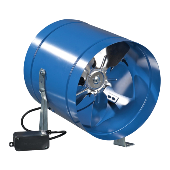
INDUSTRIAL ELECTRIC AXIAL FANS
VKOM 150
VKOM 200
VKOM 250
VKOM 315
INSTALLATION
Pencil
(Ø 8 mm for VKOM 150,200,250)
Vents-US
400 Murray Road, Cincinnati, OH 45217, USA
Tel: 1-888-640-0925, 513-583-5786, Fax: 513-268-4597
E-mail: support@ventsus.com
www.vents-us.com
Drill
(Ø 10mm for VKOM 315)
Tools required
Screwdriver
(NTS 8/50 for VKOM 150,200,250)
(NTS 10/60 VKOM 315)
Dowel
for VKOM 150,200,250)
(8,0x60 mm for VKOM 315)
Screws
(5,0x50 mm
MIU_19EN-01
Advertisement
Table of Contents

Related Manuals for Vents-us VKOM 150


Summary of Contents for Vents-us VKOM 150
- Page 1 VKOM 315 INSTALLATION Tools required Pencil Drill Screwdriver Dowel Screws (Ø 8 mm for VKOM 150,200,250) (NTS 8/50 for VKOM 150,200,250) (5,0x50 mm for VKOM 150,200,250) (Ø 10mm for VKOM 315) (NTS 10/60 VKOM 315) (8,0x60 mm for VKOM 315) Vents-US...
- Page 2 The protection trip current must be consistent with the current consumption of the fan. The fans are connected to the power mains in accordance with the applicable wiring diagram. Connection fans with single-phase motors to AC mains ~120 V 50/60 Hz Vents-US 400 Murray Road, Cincinnati, OH 45217, USA Tel: 1-888-640-0925, 513-583-5786, Fax: 513-268-4597 MIU_19EN-01 E-mail: support@ventsus.com...
- Page 3 2) Remove the cover from the terminal block. Remove the cable clamp. 3) Connect the cables according to the wiring diagram. 4) Install the terminal block cover Vents-US 400 Murray Road, Cincinnati, OH 45217, USA Tel: 1-888-640-0925, 513-583-5786, Fax: 513-268-4597 MIU_19EN-01 E-mail: support@ventsus.com...
- Page 4 Vents-US 400 Murray Road, Cincinnati, OH 45217, USA Tel: 1-888-640-0925, 513-583-5786, Fax: 513-268-4597 MIU_19EN-01 E-mail: support@ventsus.com www.vents-us.com...
Need help?
Do you have a question about the VKOM 150 and is the answer not in the manual?
Questions and answers