
Related Manuals for Vents-us CBF 110


Summary of Contents for Vents-us CBF 110
- Page 1 USER’S MANUAL CBF 110/130 CBF 110/130 T/TH/TP CBF 110/130 LIGHT CBF 110/130 LIGHT T/TH/TP Centrifugal ceiling fan...
-
Page 2: Table Of Contents
Disconnect the unit from power mains prior • Unpack the unit with care. to any installation operations. • While installing the unit, follow the safety • The unit must be grounded! regulations specific to the use of electric tools. vents-us.com... - Page 3 Do not sit on the unit and avoid placing • Use the unit only for its intended purpose. foreign objects on it. THE PRODUCT MUST BE DISPOSED SEPARATELY AT THE END OF ITS SERVICE LIFE. DO NOT DISPOSE THE UNIT AS UNSORTED MUNICIPAL WASTE. vents-us.com...
-
Page 4: Purpose
The unit is rated for continuous operation. Transported air must not contain any flammable or explosive mixtures, evaporation of chemicals, sticky substances, fibrous materials, coarse dust, soot and oil particles or environments favourable for the formation of hazardous substances (toxic substances, dust, pathogenic germs). vents-us.com... -
Page 5: Delivery Set
Additional options T : timer TH : humidity sensor and timer TP : motion sensor and timer Basic options _ : no integrated light Light : integrated LED light Rated air capacity (CFM) Fan series Ceileo : centrifugal ceiling fan vents-us.com... -
Page 6: Technical Data
The unit design is constantly being improved, so some models may be slightly different from those ones described in this manual. OVERALL AND CONNECTION DIMENSIONS OF THE FANS CBF 110/130 CBF 110/130 T/TH/TP CBF 110/130 Light CBF 110/130 Light T/TH/TP DIMENSIONS, inch MODEL Ceileo 110/130 ”... -
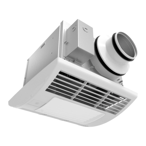
Page 7: Design And Operating Principle
CBF 110/130 DC T/TH/TP Exhaust spigot Backdraft damper Terminal box Casing Decorative grille Protective cap / sensor panel Control unit CBF 110/130 DC LIGHT T/TH/TP Exhaust spigot Backdraft damper Terminal box Casing Decorative grille Surface-mounted luminaire Protective cap / sensor panel... - Page 8 If the indoor humidity exceeds the set humidity point adjustable from 50 % up to 90 %, the fan either turns on or goes to the higher speed. After indoor humidity drops down the fan keeps running for a set turn-off delay time, adjustable from 1 to 90 minutes and the reverts to the initial operation status. vents-us.com...
-
Page 9: Mounting And Set-Up
While mounting the fan sufficient service access for maintenance or repair operations must be provided. The minimum gap between the fan and the ceiling is 5 mm ( ”). L = min 5 mm ") L = min 5 mm ") vents-us.com... - Page 10 Connection socket of the humidity sensor Connection socket Connection socket of the humidity sensor of the motion sensor Connection socket of the motion sensor 4. Install the decorative grille on the fan casing using the holders on the casing. vents-us.com...
- Page 11 BASIC FAN INSTALLATION OPTIONS Installation Side fixation Fixation between between the ceiling joists to one of the ceiling joists the ceiling joists using the mounting brackets Additional fastening holes in the fan casing may be used for mounting purposes vents-us.com...
-
Page 12: Connection To Power Mains
ACCESS TO THE TERMINAL BOX FOR WIRING THE FAN Remove the decorative grille. Remove the protective cap and install the cable gland. For accessing the connection terminals loosen the screw on the terminal box lid and take the lid off. vents-us.com... - Page 13 — turn-on delay timer adjustable from 0 to 180 seconds with the increment of 10 seconds (default setting 0). — humidity set point adjustable from 50 % up to 90 % (default setting 75 %). — access to submenu of the fan operation mode. vents-us.com...
-
Page 14: Maintenance
ANY MAINTENANCE OPERATIONS! The fan maintenance includes regular cleaning of the surfaces of dust and dirt. Replace the filter as required, but at least every 6 months. The impeller cleaning is shown below. Clean the impeller blades thoroughly every 6 months. vents-us.com... - Page 15 Make sure that the air ducts are not Low air flow. impeller is clogged. The air ducts are damaged. Make sure that the air dampers and louvre shutters damaged. The air dampers are closed. are open. vents-us.com...
-
Page 16: Storage And Transportation Regulations
The unit mustcan be transported only in the working position. • Avoid sharp blows, scratches, or rough handling during loading and unloading. • Prior to the initial power-up after transportation at low temperatures allow the unit to warm up at room temperature for at least 3-4 hours. vents-us.com... -
Page 17: Manufacturer's Warranty
If proof of sales date is absent, warranty period is calculated from the production date. The unit can be exchanged at the following address: Bodor Vents, LLC DBA: VENTS-US 11013 Kenwood Road Cincinnati, Ohio 45242 Phone: (513)348-3853 e-mail: sales@ventsus.com... -
Page 18: Seller Information
The unit has been installed in accordance with the provisions of all the applicable local and national construction, electrical and technical codes and standards. The unit operates normally as intended by the manufacturer. Signature: WARRANTY CARD Unit Type Centrifugal ceiling extract fan Model CBF _______________________ Serial Number Manufacture Date Purchase Date Warranty Period Seller Seller’s Stamp vents-us.com... - Page 19 vents-us.com...
- Page 20 VUSA166-1EN-01...
Need help?
Do you have a question about the CBF 110 and is the answer not in the manual?
Questions and answers