Finn HydroSeeder T30 Parts And Operator's Manual
Hide thumbs
Also See for HydroSeeder T30:
- Operator instructions and parts manual (73 pages) ,
- Parts and operator's manual (39 pages) ,
- Practical service manual for the parts professional (51 pages)

Related Manuals for Finn HydroSeeder T30


Summary of Contents for Finn HydroSeeder T30
- Page 1 Activate Your Warranty By Registering TODAY!!! 9281 LeSaint Drive • Fairfield, Ohio 45014 Phone (513) 874-2818 • Fax (513) 874-2914 ® T30 HydroSeeder Parts and Operator’s Manual Model SU Serial No. LBT30-SU Rev. A...
- Page 2 NOTES...
- Page 3 ▪ Return the part(s) and the completed Warranty Claim Form to Finn Corporation using the return shipping label. (Within 2 weeks) ▪ Tape the Orange identifier sheet, marked with the W / RMA# on the outside of the box you are shipping the defective part(s) to Finn in.
- Page 4 (except those referred to herein) that are manufac- dealers, or any other party. tured by Finn to be free from defects in material and workmanship 5. This Warranty does NOT cover any costs associated with trans- for a period of 12 months from date of purchase or 1200 hours of use, whichever comes first.
-
Page 5: Table Of Contents
Controls..........36-37 Continued . . . ® Hydroseeder is a registered trademark of the Finn Corporation... - Page 6 INDEX CONTINUED Hydraulic Oil Reservoir....... . 38-39 Hydraulic Pump Drive Assembly ......40-41 Hydraulic System .
-
Page 7: Safety First
SAFETY FIRST With any piece of equipment, new or used, the most important part of its operation is SAFETY! Finn Corporation encourages you and your employees to familiarize yourselves with your new equipment and to stress safe operation. The first six pages of this manual are a summary of all the main safety aspects associated with this unit. -
Page 8: Safety Summary Section
The FINN HydroSeeder ® is designed to mix and apply water, seed, fertilizer, agricultural lime and hydraulic mulch to the prepared seedbed. The resultant slurry from mixing one or more of the above materials may react causing harmful or deadly gasses within the tank. - Page 9 5. The T-30 HydroSeeder ® is a non-platform machine. 5. Plan application so that the furthest area is covered The discharge operator is positioned at the end of the first; working back toward the HydroSeeder®, so that discharge hose; not on the towing or carrying vehicle. the individuals are not walking back over slippery ground.
- Page 10 Severe bodily injury could Collect all fluids and dispose of them properly. result. 8. It is recommended that only authorized genuine FINN 5. On trailer units perform general maintenance such as replacement parts be used on the machine. checking the safety chains, hitch and hitch bolts, tires, 9.
- Page 11 CURRENT SET OF SAFETY DECALS DA NG E R DANGER E L E C T R O C U T I O N CONFINED SPACE HAZARD! (Reference: OSHA 29 CFR 1910.146) H A Z A R D ! Before entering tank: 1.
-
Page 12: Definition Of Hydroseeding
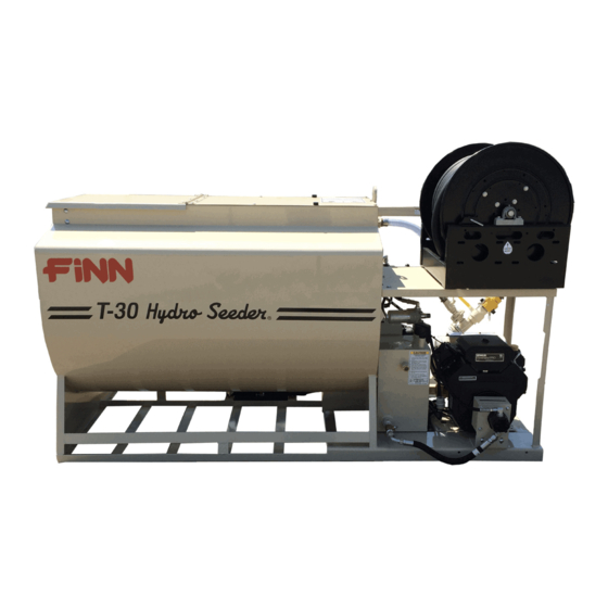
FINN T30 HYDROSEEDER This manual gives you step by step instructions for the operation and maintenance of the Finn HydroSeeder ® . For best results and to insure longer life of the equipment, please follow the instructions carefully. For your safety read the entire manual before operation of this unit. -
Page 13: Attachments
Place hard wood spacers along the length of truck rails or use Finn spring mounting kit (#011562) or equivalent. When using a truck with a tilt bed be sure to chain the truck bed down IMPORTANT: to prevent the bed from being accidentally hoisted. -
Page 14: Pre Start Check
- if not, lubricant must be replaced by the following procedure: a) Turn thumb nut clockwise until stem rises to maximum height. b) Remove cap and fill cap with sodium (water soluble) base grease. (FINN part number 000698). Do not use lithium base (chassis lube) grease. c) Replace cap. -
Page 15: Valve Operation
VALVE OPERATION: The base HydroSeeder ® is equipped with three (3) independently operated ball valves to control slurry flow (see Fig. 2). The first valve is the recirculation valve. An open recirculation valve allows flow back into the tank. The second valve is the pump discharge valve. An open pump discharge valve allows slurry to flow through the discharge hose. -
Page 16: Starting Procedure
The following tables show loading versus coverage rates for the Finn T30. Table A shows rates for “one step” applications. The coverage area is determined by the fiber mulch capacity of the HydroSeeder ® , and the rate at which it is applied. - Page 17 TABLE A USING SEED, FERTILIzER AND MULCH Unit Amount of Material in Tank (pounds(kilograms)) Covrage Area Seed Fertilizer Mulch Sq. Ft. (Sq. m.) 28 lbs (13 kg) 32 lbs (15 kg) 120 lbs (54 kg) 3,485 (324) Above Table is based on 1,500 pounds of mulch, 400 pounds of fertilizer and 345 pounds of seed (8 pounds/1,000 square feet) per acre.
-
Page 18: Tank Capacity Chart
TANK CAPACITY CHART: BOTTOM FIGURE 3 T-30 Gallons in. (cm) from in. (cm) from (liters) bottom (1136) 6.25 (15.9) 32.75 (83.2) (1041) 8.75 (22.2) 30.25 (76.8) (946) (27.9) (71.1) (852) 13.5 (34.3) 25.5 (64.8) (757) (40.6) (58.4) (662) 18.25 (46.4) 20.75 (52.7) (568) -
Page 19: Loading
LOADING: CAUTION: Take care not to lose pens, lighters, etc. from shirt pockets or drop pieces of paper or plastic bags into the tank, as these might plug the slurry system. 1. With clutch disengaged (off) and agitator control in the neutral position, start engine and allow it to warm up (See "Starting Procedure"... -
Page 20: Prior To Application
CAUTION: Hydraulic system will overheat if agitator shaft is jammed for extended period. This will damage hydraulic oil and system com- ponents. C. Fertilizer - Cut the fertilizer bag and dump the contents into the slurry tank. D. All other additives - Consult with manufacturer for proper loading technique. 7. -
Page 21: Application Of Slurry
APPLICATION OF SLURRY: I. GENERAL APPLICATION TECHNIQUES DANGER: Do not spray toward power lines, transformers or other high volt- age conductors. CAUTION: The driver of the carrying vehicle should remain alert for hazards to the operator, such as low power lines, hanging branches, etc. Driver should never start or stop abruptly. -
Page 22: Reloading
3. With the engine at ¾ speed, open the remote valve at the end of the hose to discharge the load. 4. When finished spraying, close the remote valve, disengage (turn off) the clutch, and stop the engine. If using fiber mulch, retain as much water as possible in the hose by elevating the ends or by coupling the ends together. -
Page 23: Hydraulic System
11. Add fuel stabilizer to fuel tank. HYDRAULIC SYSTEM: The hydraulic system on your Finn HydroSeeder ® is designed to give trouble free service, when properly main- tained. The most important areas of maintenance are the hydraulic oil and filtration. The reservoir holds 6 gal- lons of ISO Grade 46 Hydraulic Oil. -
Page 24: Lubrication Chart
LUBRICATION AND FLUIDS CHART Ref. No. Location Lubricant Frequency Number Check Grease Level in Pressure Lubricator Daily Grease Agitator Shaft Bearings Daily Check Engine Oil Level Daily Change Engine Oil and Filter See Engine Manual Grease Pump Bearings Weekly Check Hydraulic Fluid Level Weekly Change Hydraulic Fluid and Filter Seasonally... -
Page 25: Pump Maintenance
Suction Cover Bolt Clutch Retainer Suction Cover Washer 8 Locking Bolt Radial Lip Seal Lock Washer Casing Bearing Clutch Bearing Bolt Clutch Spacer Bearing Washer Pump Frame Frame Bearing Casing Drain Plug See parts manual for Finn part number NOTE:... - Page 26 A. FACTORY-TOLERANCES 1. To check pump tolerances loosen the two clamps on the pump suction piping and remove the inlet elbow. Through the pump suction hole, insert a feeler gauge between the pump impeller (3) and the suction cover (1). This measurement on a new pump is 0.030-0.045 inches (0.762 -1.15 mm). B.
-
Page 27: Trouble Shooting The Hydroseeder
D. INSTALLING NEW SEAL ASSEMBLY (#4) (DO NOT UNWRAP THE NEW SEAL ASSEMBLY UNTIL YOU ARE READY TO INSTALL. ALL PARTS OF THE ASSEMBLY ARE PACKED IN SEQUENCE OF INSTALLATION.) 1. To replace the seal assembly (4), perform the above operations under cleaning and remove pump casing (5) by removing the four bolts (7B) holding the casing and the casing bearing (7) to the pump frame (15). - Page 28 Sometimes when a stoppage occurs, you will not be able to find anything in the line. When this happens, it means the system became airbound instead of plugged. To remedy this, see “Foaming”. Plugging can occur in any 1 of 4 places; the valve and recirculation nozzle, the discharge nozzle, the pump area and the sump area.
- Page 29 ® TROUBLE SHOOTING YOUR HYDROSEEDER Problem Probable Causes Suggested Solutions LEAKS: Tank bearing Lack of lubrication - Replace seal and follow lube leaks. seal worn. Schedule. Bolts not tightened Tighten uniformly to 25 ft. lbs. properly. Pressure Clamps. Rubber seal cracked, Replace, always grease seal pinched or torn.
- Page 30 ® TROUBLE SHOOTING YOUR HYDROSEEDER Problem Probable Causes Suggested Solutions MACHINE JUMPS DURING OPERATION: Agitator. Agitator bent by heavy Straighten agitator or shim, so it object falling on it. runs true. Bent Paddles. Loading fiber mulch Straighten agitator paddle, realign into tank before tank is agitator to run true.
- Page 31 ® TROUBLE SHOOTING YOUR HYDROSEEDER Problem Probable Causes Suggested Solutions Constant plugging Incorrect loading procedure. Review loading procedure, pages during loading and 13-14. discharging. Improper operation by Reinstruct your operator. (Review operator. Operator’s Manual). Not moving valve handle Valve should be fully open. far enough.
-
Page 32: Notes
NOTES... -
Page 33: Parts Section
Hydroseeder ® Parts Manual Model SU... - Page 34 WHEN ORDERING PARTS, BE SURE TO STATE SERIAL NUMBER OF MACHINE...
-
Page 35: Agitator & Bearing Assembly
AGITATOR & BEARING ASSEMBLY Ref. No. Part Number Description No. Req'd REF. ONLY M12 Hex Nut REF. ONLY M12 Flat Washer REF. ONLY M12 Spring Washer 085161-01 Rear Bearing Assembly (Includes Items #5-9 & 10A) 085161-02 Front Bearing Assembly (Includes Items #5-9 & 10B) 007211 Flangette With Lube Coupling 003022... - Page 36 WHEN ORDERING PARTS, BE SURE TO STATE SERIAL NUMBER OF MACHINE...
-
Page 37: Hydraulic Agitator Drive
HYDRAULIC AGITATOR DRIVE Ref. No. Part Number Description No. Req'd 080482 Hydraulic Motor T30.6.5-01 Torque Arrestor Plate T30.6.5.2-00 Motor Shield 080523 Rigid Coupling REF. ONLY M6 X 15MM Socket Head Cap Bolt REF. ONLY M12 Hex Nut REF. ONLY M12 Spring Washer REF. - Page 38 WHEN ORDERING PARTS, BE SURE TO STATE SERIAL NUMBER OF MACHINE...
-
Page 39: Clutch Assembly
CLUTCH ASSEMBLY Ref. No. Part Number Description No. Req'd CHSF107.2 Clutch Assembly SF107.2.4 Clutch Casing 1 per SF107.2-2 Coil Mount 1 per SF107.2-1 Spacer 1 per SF107.2-3 Spacer 1 per SF23.2 Clutch 1 per SF107.2-9 Retainer Ring 1 per SF107.2-10 Bolt 1 per REF. - Page 40 WHEN ORDERING PARTS, BE SURE TO STATE SERIAL NUMBER OF MACHINE...
-
Page 41: Common Loose Parts
COMMON LOOSE PARTS Ref. No. Part Number Description No. Req'd REF. ONLY M5 X 10MM Bolt REF. ONLY M5 Spring Washer REF. ONLY M5 Flat Washer 004593 Drain Plug REF. ONLY M6 Hex Nut REF. ONLY M6 Spring Washer REF. ONLY M6 X 15MM Bolt 020886 Switch Button... - Page 42 WHEN ORDERING PARTS, BE SURE TO STATE SERIAL NUMBER OF MACHINE...
-
Page 43: Controls
CONTROLS Ref. No. Part Number Description No. Req'd 085142 Throttle Cable REF. ONLY M5 X 15MM Round Head Bolt REF. ONLY M5 Flat Washer REF. ONLY M5 Spring Washer REF. ONLY M5 Hex Nut REF. ONLY M5 X 40 MM Socket Head Bolt REF. - Page 44 WHEN ORDERING PARTS, BE SURE TO STATE SERIAL NUMBER OF MACHINE...
-
Page 45: Hydraulic Oil Reservoir
HYDRAULIC OIL RESERVOIR Ref. No. Part Number Description No. Req'd SF09-04 Sight Gauge SF09-06 Washer SF09-02 Flat Washer REF. ONLY M4 X 10MM Socket Head Bolt CHEF25 Filter Breather Cap T30.7.1-00 Hydraulic Reservoir CHCU40X100 Suction Strainer SF09-09 Flange T30.7-02 Flange 020658 Ball Valve M12X1.5/3/4"... - Page 46 WHEN ORDERING PARTS, BE SURE TO STATE SERIAL NUMBER OF MACHINE...
-
Page 47: Hydraulic Pump Drive Assembly
HYDRAULIC PUMP DRIVE ASSEMBLY Ref. No. Part Number Description No. Req'd REF. ONLY M10 X 30MM Hex Head Bolt 080642 Hydraulic Pump REF. ONLY M10 Spring Washer REF. ONLY M10 Hex Nut REF. ONLY M6 X 6MM Socket Set Screw 080647 Coupling Half - 5/8"... - Page 48 WHEN ORDERING PARTS, BE SURE TO STATE SERIAL NUMBER OF MACHINE...
-
Page 49: Hydraulic System
HYDRAULIC SYSTEM Ref. No. Part Number Description No. Req'd 085232-01 Suction Hose 012087 Adapter 080642 Hydraulic Pump 085235 Adapter 085232-03 Pressure Hose FW71784 075552 Adapter 012044 Pressure Gauge 085235 Adapter 085232-04 Motor Hose 085232-05 Motor Hose 080743 Hydraulic Valve 055359 Adapter 085232-02 Return Hose... - Page 50 WHEN ORDERING PARTS, BE SURE TO STATE SERIAL NUMBER OF MACHINE...
-
Page 51: Pump Assembly
PUMP ASSEMBLY Ref. No. Part Number Description No. Req'd REF. ONLY M12 X 40MM Hex Head Bolt REF. ONLY M12 Flat Washer CHSF24.1B-02 Suction Cover CH220X5.7 GB1235-76 O-Ring CHSF24.1B-03 Impeller CHBIA-32 Mechanical Seal CHSF24.1-01 Pump Casing 085234 Lubricator Adapter 002383 Pressure Lubricator CHFB32X45X8 GB/T13871-92 Radial Lip Seal REF. - Page 52 WHEN ORDERING PARTS, BE SURE TO STATE SERIAL NUMBER OF MACHINE...
-
Page 53: Tank Top Assembly
TANK TOP ASSEMBLY Ref. No. Part Number Description No. Req'd T30.2-01 Tank Top Lid SF26.2 Bumper REF. ONLY M8 Hex Nut REF. ONLY M8 X 25MM Hex Head Bolt REF. ONLY M8 Flat Washer REF. ONLY M8 Spring Washer REF. ONLY M8 Hex Nut Ø8X80GB/T119-1986 Pin Ø8X80GB/T119-1986... - Page 54 WHEN ORDERING PARTS, BE SURE TO STATE SERIAL NUMBER OF MACHINE...
-
Page 55: Pump, Piping & Discharge Assembly
PUMP, PIPING & DISCHARGE ASSEMBLY Ref. No. Part Number Description No. Req'd 080366 Pipe Clamp REF. ONLY M12 X 70 MM Round Head Bolt SF20.6-1 Pipe Clamp Seal REF. ONLY M12 Flat Washer REF. ONLY M12 Hex Nut T30.5.1-00 90° Discharge Elbow T30.5.2-00 Suction Pipe REF. - Page 56 VIEW D VIEW C (Both Sides) (Both Sides) VIEW B (Both Sides) VIEW A *NOTE: These Items Are Not Included in the T30 Decal Kit (080699) and MUST Be Ordered Separately. VIEW A VIEW E WHEN ORDERING PARTS, BE SURE TO STATE SERIAL NUMBER OF MACHINE...
-
Page 57: Decals
"WARNING! Sever & Flying Debris Hazards" Decal 1 per 012180 "CAUTION. To Avoid Damage To Suction Cover ..." Decal 1 per 031235** "FINN" Decal (Medium Red) 085158** "T30 HydroSeeder" Decal 011690** FINN Name Plate 012260** "Important - Maintain All Safety Decals ... " Metal Plate NOTES: All of the decals shown on Page 48 are shown for location purposes ONLY. - Page 58 WHEN ORDERING PARTS, BE SURE TO STATE SERIAL NUMBER OF MACHINE...
-
Page 59: Hose Reel Assembly
HOSE REEL ASSEMBLY Ref. No. Part Number Description No. Req'd 326250-23X11X2.5 23 X 11.25 X 2.5 X 14 Ga. Head 326250-23X11X0.94 23 X 11.25 X 0.94 X 14 Ga. Head 326100-20X11 Drum 366150P-23X20 Frame Weldment Assembly 326460P-19.5 Drum Shaft 326489P-20 Threaded Rod 326486 3/4"... -
Page 60: Control Panel Wiring
CONTROL PANEL WIRING GROUND WIRE SHUT OFF START ACCESSORIES GENERATOR MAIN LIVE WIRE WHEN ORDERING PARTS, BE SURE TO STATE SERIAL NUMBER OF MACHINE... - Page 61 Narrow Ribbon Nozzle 080260 Nyglass Adapter 160750 Reducer Bushing 004593 Drain Plug 006515 Coupler Gasket 012681T Finn Beige Touch-Up Paint 012681A Finn Beige Aerosol Paint 080535 Remote Valve Assembly 012083 Full Port Ball Valve 080260 Male Nyglass Adapter 080261 Female Nyglass Coupler...
Need help?
Do you have a question about the HydroSeeder T30 and is the answer not in the manual?
Questions and answers