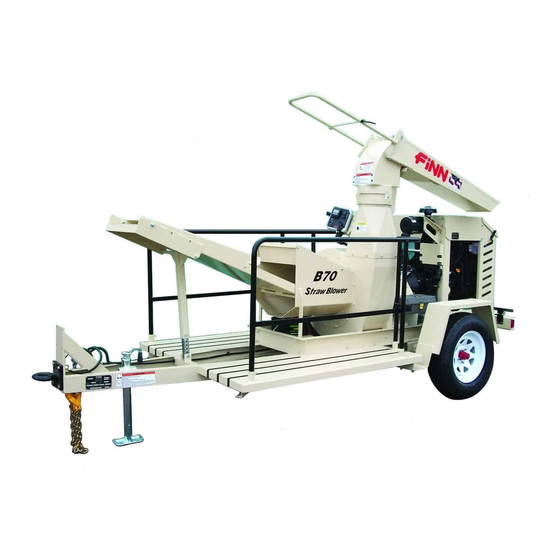
Finn B70 Operator Instructions And Parts Manual
Straw blower
Hide thumbs
Also See for B70:
- Parts and operator's manual (39 pages) ,
- Manual (38 pages) ,
- Technical bulletin (6 pages)
Table of Contents
Advertisement
Advertisement
Table of Contents

Related Manuals for Finn B70


Summary of Contents for Finn B70
- Page 1 Your Warranty Your Warranty By Registering By Registering TODAY!!! TODAY!!! 9281 LeSaint Drive • Fairfield, Ohio 45014 Phone (513) 874-2818 • Fax (513) 874-2914 1-800-543-7166 B70 Straw Blower Operator Instructions and Parts Manual Model ML Serial No. _____________ B70 ML0911...
- Page 3 IF FINN CORPORATION DOES NOT HAVE YOUR COMPLETED REGISTRATION FORM ON FILE, YOUR WARRANTY CLAIM WILL BE DENIED. Once your FINN equipment has been registered, your FINN Limited Warranty will be activated per the warranty statement on the next page.
- Page 4 Follow the instruction sheet, on property damage sustained by a person claiming to be a third party how to use your Finn Oil Analysis Kit that comes with the Kit. Failure beneficiary of a surviving warranty under the law of any jurisdiction.
-
Page 5: Table Of Contents
Definition Of Mulching ..........5 The Finn B70 Straw Blower and How It Works......5 Towing Vehicle. - Page 6 B70 Right Hand Decals ........
-
Page 7: Safety First
SAFETY FIRST With any piece of equipment, new or used, the most important part of its operation is SAFETY! FINN Corporation encourages you and your employees to familiarize yourselves with your new equipment and stresses safe operation. The first five pages of this manual are a summary of the main safety aspects associated with this unit. -
Page 8: Straw Blower Safety Summary Section
Above all, remember that safety is up to you. The FINN STRAW BLOWER is intended to be used as an applicator of vegetative hay or straw mulches onto the seedbed. Its use with other products or for other applications must be by approval of the product’s manufacturer. - Page 9 Collect all used fluids and dispose of them properly. It is recommended that only authorized, genuine FiNN replacement parts be used on the machine. Make certain that all decals on the machine are maintained in good legible condition. Replacement...
- Page 10 CURRENT SET OF SAFETY DECALS WARNING CAUTION RUNAWAY VEHICLE HAZARD! Always inspect tow vehicle and equipment hitch before towing. Wear ear protection when Tighten all hitch bolts and properly connect wiring and safety chains. operating machine. BREAKAWAY SWITCH DO NOT use for parking. The sound power level could Attach cable to towing vehicle with enough slack for turning.
-
Page 11: Introduction
TOWING VEHICLE: The truck used to tow the FINN B70 Straw Blower should have a bed large enough to carry the quantity of mulch needed for economical operation. The truck must be equipped with a ball or pintle type hitch to tow the Straw Blower. -
Page 12: Equipment Check
EQUIPMENT CHECK: Equipment check should be made with the engine OFF and all rotating parts stopped. Failure to comply could result in death or serious injury. 1. Tool kit - make sure that it contains all prescribed items (see tool kit list). 2. -
Page 13: Shutting Down The Engine
5. Turn the key clockwise to the START “ ” position. Release the key as soon as the engine starts. It will return to the ON position. If a fault condition exists, the engine ECU may prevent the engine from starting. All fault conditions will be indicated by the digital display. The display will indicate the active fault(s) by presenting a pop-up graphic describing the fault condition. -
Page 14: Blower Discharge
BLOWER DISCHARGE: The B70 Straw Blower should be towed to a point approximately 20 ft. (6 m) from the area where the mulch is to be applied. The operator should elevate the discharge spout to about 10 degrees above the plane of the seedbed so that the mulch floats onto the seedbed. -
Page 15: System Operation
SYSTEM OPERATION MENU NAVIGATION Engine Data Alarm Symbol Indicator The control unit has three navigation buttons which are configured as softkeys. The system softkeys are used to Engine navigate between displays, Data select menu items and change data. Pressing any of the three navigation buttons will Data display the softkey menu that is... -
Page 16: Main Menu Access
MAIN MENU ACCESS To access the Main Menu, press any of the three navigation buttons. The unit will display a softkey popup window defining the available navigation possibilities. Select the Main Menu using the center softkey as shown. MAIN MENU NAVIGATION Access the main menu using the center softkey. -
Page 17: Fault Codes
FAULT CODES Engine fault codes (active and stored) are generated by the engine ECU and communicated to the control panel. ACTIVE FAULT CODES The control system reads standard messages to indicate active fault codes. When a fault is active the control system activates a popup fault display containing a check engine icon, fault code number (if applicable),... -
Page 18: Stored Fault Codes
STORED FAULT CODES The control unit allows the operator to request any stored fault codes that may be contained in the engine ECU. To view stored faults select the “Fault Codes” menu selection from the main menu. The control system will send a request to the engine ECU for any faults that the ECU may have stored. -
Page 19: Resetting Maintenance Timer
RESETTING MAINTENANCE TIMER The maintenance timer is operator configurable and can be accessed through the engine settings menu. See “Reset MaintTimer” selection in engine settings menu. When the maintenance timer has expired, a pop-up alert window indicating that “Engine Maintenance is Due” will be displayed. -
Page 20: Contrast Setting
CONTRAST SETTING The LCD contrast is adjustable from 0 to 100%. To adjust the LCD contrast enter the Main Menu and navigate to the “Display Setup” menu using the “ ” softkey. When highlighted enter the Display Setup menu by selecting the “... -
Page 21: Display Mode Setting
DISPLAY MODE SETTING Two display formats are available: “Single” display and “Dual” display formats. To access the display format setting, enter the Main Menu. Navigate to the “Display Setup” menu entry using “ ” softkey. When highlighted, enter the Display Setup menu by selecting the “... -
Page 22: Engineering Units
ENGINEERING UNITS Displayed engineering units can be configured for Pressure, Temperature and Volume. To access the engineering unit’s settings, enter the Main Menu. Navigate to the “Display Setup” menu entry using “ ” softkey. When highlighted enter the Display Setup menu by selecting the “... -
Page 23: Display List
DISPLAY LIST SINGLE DATA FORMAT DUAL DATA FORMAT... -
Page 24: About Menu
MISCELLANEOUS DISPLAYS ABOUT MENU The About Menu indicates the software information used for programming the control unit. ENGINE SETTINGS The Engine Settings are factory-specified. This feature is password-protected to ensure the correct use of the engine in this unit. -
Page 25: Regeneration
REGENERATION See Engine Owner’s Manual for information on the Diesel Particulate Filter (DPF). Particulate Matter (PM) in the engine exhaust accumulates in the Soot Filter (SF) within the DPF causing it to clog, reducing engine performance. Therefore, it is necessary to burn off the accumulated PM. -
Page 26: Reset Regeneration Operation - Displays
RESET REGENERATION NORMAL OPERATION - DISPLAYS The engine control panel is set at the factory to allow Reset Regeneration to occur automatically. However, the operator has the option to inhibit Reset Regeneration via the control panel [Main Menu “ ” Regeneration “... -
Page 27: Reset Regeneration Standby Due To Inhibit Switch
RESET REGENERATION STANDBY DUE TO INHIBIT SWITCH During machine operation with Regeneration in the Inhibit state on the control panel, a notification and regeneration inhibited icon will display at the bottom of the screen. If the ECU determines that Reset Regeneration is required, a Auto Regeneration request will be displayed. If the operator allows the regeneration, it will begin and a notification and regeneration icon will display at the bottom of the screen. -
Page 28: Reset Regeneration Standby Due To Low Doc Temperature
RESET REGENERATION STANDBY DUE TO LOW DOC TEMPERATURE For Reset Regeneration to begin, the DOC temperature has to be at a sufficient level. If the DOC has not reached this temperature and Reset Regeneration is required, then a notification to Increase RPM / Load and the Regeneration icon will be displayed. - Page 29 Note: Stationary Regeneration will not begin if any of the following conditions are present: Coolant temperature is less than 60° C (140° F) The engine has not been running for 15 minutes An important DTC is active The interlock switch is off (PTO clutch is engaged) Idle speed is too high If these conditions are present, a notification will be displayed.
-
Page 30: Manual Stationary Regeneration - Operator Request
STATIONARY REGENERATION BY ENGINE MANAGEMENT (CONTINUED) If the Stationary Regeneration is delayed by pressing the right soft key marked “NO” when the request is displayed, a 15% power reduction is immediately applied to the engine. A notification stating that “If no stationary performed within 2 hours, Power Reduction is 50%”... - Page 31 MANUAL STATIONARY REGENERATION - OPERATOR REQUEST (CONTINUED) 4. At this point, the ECU will take over control of the engine to perform the Stationary Regeneration and a notification of “Stationary Active” and the regeneration icon will be display along with a status bar (0 to 35 minutes) at the bottom of the screen. Note: When the Stationary Regeneration starts, the engine speed increases gradually to high idle speed, then the regeneration begins and may modulate engine speed throughout the process.
-
Page 32: Recovery Regeneration
RECOVERY REGENERATION If Recovery Regeneration is not performed within the allowed 10 hours, the engine will go into Limp Home Mode and a DTC will be displayed. There are only two ways out of Limp Home Mode, perform a Recovery Regeneration or perform a SF exchange at a Yanmar certified service center. - Page 33 RECOVERY REGENERATION (CONTINUED) Note: Recovery Regeneration will not begin if any of the following conditions are present: Coolant temperature is less than 60° C (140° F) The engine has not been running for 15 minutes An important DTC is active The interlock switch is off (PTO clutch is engaged) Idle speed is too high If these conditions are present, a notification will be displayed.
-
Page 34: Cleaning And Maintenance
CLEANING AND MAINTENANCE: Before servicing the machine, turn off engine and allow all moving parts to stop. Disconnect the battery cables to prevent accidental starting of the machine. Tag the engine operating area to show that the machine is being serviced. Use lockout/ tagout procedure (29 CFR 1910.147). -
Page 35: Lubrication And Fluids Chart
LUBRICATION AND FLUIDS CHART Ref. No. Location Lubricant Frequency Number Grease drive shaft bearings. Weekly Repack wheel bearings. Annually Check engine oil level. Daily Check air cleaner. Daily Change engine oil and filter. See Engine Manual Grease PTO release bearing. Daily Grease PTO main shaft bearing. -
Page 36: Clutch Care And Maintenance
CLUTCH CARE AND MAINTENANCE: This is an outline of the PTO clutch adjustment and lubrication procedure. When you perform maintenance beyond this outline, refer to the power take-off manufacturer's service manual. In order to properly identify parts when ordering replacement parts, always refer to the unit and specification number stamped on the nameplate located on the top center of the power take-off housing. -
Page 37: Coupling Maintenance
COUPLING MAINTENANCE: Coupling alignment should be checked seasonally or every 500 hours. 1. Remove coupling guard. 2. Check parallel alignment by placing a straight-edge across the two coupling flanges and measuring the maximum offset at various points around the periphery of the coupling without rotating the coupling. -
Page 38: Technical Specifications
FINN B70 Straw Blower TECHNICAL SPECIFICATIONS POWER ..........Yanmar 3TNV88C-DYEM, 35.1hp (26.2kW), 3 cylinder water cooled diesel engine. Tier 4Final. 1.642 L ENGINE SAFETY SYSTEM ....Low oil pressure, Electronic engine control and monitoring CAPACITY ..........Up to 7 tons of hay or straw per hour FUEL TANK CAPACITY ......11 gallon (41.6 L) -
Page 39: Parts Section
Straw Blower Parts Manual Model ML... - Page 40 18 17 15 14 WHEN ORDERING PARTS, BE SURE TO STATE SERIAL NUMBER OF MACHINE...
-
Page 41: Discharge Assembly
DISCHARGE ASSEMBLY Ref. No. Part Number Description No. Req’d 031247 Transition Assembly Hex Head Cap Screw, 3/8 - 16 UNC - 1 LG. Grade 5 Plain Washer, 3/8 Regular Type B Prevailing Torque Hex Nut, 3/8 All Metal Type Hex Head Cap Screw, 1/2 - 13 UNC - 1.75 LG. Grade 5 Plain Washer, 1/2 Narrow Type A Prevailing Torque Hex Nut, 1/2 All Metal Type Hex Head Cap Screw, 3/8 - 16 UNC - 1.25 LG. - Page 42 DISCHARGE ASSEMBLY Ref. No. Part Number Description No. Req’d 031338-10 Top Seal Retaining Plate 031338-09 Top Seal 031243-08 Elbow Hinge Rod 031338-11 Hinge Seal Keps Nut, No. 10 - 24 Slotted Flat Head Machine Screw, No. 10 - 24 x 0.625 LG. Slotted Round Head Machine Screw, No.
- Page 43 THIS PAGE LEFT BLANK INTENTIONALLY WHEN ORDERING PARTS, BE SURE TO STATE SERIAL NUMBER OF MACHINE...
-
Page 44: Shredder Box And Feed Chute (Standard Trailer Model)
WHEN ORDERING PARTS, BE SURE TO STATE SERIAL NUMBER OF MACHINE... - Page 45 SHREDDER BOX AND FEED CHUTE (STANDARD TRAILER MODEL) Ref. No. Part Number Description No. Req’d Hex Head Cap Screw, 1/2 - 13 UNC - 1.5 LG. Grade 5 Plain Washer, 5/16 Regular Type B Plain Washer, 1/2 Narrow Type A Hex Head Cap Screw, 5/16 - 18 UNC - 0.875 LG.
-
Page 46: Shredder Box And Feed Chute (Standard Skid Model)
UNDERSIDE DETAIL WHEN ORDERING PARTS, BE SURE TO STATE SERIAL NUMBER OF MACHINE... - Page 47 SHREDDER BOX AND FEED CHUTE (STANDARD SKID MODEL) Ref. No. Part Number Description No. Req’d Hex Head Cap Screw, 1/2 - 13 UNC - 1.5 LG. Grade 5 031184-06 Lower Feed Chute Stand 031095-01 Jack Mounting Weldment Plain Washer, 5/16 Regular Type B Plain Washer, 1/2 Narrow Type A Hex Head Cap Screw, 5/16 - 18 UNC - 0.875 LG.
-
Page 48: Shredder Box And Feed Chute (R-H Model)
WHEN ORDERING PARTS, BE SURE TO STATE SERIAL NUMBER OF MACHINE... - Page 49 SHREDDER BOX AND FEED CHUTE (R-H MODEL) Ref. No. Part Number Description No. Req’d 031292 Shredder Box Weldment 031293 Feed Chute Weldment 031289-01 Feed Chute Cover 031294 Feed Chute Extension 031295-01 Door 031096-04 Hinge Pin 031295-04 Left Leg Weldment 031295-05 Right Leg Weldment Hex Head Cap Screw, 3/8 - 16 UNC - 1.25 LG.
-
Page 50: Trailer Frame Assembly (Standard Trailer Model)
TRAILER FRAME ASSEMBLY (STANDARD TRAILER MODEL) Ref. No. Part Number Description No. Req’d 004996 Pipe Plug 031183-02 Left Guard Rail Weldment 031183-01 Right Guard Rail Weldment Square Head Set Screw, 3/8 - 16 UNC - 1.0 LG. Flat Point Hex Nut, 3/8 - 16 Prevailing Torque Hex Nut, 3/8 All Metal Type Plain Washer, 3/8 Regular Type B Hex Head Cap Screw, 3/8 - 16 UNC - 1.25 LG. - Page 51 030482 2 inch Ball (optional) 080043 2-1/2 inch Lunette Eye (for Pintle Hitch) 031474 #3000 Rubber Torsion Axle B70 (See Trailer Wheel / Axle Assembly section for parts detail.) WHEN ORDERING PARTS, BE SURE TO STATE SERIAL NUMBER OF MACHINE...
-
Page 52: Trailer Harness: Grommets And Clamps (Standard Trailer Model)
TRAILER HARNESS: GROMMETS AND CLAMPS (STANDARD TRAILER MODEL) Ref. No. Part Number Description No. Req’d 004656 Rubber Grommet 060281 Loop Clamp Helical Spring Lock Washer, 1/4 Regular Hex Nut, 1/4 - 20 Standard Hardware Item - Available at your local hardware store. WHEN ORDERING PARTS, BE SURE TO STATE SERIAL NUMBER OF MACHINE... -
Page 53: Control Box Mount Assembly (Standard Trailer Model)
CONTROL BOX MOUNT ASSEMBLY (STANDARD TRAILER MODEL) Ref. No. Part Number Description No. Req’d Hex Nut, 3/8 - 16 Helical Spring Lock Washer, 3/8 Regular Plain Washer, 3/8 Regular Type B Prevailing Torque Hex Nut, 1/4 All Metal Type Plain Washer, 1/4 Regular Type B 031490-01 Control Box Mount Bracket Hex Head Cap Screw, 3/8 - 16 UNC - 1.0 LG. - Page 54 WHEN ORDERING PARTS, BE SURE TO STATE SERIAL NUMBER OF MACHINE...
-
Page 55: Control Box Mount And Lift Eye Assembly
CONTROL BOX MOUNT AND LIFT EYE ASSEMBLY (STANDARD R-H AND SKID MODELS) Ref. No. Part Number Description No. Req’d Hex Head Cap Screw, 3/8 - 16 UNC - 1.25 LG. Grade 5 Plain Washer, 3/8 Regular Type B Prevailing Torque Hex Nut, 3/8 All Metal Type 031393-01 Support Arm (left hand side) 031326-04... - Page 56 WHEN ORDERING PARTS, BE SURE TO STATE SERIAL NUMBER OF MACHINE...
-
Page 57: Control Box
CONTROL BOX Ref. No. Part Number Description No. Req’d 031515 Control Box Assembly 031520 Controller / Display 031507 SPDT Rocker Switch 020886 Horn Button 031506 Ignition Switch 031506-01 Replacement Key for Ignition Switch 031510 Control Box, Modified 031571 Control Box Back Panel 031511 Control Box Decal 031575... -
Page 58: Bumper Assembly (Standard Trailer Model)
WHEN ORDERING PARTS, BE SURE TO STATE SERIAL NUMBER OF MACHINE... - Page 59 BUMPER ASSEMBLY (STANDARD TRAILER MODELS) Ref. No. Part Number Description No. Req’d Hex Nut, 1/2 - 13 Helical Spring Lock Washer, 1/2 Regular Plain Washer, 1/2 Narrow Type A Hex Head Cap Screw, 1/4 - 20 UNC - 0.75 LG. Grade 5 Plain Washer, 1/4 Regular Type B 031269 Bumper...
- Page 60 FRONT / JACK AREA WHEN ORDERING PARTS, BE SURE TO STATE SERIAL NUMBER OF MACHINE...
-
Page 61: Hardware Assemblies For Electrical Components
HARDWARE ASSEMBLIES FOR ELECTRICAL COMPONENTS (STANDARD TRAILER MODELS) Ref. No. Part Number Description No. Req’d 031389 Tool Box 004719 Red Reflector Hex Head Cap Screw, 3/8 - 16 UNC - 1.0 LG. Grade 5 Plain Washer, 3/8 Regular Type B 008422 Loop Clamp Helical Spring Lock Washer, 3/8 Regular... -
Page 62: Trailer Wheel / Axle Assembly (Standard Trailer Model)
WHEN ORDERING PARTS, BE SURE TO STATE SERIAL NUMBER OF MACHINE... - Page 63 Brake Assembly, Left Side 005824-02 Brake Assembly, Right Side Hex Nut (included with part number 14) 031474 #3000 Rubber Torsion Axle B70 (includes all listed parts, Reference Numbers 1 - 16) 031475 Wheel / Tire Assembly (Not Shown) 031512 Wheel...
-
Page 64: Trailer Wiring
BROWN BROWN BROWN WHITE STARTER GROUND (WHITE) LEFT TURN RUNNING (YELLOW) BROWN BROWN LIGHTS (BROWN) BRAKES NOT USED (BLACK) RIGHT TURN (GREEN) Female Coupler Looking at Terminal End TRAILER WIRING Ref. No. Part Number Description No. Req’d 031210 Trailer Wiring Harness 075592 Trailer Plug 023424... -
Page 65: Blower And Drive
BLOWER AND DRIVE Ref. No. Part Number Description No. Req’d 031274 Coupling Insert 031272 Coupling Flange Hex Socket Set Screw, Cup Point, 5/16 - 18 x 0.7 190125 Key, 3/8 x 3/8 x 2 030904 Blower Shaft Hex Head Cap Screw, 3/4 - 10 UNC - 3 LG. Grade 5 Plain Washer, 3/4 Wide Type A Plain Washer, 3/4 Narrow Type B Prevailing Torque Hex Nut, 3/4 All Metal Type... - Page 66 TRAILER ASSEMBLY CLUTCH HANDLE WHEN ORDERING PARTS, BE SURE TO STATE SERIAL NUMBER OF MACHINE...
-
Page 67: Coupling Guard, Clutch Handle And Battery Assembly
COUPLING GUARD, CLUTCH HANDLE AND BATTERY ASSEMBLY Ref. No. Part Number Description No. Req’d 000427 Handle Grip, Black 031302 Clutch Lever (Skid and Right-hand Feed Models) 031144 Clutch Lever (Trailer Models Only) 031514 Coupling Guard Plain Washer, 1/4 Regular Type B Helical Spring Lock Washer, 1/4 Regular Hex Head Cap Screw, 1/4 - 20 UNC - 0.75 LG. - Page 68 WHEN ORDERING PARTS, BE SURE TO STATE SERIAL NUMBER OF MACHINE...
-
Page 69: Power Take Off Assembly
POWER TAKE OFF ASSEMBLY Ref. No. Part Number Description No. Req’d Bell Housing 100348 Nameplate 100224 Grease Fitting (Cross Shaft) Bolt 005151 Pilot Bearing 031219 Modified Clutch Lever 100043 Grease Fitting (Main Bearing) 100223 Drive Shaft 100060 Main Bearing 100059 Internal Snapring 100055 External Snapring... - Page 70 WHEN ORDERING PARTS, BE SURE TO STATE SERIAL NUMBER OF MACHINE...
-
Page 71: Clutch Assembly
CLUTCH ASSEMBLY Ref. No. Part Number Description No. Req’d 100333 Clutch Assembly (Includes Key Numbers 2 through 24) Clutch Body 100209 Facing Plate Pressure Plate Adjusting Ring Wear Plate for Adjusting Ring (not shown) 100211 Lever Spring Lever Clevis Pin Retaining Ring Lock Bolt Lock Washer... - Page 72 39 40 WHEN ORDERING PARTS, BE SURE TO STATE SERIAL NUMBER OF MACHINE...
-
Page 73: Engine Parts
ENGINE PARTS Ref. No. Ref. Part Number Description No. Req’d 031542 Overflow Bottle Assembly, 1 quart Hose Clamp, 24 - 44 mm Hex Flange Machine Screw, M8 - 16 x 1.25 LG 031534 Radiator Support, Upper 031538 Radiator Mount Isolator, Upper ... - Page 74 ENGINE PARTS Ref. No. Ref. Part Number Description No. Req’d 031522-00 Fuel / Water Separator Assembly 031522-01 Upper Body Housing Assembly 031522-02 O-ring 031522-03 Filter Element 031522-04 Float 031522-05 031522-06 Drain Plug 031521 Pump Assembly, Fuel Feed ECU (Supplied with Engine) 022450 Pipe Clamp 007391...
-
Page 75: Engine Oil Drain
ENGINE OIL DRAIN Ref. No. Part Number Description No. Req’d 031389 Tool Box 031553 Hose Assembly, Remote Oil Drain (RH and Skid Units Only) 6 - 32 x 5/8 Flat Countersunk Head Machine Screw (RH and Skid Units Only) 031423 Spring Clip Holder (RH and Skid Units Only) Plain Washer, #6 Regular Type B (RH and Skid Units Only) Prevailing Torque Hex Nut, #6 All Metal Type... - Page 76 WHEN ORDERING PARTS, BE SURE TO STATE SERIAL NUMBER OF MACHINE...
-
Page 77: Engine Peripheral Assembly
ENGINE PERIPHERAL ASSEMBLY Ref. No. Part Number Description No. Req’d 031482-00 Left Hand Engine Shroud Support Weldment 031483-00 Right Hand Engine Shroud Support Weldment Hex Nut, 1/4 - 20 Helical Spring Lock Washer, 1/4 Regular Plain Washer, 1/4 Regular Type B 031521 Pump Assembly, Fuel Feed 031522-00... - Page 78 WHEN ORDERING PARTS, BE SURE TO STATE SERIAL NUMBER OF MACHINE...
-
Page 79: Engine Sheetmetal Assembly
ENGINE SHEETMETAL ASSEMBLY Ref. No. Part Number Description No. Req’d 031485-00 Engine Shroud Access Door Assembly 031403 Radiator Screen 031487-00 Radiator Shroud Weldment 190260 Trim Seal, 5/8 Bulb x 1/8 Edge Thick 190259 Edge Trim, 7/16 Wide x 1/16 Edge Thick 190258 Trim Seal, 7/16 Bulb x 1/16 Edge Thick 006499... - Page 80 12 13 WHEN ORDERING PARTS, BE SURE TO STATE SERIAL NUMBER OF MACHINE...
-
Page 81: Regen Interlock Switch
REGEN INTERLOCK SWITCH Ref. No. Part Number Description No. Req’d 031489-00 Regen Interlock Bracket Helical Spring Lock Washer, M8 Hex Head Cap Screw, M8 x 1.25 - 16 Hex Head Cap Screw, 3/8 - 16 UNC - 1.25 LG. Grade 5 Plain Washer, 3/8 Regular Type B Cross Recessed Pan Head Screw, #6 - 32 - 5/8 031567-06... -
Page 82: Electrical
ELECTRICAL Ref. No. Part Number Description No. Req’d 031567-01 Engine Harness - Trailer Models 031567-02 Engine Harness - Skid Models 031567-03 Battery Ground Cable 031567-04 Starter Cable 031567-05 Frame Ground Cable 031567-06 Regeneration Interlock Switch Cable Assembly WHEN ORDERING PARTS, BE SURE TO STATE SERIAL NUMBER OF MACHINE... -
Page 83: Tool Kit
TOOL KIT Ref. No. Part Number Description No. Req’d 020057 #13 Twine Knife 020063 #11 Twine Knife Manual, Engine Manual, Parts and Operation WHEN ORDERING PARTS, BE SURE TO STATE SERIAL NUMBER OF MACHINE... - Page 84 11 12 WHEN ORDERING PARTS, BE SURE TO STATE SERIAL NUMBER OF MACHINE...
-
Page 85: B70 Trailer Decals
B70 Decal Kit NOTE: All of the decals listed here with a in the part number space are available only in the B70 Decal Kit. Replacement decals and plates for those identified with a part number are not part of the decal kit and must be ordered separately. - Page 86 WHEN ORDERING PARTS, BE SURE TO STATE SERIAL NUMBER OF MACHINE...
-
Page 87: B70 Skid Decals
B70 Decal Kit NOTE: All of the decals listed here with a in the part number space are available only in the B70 Decal Kit. Replacement decals and plates for those identified with a part number are not part of the decal kit and must be ordered separately. - Page 88 12 13 WHEN ORDERING PARTS, BE SURE TO STATE SERIAL NUMBER OF MACHINE...
-
Page 89: B70 Right Hand Decals
B70 Decal Kit NOTE: All of the decals listed here with a in the part number space are available only in the B70 Decal Kit. Replacement decals and plates for those identified with a part number are not part of the decal kit and must be ordered separately.
Need help?
Do you have a question about the B70 and is the answer not in the manual?
Questions and answers