Table of Contents
Advertisement
Quick Links
Advertisement
Table of Contents

Related Manuals for Finn MTS SR


Summary of Contents for Finn MTS SR
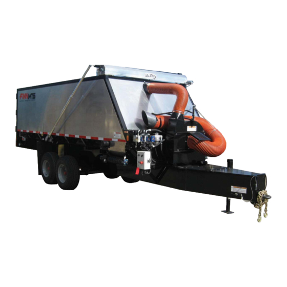
- Page 1 Activate Activate Your Warranty Your Warranty By Registering By Registering TODAY!!! TODAY!!! 9281 LeSaint Drive • Fairfield, Ohio 45014 Phone (513) 874-2818 • Fax (513) 874-2914 Sales: 800-543-7166 MATERIAL TRANSFER SYSTEM Parts and Operator’s Manual Model SR Serial No. _____________...
- Page 2 NOTES...
- Page 3 ▪ Completely fill out the Parts Tag. ▪ Attach the Parts Tag to the defective part(s). ▪ Return the part(s) and the completed Warranty Claim Form to FINN Corporation using the return shipping label. (Within 2 weeks) ▪ Tape the Orange identifier sheet, marked with the W/RMA#, on the outside of the box in which you are shipping the defective part(s).
- Page 4 Follow the instruction sheet, on property damage sustained by a person claiming to be a third party how to use your Finn Oil Analysis Kit that comes with the Kit. Failure beneficiary of a surviving warranty under the law of any jurisdiction.
-
Page 5: Table Of Contents
The FINN MTS & How It Works........ - Page 6 TARP REAR TOOL HYDRAULICS VALVE QUICK DUMP CONTROL BOX CURB SIDE MAIN SIDE CONVEYOR CONTROL BOX DEBRIS VAC FUEL RESERVOIR FRONT TOOL BOX STREET SIDE CONTROL BOX STREET SIDE HYDRAULIC SIDE CONVEYOR OIL RESERVOIR AND FILTER ENGINE AND BATTERY MATERIAL TRANSFER SYSTEM...
-
Page 7: Safety First
SAFETY FIRST With any piece of equipment, new or used, the most important part of its operation is SAFETY! FINN Corporation encourages you and your employees to familiarize yourselves with your new equipment and stresses safe operation. The first five pages of this manual are a summary of the main safety aspects associated with this unit. -
Page 8: Mts Safety Summary Section
MTS SAFETY SUMMARY SECTION It is important that all operators of this machine are familiar with all of the safety aspects covered in this section and have read the entire Operator’s Manual before operating the machine. Always keep a copy of this manual with the machine. - Page 9 To prevent accidental MTS Delivery/Unloading starting, disconnect battery When a crane is used to unload a FINN MTS unit a cables. Tag the engine oper- spreader bar is required to avoid damage. Please see ating area to show that the the photo below for example.
-
Page 10: Current Set Of Safety Decals
CURRENT SET OF SAFETY DECALS... - Page 11 NOTES...
-
Page 12: Operation & Maintenance For Mts
MATERIAL TRANSFER SYSTEM INTRODUCTION: The FINN corporation would like to thank you for your latest FINN purchase. In our efforts to main- tain a quality and growing relationship with each customer, we would like to encourage you to contact us for help with service, genuine replacement parts, or any other information you may require. This manual gives you step-by-step instructions for the operation and maintenance of the FINN MTS. -
Page 13: Pre-Start Equipment Check
PRE-START EQUIPMENT CHECK: WARNING Equipment check is made with the engine off and all rotating parts stopped. Failure to comply could result in death or serious injury. Safety check to ensure operator safety: 1. Ensure that bolts on the hitch, safety chains, lights, brakes, and breakaway switch are all in proper working order. -
Page 14: Controls
CONTROLS: Your MTS is equipped with three separate control stations. The main control box is located on the curb side of the unit and allows the operator to control all functions regarding the movement of either belt floor (See Figure 3). Also at the main control box is the ignition switch for the engine (1), with throttle cable and choke control (2), as well as control for the tarp (3). -
Page 15: Operation
On the hydraulic valve are knobs that allow the operator to adjust the speed setting on the main floor, as well as the side conveyor (See Figure 6). Turning the knob into the valve slows the function down, while turning the knob out of the valve will increase the speed of the function. SIDE CONVEYOR MAIN FLOOR CURB SIDE... -
Page 16: Tracking A Conveyor Belt
TRACKING A CONVEYOR BELT: 1. The basic rule of tracking a conveyor belt is the belt moves toward that end of the roll/idler that it contacts first. The reader can demostrate this rule very simply by laying a round pencil on a flat surface in a skewed position. -
Page 17: Maintenance
6. Add fuel stabilizer to fuel tank. HYDRAULIC SYSTEM The hydraulic system on your FINN MTS is designed to give trouble-free service, when properly main- tained. The most important areas of maintenance are the hydraulic oil and filtration. The reservoir holds 20 gal (76 L) of Mobil DTE-13M hydraulic fluid. -
Page 18: Conveyor Belt Assembly And Service
CONVEYOR BELT ASSEMBLY AND SERVICE BREAK-IN AND ADJUSTMENT OF CONVEYOR BELTS the conveyor belts in the MTS have been pre-tensioned by the factory, prior to delivery, but due to a stretch factor of up to 1-1/2%, will need to be retensioned after the initial use and possibly, after the first few uses. -
Page 19: Measurements
MEASUREMENTS At this approximate location, take a measurement between the underside of the belt and top rail, as shown below. A properly tensioned floor should be between 3-3/8 in. and 3-1/2 in. (See figure 10 below.) 102-1/16" 102-1/16" 3-3/8" - 3-1/2" FIGURE 10 Figure 3 FLOOR... -
Page 21: Lubrication Chart
LUBRICATION CHART R ef. N o. Location Lubricant F requency N o. M ain F loor T ak e-U p B earings W eek ly M ain F loor D rive B earing W eek ly M ain F loor G earbox 50,100, then S easonally 1 S ide C onveyor T ak e-U p B earings W eek ly... - Page 22 NOTES...
-
Page 23: Mts Parts Manual
MATERIAL TRANSFER SYSTEM Parts Manual Model SR... - Page 24 WHEN ORDERING PARTS, BE SURE TO STATE SERIAL NUMBER OF MACHINE MTS15-SR Rev B...
-
Page 25: Mts Parts
MTS PARTS Ref. No. Part Number Description No. Req’d 345048 Rear Door Latch 345057 Rear Door Pin 369510 Door Turn Buckle FMTS15-0034 Flapper Door FMTS15-0035 Flapper Door Spacer 345047 Flapper Door Hinge FMTS15-0004 Rear Door 002909 Handle (Not Shown) FMTS15-0028 Rear Tool Box Door 005592 Soft Latch... - Page 26 23 24 MTS PARTS CONTINUED Ref. No. Part Number Description No. Req’d 008706 Filter Breather 080329 Sight Gauge 008704 High Pressure Filter 345116 Conveyor Door Hinge FMTS15-0063 Conveyor Door LHS FMTS15-0064 Conveyor Door RHS FMTS15-0061 Conveyor Door Mount 005433 Soft Latch FMTS15-0026 Rear Tool Box Mount FMTS15-0024...
-
Page 27: Mts Safety Lights
MTS SAFETY LIGHTS Ref. No. Part Number Description No. Req’d 345014 LED Red Side Marker Light 345013 LED Tail Light 345015 LED License Light 345016 LED Amber Side Marker Light 345017 Sidemarker Light Pigtail 345018 Side Marker Light Guard 345019 LED 3 Bar Light WHEN ORDERING PARTS, BE SURE TO STATE SERIAL NUMBER OF MACHINE... - Page 28 WHEN ORDERING PARTS, BE SURE TO STATE SERIAL NUMBER OF MACHINE MTS15-SR Rev B...
-
Page 29: Hopper Main Floor Assembly
HOPPER MAIN FLOOR ASSEMBLY Ref. No. Part Number Description No. Req’d 345008 Main Floor Motor 345002 Auburn Gear Box-Main Floor FMTS15-0005 Main Floor Gear Box Mount 345137 Main Floor Drive Roll 045019 Bearing 345111 Front Engine Guard Bar 345113 Rear Engine Guard Bar 345032 MTS15 Engine Assembly FMTS15-0057... -
Page 30: Mts Side Conveyor Assembly
MTS SIDE CONVEYOR ASSEMBLY Ref. No. Part Number Description No. Req’d 345009 Side Conveyor Motor 055267-01 Motor Mount FMTS15-0015 Side Conveyor Coupling Guard 345026 Drive Coupling-1” 345028 Side Conveyor Belt Skirt FMTS15-0002 Side Conveyor Frame 340024 Bearing 345004 Side Conveyor Drive Roll 345030 Side Conveyor Belt 345005... -
Page 31: Leaf Vacuum Assembly
LEAF VACUUM ASSEMBLY Ref No Part Number Description No. Req’d FMTS15-0006 Leaf Vacuum Housing FMTS15-0023 Suction Flange FMTS15-0022 Cover Plate 345007 Leaf Vacuum Motor FMTS15-0027 Leaf Vacuum Blade Weldment 345056 Suction Flange Guard 345060 Vacuum Discharge Hose 5' Long 345062 Leaf Vacuum Handle 190029 Chain 4' Long... -
Page 32: Control Box Schematic
CONTROL BOX SCHEMATIC WHEN ORDERING PARTS, BE SURE TO STATE SERIAL NUMBER OF MACHINE MTS15-SR Rev B... - Page 33 WHEN ORDERING PARTS, BE SURE TO STATE SERIAL NUMBER OF MACHINE MTS15-SR Rev B...
-
Page 34: Mts Main Control Box
MTS MAIN CONTROL BOX Ref. No. Part Number Description No. Req’d 345169 Main Control Box Assy. 080654 Marine Starter Switch 045055 Panel Mount Cir. Brk. (Not Shown) 345051 3-Position Toggle Switch 345052 Contact Block w/Holder (Not Shown) 345053 Selector Switch 345054 2-Position Toggle Switch 345055... -
Page 35: Mts Quick Dump Control Box Assembly
MTS QUICK DUMP CONTROL BOX ASSEMBLY Ref. No Part Number Description No. Req’d 345036 Street Side Control Box 345053 Momentary Selector Switch 345052 Contact Block w/Holder (Not Shown) 345055 E-Stop Switch MTS STREET SIDE CONTROL BOX ASSEMBLY Ref. No Part Number Description No. -
Page 36: Trailer Brake Wiring Harness
TRAILER BRAKE WIRING HARNESS Ref. No. Part Number Description No. Req’d 190005 2 Conductor Cable-Gray 190005 2 Conductor Cable-Gray 190005 2 Conductor Cable-Gray 190005 2 Conductor Cable-Gray 190011 3/8" Loom 190011 3/8" Loom 190011 3/8" Loom 170012 16-14 Butt Connector 170014 12-10 Butt Connector WHEN ORDERING PARTS, BE SURE TO STATE... -
Page 37: Trailer Wiring Harness
Rear Tail Lights TRAILER WIRING HARNESS Ref. No. Part Number Description No. Req’d 190010 1/2” Loom 190011 3/8" Loom 190004 6 Conductor Cable 190051 Black Wire 16 Ga 190056 Brown Wire 190055 Green Wire 16 Ga 190052 Red Wire 16 Ga 190057 White Wire 16 Ga 190053... -
Page 38: Hydraulic Sysytem
WHEN ORDERING PARTS, BE SURE TO STATE SERIAL NUMBER OF MACHINE MTS15-SR Rev B... - Page 39 HYDRAULIC SYSTEM Ref. No. Part Number Description No. Req’d 345083 Suction Hose 345084 Suction Hose 345085 Return Hose 345086 3/4" Hose 345087 3/4" Hose 345088 3/4" Hose 345089 3/4" Hose 345090 1/2" Hose 345091 1/2" Hose 345092 3/8" Hose 345093 3/8"...
-
Page 40: Mts Tow And Tarp Assembly
MTS TOW AND TARP ASSEMBLY Ref. No. Part Number Description No. Req’d 075592 7-Blade RV Style Trailer Plug 023424 Breakaway Switch 041007 Tow Ring 190033 Chain 005796 Grab Hook 004888 Coupling Links (Not Shown) 080701 Drop Leg Jack 345012 Tarp Kit Assy RR31050 3/4"... -
Page 41: Mts Tarp Wiring For Motor
MTS TARP WIRING FOR MOTOR WHEN ORDERING PARTS, BE SURE TO STATE SERIAL NUMBER OF MACHINE MTS15-SR Rev B... - Page 42 MATERIAL TRANSFER SYSTEM AWAY E-STOP TOWARDS SIDE CONVEYOR LEAF MAIN FLOOR CONVEYOR E-STOP MATERIAL TRANSFER SYSTEM WHEN ORDERING PARTS, BE SURE TO STATE SERIAL NUMBER OF MACHINE MTS15-SR Rev B...
-
Page 43: Decals
DECALS Ref. No. Part Number Description No. Req’d 345038 MTS15 Decal Sheet 023174 "FINN" Decal Large 345068 "MTS" Decal Large 007231 "Service Weekly" Decal 012278 "WARNING Burn Hazard" Decal 031463B "WARNING Severe Hazard" Decal 345077 Street Side Control Box Decal 012687 "CAUTION Hydraulic Fluid Only"... -
Page 44: Mts Spare Parts List
MTS SPARE PARTS LIST Part Number Description No. Req’d 011784 Hydraulic Oil Filter 008703 Low Pressure Filter Replacement Cartridge 008705 High Pressure Filter Replacement Cartridge 080566 Throttle Control Cable Assembly 080567 Choke Cable Assembly KL1205001 Oil Filter KL2488303-S1 Air Filter KL2406857-S Muffler KL2405013-S... -
Page 45: Leaf Vacuum Retrofit Kit
Replaces Original Discharge Hose Configuration ORIGINAL LEAF VACUUM ASSEMBLY LEAF VACUUM RETROFIT KIT LEAF VACUUM RETROFIT KIT Ref No Part Number Description No. Req’d 345122 Leaf Vacuum Retrofit Kit 345123 8 in. Bridge Clamp 345120 Extension Tube 345119 8 in. Hose Clamp 345118 8 in.
Need help?
Do you have a question about the MTS SR and is the answer not in the manual?
Questions and answers