Sign In
Upload
Download
Table of Contents
Contents
Add to my manuals
Delete from my manuals
Share
URL of this page:
HTML Link:
Bookmark this page
Add
Manual will be automatically added to "My Manuals"
Print this page
×
Bookmark added
×
Added to my manuals
Manuals
Brands
Finn Manuals
Industrial Equipment
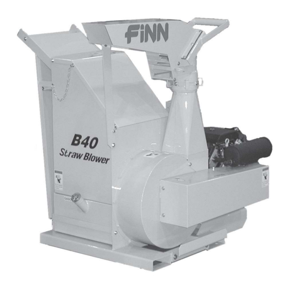
B-40
Parts and operator's manual
Finn B-40 Parts And Operator's Manual
Straw blower
Hide thumbs
Also See for B-40
:
Parts and operator's manual
(28 pages)
1
2
3
4
Table Of Contents
5
6
7
8
9
10
11
12
13
14
15
16
17
18
19
20
21
22
23
24
25
26
27
28
29
30
31
32
33
34
35
page
of
35
Go
/
35
Contents
Table of Contents
Bookmarks
Table of Contents
Table of Contents
Safety First
Straw Blower Safety Summary Section
Introduction
Definition of Mulching
The FINN B-40 Straw Blower and How It Works
Towing Vehicle
Loading Bales
Pre-Start Check
Equipment Check
Starting Procedure
Crew Members and Their Duties
Blower Discharge
Cleaning and Maintenance
After First 4 to 8 Hours of Operation
Daily Clean-Up and Maintenance
Every 50 Hour Maintenance
Every 100 Hour Maintenance
Lubrication and Fluids Chart
Straw Blower Parts Manual Section
Tool Kit
Blower Shaft Assembly
Discharge Head Assembly
Beater Box and Feed Chute
Control Box Wiring
Trailer Wiring
Trailer Assembly
Axle and Hub Assembly
Decals
Trailer Safety Decals
Advertisement
Quick Links
1
Straw Blower Parts Manual Section
2
Discharge Head Assembly
3
Control Box Wiring
Download this manual
B40 MUA2018 Rev A
9281 LeSaint Drive • Fairfield, Ohio 45014
Phone (513) 874-2818 • Fax (513) 874-2914
Sales: 1-800-543-7166
B-40 Straw Blower
Parts and Operator's Manual
Model MUA
Serial No. _____________
Activate
Activate
Your Warranty
Your Warranty
By Registering
By Registering
TODAY!!!
TODAY!!!
Table of
Contents
Previous
Page
Next
Page
1
2
3
4
5
Advertisement
Table of Contents
Need help?
Do you have a question about the B-40 and is the answer not in the manual?
Ask a question
Questions and answers
Related Manuals for Finn B-40
Spreader Finn B-40 Parts And Operator's Manual
Mulch spreader (28 pages)
Industrial Equipment Finn B70 Operator Instructions And Parts Manual
Straw blower (89 pages)
Industrial Equipment Finn HydroSeeder Series Practical Service Manual For The Parts Professional
(51 pages)
Industrial Equipment Finn MTS SR Parts And Operator's Manual
(45 pages)
Industrial Equipment Finn 5 Series Operator Instructions And Parts Manual
(85 pages)
Industrial Equipment Finn T30 HydroSeeder MO Parts And Operator's Manual
(55 pages)
Industrial Equipment Finn HydroSeeder T30 Parts And Operator's Manual
(61 pages)
Industrial Equipment Finn HydroSeeder T90-II Operator's Manual
(83 pages)
Industrial Equipment Finn MBH6 Mounting Instructions Manual
(12 pages)
This manual is also suitable for:
Mua
Table of Contents
Save PDF
Print
Rename the bookmark
Delete bookmark?
Delete from my manuals?
Login
Sign In
OR
Sign in with Facebook
Sign in with Google
Upload manual
Upload from disk
Upload from URL


Need help?
Do you have a question about the B-40 and is the answer not in the manual?
Questions and answers