Table of Contents
Advertisement
Quick Links
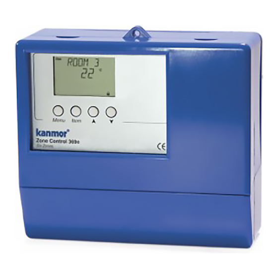
Zone Control 369e
The Zone Control 369e is designed to control the temperature in up to six heating zones using Room Temperature Units (RTUs)
or indoor sensors. The 369e allows one stage heating zones, two stage heating zones, or a combination of one stage and two
stage heating zones. PID zoning logic allows for a staggering and synchronization of multiple zones in order to minimize boiler
short cycling. The 369e is capable of operating a single cooling output and can provide automatic or manual heat / cool change
over. When the 369e is used with a kanmor Integrated System Control, the 369e provides indoor temperature feedback that
automatically adjusts the supply water temperature in order to satisfy the zone with the highest heat load. A large Liquid Crystal
Display (LCD) is incorporated in order to view system status and operating information. The LCD and user key pad are used to set
the control's adjustments and to monitor zone running times, outdoor high and low temperatures, minimum zone temperatures,
and many other useful items.
Additional features include:
• Control Schedule
• Individual Zone Schedules
• Optimum Start / Stop
• Cooling Control or Cooling Enable
• Manual Override
Zone Control 369e
Six Zones
Input
Timer
Optional
Input
Zone
Control
Output
Integrated
System
Control
Input
Outdoor
Sensor
Included
OR
OR
M
M
Zone Pumps or Zone Valves
- Data Brochure
View
°C
Item
Menu
Do not apply power
1
2
3
4
5
6 7
8 9
10
11 12
UnO Zo
Zo Com
Out
Zn
Com
Zn
Zn
Com
Zn
Sw
In
Out
1
1-2
2
3
3-4
4
OR
OR
OR
OR
M
M
M
M
Output
• Slab Minimum and Slab Maximum Temperature Control
• Remote Display and Adjustment Capabilities
• Test Sequence to Ensure Proper Component Operation
• 230 V (ac) Power Supply
• CE Approved
13 14
15 16
17 18
19
20 21 22 23 24 25 26
Zn
Com Zn
Cooling
Sys
Power
Com tN1 tN1
5
5-6
6
Pmp
L
N
1
Input
Output
230 V (ac)
Output
System
Power
Cooling
Pump
Supply
1 of 32
Setback
off
not testing
red
testing
testing paused
red
None
Lithium Battery CR1620
POS (+) up
Press here
on battery to
remove it.
WARNING: battery may explode
or cause burns if disassembled,
recharged or exposed to fire or
high temperatures.
INSTALLATION CATEGORY II
Made in Canada
230 V ±10% 50/60 Hz 1200 VA
Power
Relays
230 V (ac) 5 A 1/4 hp, pilot duty 240 VA
Signal wiring must be rated at least 300 V.
Do not apply power
27
28
29
30
31
Indr Com tN1 tN1
Indr
Com
tN1/2
tN1
Indr
2
2
3
4
4
5
6
6
Input
Input
Room
Room
Temperature
Temperature
Unit (RTU)
Unit (RTU)
© 2003
D 369e
06/03
Input
Indoor
Sensor
Input
Room
Temperature
Unit (RTU)
Input
Remote
Display
Module
or
Input
Room
Temperature
Unit (RTU)
Input
Indoor
Sensor
Input
Room
Temperature
Unit (RTU)
Input
Room
Temperature
Unit (RTU)
Input
Indoor
Sensor
D 369e - 06/03
Advertisement
Table of Contents

Subscribe to Our Youtube Channel
Related Manuals for Kanmor Zone Control 369e


Summary of Contents for Kanmor Zone Control 369e
- Page 1 06/03 The Zone Control 369e is designed to control the temperature in up to six heating zones using Room Temperature Units (RTUs) or indoor sensors. The 369e allows one stage heating zones, two stage heating zones, or a combination of one stage and two stage heating zones.
-
Page 2: Table Of Contents
How To Use The Data Brochure This brochure is organized into four main sections. They are: 1) Sequence of Operation, 2) Installation, 3) Control Settings, and 4) Troubleshooting. The Sequence of Operation has four subsections. We recommend reading each subsection of the Sequence of Operation, as each one contains important information on the overall operation of the control. - Page 3 MENU FIELD The 369e has a number of menus used to monitor system status and adjust settings in the control. The current menu will be displayed in the left hand side of the display. View View Menu °C The View menu is used to view the outdoor temperature and zone temperatures. Adjust Menu There are seven separate menus used to make adjustments to the control settings and the zone settings.
-
Page 4: Description Of Display Elements
Display Item Field Number Field Displays an abbreviated name Displays the current value of of the selected item the selected item View Adjust Monitor Menu Field °C °F Time Displays the min hr Schd current menu Misc UnOcc Cool Zone Status Field Displays the current status of the control's... -
Page 5: Sequence Of Operation
POWERING UP THE CONTROL When the Zone Control 369e is powered up, the control displays the control type number in the LCD for 2 seconds. Next, the software version is displayed for 2 seconds. Finally, the control enters into the normal operating mode and the LCD defaults to displaying the current outdoor temperature. - Page 6 ZONE OUTPUT (ZN OUTP) The ZN OUTP adjustment in the Zone Adjust menu of the control selects the zoning device used for each zone, and affects the operation of the system pump. When PUMP is selected, the control assumes the device used to control the heat deliv- Adjust ery is a pump.
-
Page 7: Section B: Cooling
Control Section B1: General Cooling GENERAL COOLING The Zone Control 369e is capable of operating a single cooling group to provide either Adjust cooling enable (ENBL) or cooling control (CTRL). This is an adjustable item through the COOL MOD setting in the Control Adjust menu of the control. In order to prevent short cycling of the mechanical cooling unit, the 369e ensures the Cooling relay is operated for a minimum amount of time. - Page 8 HEAT / COOL CHANGEOVER The changeover between heating and cooling is based on whether or not a display RTU is connected to zone 6 (tN1 6). If a display RTU is connected to zone 6 (tN1 6), the changeover between heating and cooling is selected at RTU 6. A pointer in the lower right hand display of the RTU indicates that this RTU is the designated heat / cool RTU.
-
Page 9: Section C: Setback (Unoccupied)
Section C: UnOccupied SETBACK (UNOCCUPIED) To provide greater energy savings, the 369e can lower the building temperature at night or when the building is unoccupied. The 369e has a built-in clock which allows for heating and cooling setback capabilities. As an option, an external timer may be connected to provide a separate setback signal. -
Page 10: Section D: Tn 1 / 2 Devices
SCHEDULE OVERRIDES The 369e has a number of setback overrides that are selected through the schedule (Schd) menu. A system override and a zone override are available. Any time an override is in effect, the Ovr segment is displayed in the appropriate LCD. System Override (OVERRIDE) The system overrides affect every zone and are selected in the schedule (Schd) menu of the control, remote display module (RDM), or display RTU. - Page 11 ROOM TEMPERATURE UNIT (RTU) 063e This RTU consists of one internal air sensor, three remote temperature sensor inputs, a liquid crystal display (LCD) and four buttons. These buttons and the LCD are used to set and view the desired room temperature, and for setback overrides. The RTU’s LCD displays the current room temperature, the outdoor air temperature, temperature at the slab sensor, and a number of other items.
-
Page 12: Installation
Check the contents of this package. If any of the contents listed are missing or damaged, please contact your wholesaler or kanmor sales representative for assistance. Type 369e includes: One Zone Control 369e, One Outdoor Sensor 070e, Data Brochures D 369e, D 070e, User Brochure U 369e. -
Page 13: Electrical Connections
STEP THREE ROUGH-IN WIRING All electrical wiring terminates in the control base wiring chamber. The base has standard 22 mm knockouts which accept common wiring hardware and conduit fittings. Before removing the knockouts, check the wiring diagram and select those sec- tions of the chamber with common voltages. - Page 14 Zo Out terminal on the second 369e to the Zo In terminal on the third 369e and continue this process for each additional 369e. The Zo Out terminal on the last 369e in the chain can be connected to the Zo In terminal on a kanmor Integrated System Control. From additional Note: The wires from the zone control are polarity sensitive.
-
Page 15: Testing The Wiring
Zone 3 (tN1 3) Connect the Com terminal from the RTU to the Com terminal (24) on the 369e. Connect the tN1 terminal from the RTU to the tN1 3 terminal (25) on the 369e. Zone 4 (tN1 4 or Indr 4) Connect the Com terminal from the RTU to the Com terminal (24) on the 369e. - Page 16 Test The Power Supply 207 to 253 V (ac) Make sure exposed wires and bare terminals are not in contact with other wires or grounded surfaces. Turn on the power and measure the voltage between the Power L and Power N termi- nals (18 and 19) using an AC voltmeter.
-
Page 17: Dip Switch Settings
Access Levels The kanmor Zone Control 369e comes with four Access Level settings. These Access Levels restrict the number of Menus, Items, and Adjustments that can be accessed by the user. The four access levels are Limited (LTD), User (USER), Installer (INST) and Advanced (ADV). -
Page 18: Control Settings
View Menu (1 of 1) Access Level Item Field Description Range – – –, -67 to 149°F Current outdoor temperature as measured by the outdoor (– – –, -55 to 65°C) sensor. – – –, -58 to 167°F Current room air temperature of zone 1. (–... - Page 19 Control Adjust Menu (2 of 2) Access Level Actual Item Field Description Range Setting The time the heating zones assigned to the cooling group must be off before cooling 0:10 to 3:00 hr operation is allowed. Default = 0:30 hr COOL MOD ≠...
-
Page 20: Monitor Menu
Zone Adjust Menu (2 of 2) Access Level Actual Item Field Description Range Setting 35 to 100°F Desired room air temperature during an (2 to 38°C) occupied perid. Default = 70°F (21°C) (Indoor sensor is present) 35 to 100°F Desired room air temperature during an (2 to 38°C) unoccupied perid. -
Page 21: Time Menu
Monitor Menu (2 of 2) Note: To clear the recorded information in the specifi c item fi eld, press and hold ▲ and ▼ . Access Level Item Field Description Range The total number of Zn 6 relay running hours since this item 0 to 9999 hr was last cleared. -
Page 22: Schedule Menu
Schd (Schedule) Menu (1 of 1) Access Level Item Field Description Range NONE, TMPY Occ Ovr, The type of setback override that is in effect for all PERM Occ Ovr, TMPY schedules. UnOcc Ovr, PERM DIP switch = Setback UnOcc Ovr, HOL HOL is available even if DIP switch ≠... -
Page 23: Miscellaneous Menu
Room Temperature Units (RTUs) 062e and 063e A display RTU may be connected to the Zone Control 369e in order to provide the control with indoor temperature feedback for the heating system. When using display RTUs, several items related to the system are no longer available in the control’s User Interface. - Page 24 RTU Adjust Menu (1 of 1) Access Level Item Field Description Range The operating mode for this zone. OFF, HEAT RTU 1 to 5 or RTU 6 if COOL MOD = NONE Default = HEAT OFF, HEAT, AUTO, The operating mode for this zone. COOL RTU 6 only and COOL MOD ≠...
- Page 25 RTU Monitor Menu (1 of 1) Note: To clear the recorded information in the specifi c item fi eld, press and hold ▲ and ▼ . Access Level Item Field Description Range -67 to 140°F The highest outdoor air temperature recorded since (-55 to 60°C) this item was last cleared.
- Page 26 RTU Schd (Schedule) Menu (1 of 1) Access Level Item Field Description Range NONE, TMPY Occ Ovr, The type of setback override that is in effect for all PERM Occ Ovr, TMPY schedules. UnOcc Ovr, PERM DIP switch = Setback UnOcc Ovr, HOL Ovr HOL is available even if DIP switch ≠...
-
Page 27: Testing And Troubleshooting
RTU1 . . . RTU6 connected to. Testing the Control The Zone Control 369e has a built-in test routine which is used to test the main control not testing functions. The 369e continually monitors the sensors, and displays an error message testing whenever a fault is found. - Page 28 MAX HEAT (MAX HEAT) The Zone Control 369e has a function called Max Heat. In this mode, the control sets all RTU room temperature settings to 75°F (24°C) and turns on the required contacts. The RTU room setting may be adjusted to turn on or off the required zone without delay.
-
Page 29: Error Messages
Document the control for future reference. Before making any adjustments to the control, note down Document the all of the items that the control is currently displaying. This includes items such as error messages, Control current temperatures and settings, and which devices should be operating as indicated by the LCD. This information is an essential step if additional assistance is required to diagnose the problem. - Page 30 Error Messages (2 of 3) The error messages listed below for RTU 1 will be the same for RTU 2, RTU 3, RTU 4, RTU 5 and RTU 6. RTU 1 was unable to store a piece of information into its EEPROM. This error can be caused by a noisy power source.
- Page 31 Error Messages (3 of 3) The error messages listed below for RTU 1 will be the same for RTU 2, RTU 3, RTU 4, RTU 5 and RTU 6. Error Displayed Description of Error The control is no longer able to read the information that is coming from RTU 1. Reconnect RTU 1 and press either the Menu or Item button to clear the error.
-
Page 32: Technical Data
Any representations or warranties about the Products made by Purchaser obligation shall be to provide the address and other contact information to its customers which are different from or in excess of the kanmor Limited regarding the appropriate Representative. kanmor Control Systems Ltd.
Need help?
Do you have a question about the Zone Control 369e and is the answer not in the manual?
Questions and answers