Advertisement
Table of Contents
- 1 Table of Contents
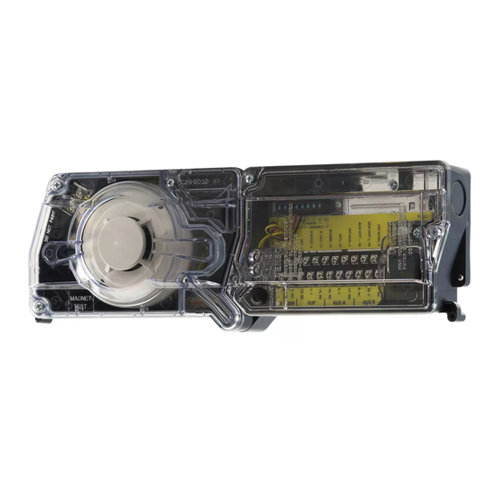
- 2 Exploded View of Duct Smoke Detector Components
- 3 General Description
- 4 Limitations of Duct Smoke Detectors
- 5 Contents of Duct Smoke Detector Kit
- 6 Detector Installation
- 7 Sampling Tube Installation
- 8 Field Wiring
- 9 Duct Smoke Detector Testing & Maintenance
- 10 Detector Cleaning
- 11 Sensor Placement
- 12 Wiring Diagrams
- Download this manual
INSTALLATION AND MAINTENANCE INSTRUCTIONS
D4120 Air Duct Smoke Detector with Extended
Air Speed Range, D4S Air Duct Smoke Detector
Sensor Component, D4P120 Air Duct Smoke
Detector Power Board Component
NOTE: D4S Sensor Component and D4P120 Power Board Component to be used in conjunction with the model D4120 air duct smoke detector only.
Specifications
Operating Temperature:
Storage Temperature:
Humidity:
Air Velocity:
D4120 Footprint Dimensions:
D4S/D4P120 Footprint Dimensions: 7.75"L x 5"W x 2.5"D (19.7cm L x 12.7cm W x 6.35cm D)
D4120 Weight:
Electrical
Power supply voltage:
Input capacitance:
Reset Voltage:
Reset Time (with RTS451):
Reset Time (by power down):
Power Up Time:
Alarm response time:
Sensitivity Test:
Current Requirements (Using No Accessories)
Max. standby current
Max. alarm current
CONTACT RATINGS
Alarm initiation contacts (SPST)
Alarm auxiliary contatcs (DPDT)
NOTE: Alarm auxiliary contacts shall not be connected to initiating circuits of control
panels. Use the alarm initiation contact for this purpose.
Trouble Contacts (SPDT)
TABLE 1. Detector Status Indications
Sensor LED
Status
Designation
Sensor
Red Blink every 5
Initialization
seconds
Green Blink every
Standby
5 seconds
Green Blink every
Trouble
5 seconds
Red Blink every 5
Maintenance
seconds
Alarm
Solid Red
NOTE: Each power board has a unique LED to designate each of 2 possible sensors. If only one sensor is connected, the Sensor 2 LED will not illuminate.
Table of Contents
[1] Exploded View of Duct Smoke Detector Components . . . . . . . . . . . . . 2
[2] General Description . . . . . . . . . . . . . . . . . . . . . . . . . . . . . . . . . . . 2
[3] Limitations of Duct Smoke Detectors . . . . . . . . . . . . . . . . . . . . . . . 2
[4] Contents of Duct Smoke Detector Kit . . . . . . . . . . . . . . . . . . . . . . . 2
[5] Detector Installation . . . . . . . . . . . . . . . . . . . . . . . . . . . . . . . . . . . 2
[6] Sampling Tube Installation . . . . . . . . . . . . . . . . . . . . . . . . . . . . . . . 3
SS-300-000
-4° to 158° F (-20° to 70° C)
-22° to 158° F (-30° to 70° C)
0% to 95% R.H. non-condensing
100 to 4000 ft./min. (0.5 to 20.3 m/sec.)
Rectangular - 14.38˝ L x 5˝ W x 2.5˝ D (37cm L x 12.7cm W x 6.36cm D)
Square - 7.75" L x 9" W x 2.5" D (19.7cm L x 22.9cm W x 6.35cm D)
2.5 pounds; 1.14 kg
20-29 VDC
270 µF max.
3.0 VDC min.
.03 to 0.3 sec.
0.6 sec. max.
35 sec. max.
15 sec.
See detector label
25 mA @ 24 VDC
60 mA @ 24 VDC
2.0A @ 30 VDC (resistive)
10A @30 VDC (resistive)
10A @250 VAC (resistive)
/
HP @240 VAC
1
2
/
HP @120 VAC
1
4
2.0A @ 30 VDC (resistive)
2.0A @ 125 VAC (resistive)
Power Board
LED
Designation
Alternating
At power up or reset at the panel the sensor will take approximately 30 seconds to initialize. Also occurs
Green/Amber
when sensor is removed during a seven minute delay.
The LED on the sensor and the power board should flash approximately every 5 seconds. If the detector
Green Blink every
and power board LEDs are not illuminated, then the detector lacks power (check wiring, panel or power
5 seconds
supply).
The cover has been missing or is not secured properly for more than 7 minutes, if the cover tamper feature
is "ON" (factory default). See Figure 13. OR Sensor +, - wires are shorted. Check connections.
Amber Solid
NOTE: If the power board Solid Amber flashes once every ten seconds the unit is not receiving valid data
from sensor. Ensure the sensor is secured in place and the sensor +, - wires are properly connected.
Amber Blink
The sensor is outside of its sensitivity limits and shall be cleaned or replaced. See section 9 for details.
Solid Red
The unit is in alarm.
24 VAC 50-60-Hz
270 µF max.
2.0 VAC min.
.03 to 0.3 sec.
0.6 sec. max.
35 sec. max.
15 sec.
See detector label
55 mA RMS @ 24VAC 60Hz
130 mA RMS @ 24 VAC 60 Hz
ACCESSORY CURRENT LOADS AT 24 VDC
DEVICE
APA151/APA451
MHR/MHW
RA400Z
RTS451
RTS451KEY
SSK451
*NOTE: When a unit is powered at the 120VAC input, any combination
of accessories may be used such that the given accessory loads are:
60mA or less in the standby state, 110mA or less in the alarm state.
Description/Trouble Shooting
Page
Table of Contents
[7] Field Wiring . . . . . . . . . . . . . . . . . . . . . . . . . . . . . . . . . . . . . . . . . 4
[8] Duct Smoke Detector Testing & Maintenance . . . . . . . . . . . . . . . . . 4
[9] Detector Cleaning . . . . . . . . . . . . . . . . . . . . . . . . . . . . . . . . . . . . . 5
[10] Sensor Placement . . . . . . . . . . . . . . . . . . . . . . . . . . . . . . . . . . . . 5
Wiring Diagrams . . . . . . . . . . . . . . . . . . . . . . . . . . . . . . . . . . . . . . .6-8
Warranty
. . . . . . . . . . . . . . . . . . . . . . . . . . . . . . . . . . . . . . . . . . . 8
1
3825 Ohio Avenue, St. Charles, Illinois 60174
1-800-SENSOR2, FAX: 630-377-6495
www.systemsensor.com
120 VAC 50-60 Hz
N/A
10 VAC min.
.03 to 0.3 sec.
0.6 sec. max.
35 sec. max.
15 sec.
See detector label
20 mA RMS* @ 120 VAC 60 Hz
35 mA RMS* @ 120 VAC 60 Hz
STANDBY
TROUBLE
12.5mA
n/a
0mA
n/a
0mA
n/a
0mA
n/a
12mA*
n/a
5mA Max.
9mA Max.
ALARM
30mA Max.
29mA Max.
10mA Max.
7.5mA Max.
7.5mA Max.
30mA Max.
Page
I56-2967-000R
Advertisement
Table of Contents

Subscribe to Our Youtube Channel
Related Manuals for System Sensor D4120


Summary of Contents for System Sensor D4120
-
Page 1: Table Of Contents
1-800-SENSOR2, FAX: 630-377-6495 Detector Power Board Component www.systemsensor.com NOTE: D4S Sensor Component and D4P120 Power Board Component to be used in conjunction with the model D4120 air duct smoke detector only. Specifications Operating Temperature: –4° to 158° F (–20° to 70° C) Storage Temperature: –22°... -
Page 2: Exploded View Of Duct Smoke Detector Components
H0549-00 MAGNET TEST LOCATION Before Installing user read NFPA Standards 90A, 72, and 101. The D4120 Air Duct Smoke Read the System Sensor Guide for Proper Use of Smoke Detectors in Duct Detectors are listed per UL 268A. Applications (A05-1004), which provides information on detector spac- This device will not operate without electrical power. -
Page 3: Sampling Tube Installation
Figure 2: The sampling tube is always installed with the air inlet holes facing into the air flow. To assist proper installation, the tube’s connector is marked with an arrow. Make sure the sampling tube is mounted so that the arrow points into the airflow as shown in Figure 3. -
Page 4: Field Wiring
[7.1] Wiring Instructions auxiliary functions (i.e fan shutdown, damper control, etc.). The D4120 and D4P120 detectors are designed for easy wiring. The hous- 3. The detector must be reset by the system control panel, front cover ing provides a terminal strip with clamping plates. The D4S housing pro- Test/Reset button, or remote accessory. -
Page 5: Detector Cleaning
5 seconds. Note in a maintenance condition the sensor LEDs will blink red every 5 seconds and power board will blink amber as depicted in Table 1. The D4120 is designed to operate over an extended air speed range of 100 to The maintenance condition indicates that the sensor is operating outside 4000 FPM. -
Page 6: Wiring Diagrams
Up to 10 DH100ACDC units may be interconnected. When interconnecting D4120 units with DH100ACDC units, three D4120’s may be substi- tuted for every one DH100ACDC. For example, nine DH100ACDC units may be interconnected with up to three D4120 units. A maximum of 27 D4120 units may be interconnected with one DH100ACDC. - Page 7 – ACC – ACC – SUP. SIGNAL (GREEN LED) POWER NOTE: WIRING DIAGRAM SHOWN IS FOR D4120 4-WIRE DUCT SMOKE DETECTOR FOR RTS451KEY ONLY WITHOUT A CONTROL PANEL SYSTEM EQUIPPED WITHOUT A CONTROL PANEL. H0582-00 H0583-00 NOTE: Wiring diagram shown is for D4120 4-wire duct smoke detector system equipped without a control panel.
- Page 8 Please refer to insert for the Limitations of Fire Alarm Systems Three-Year Limited Warranty System Sensor warrants its enclosed product to be free from defects in materials and workman- Department, RA #__________, 3825 Ohio Avenue, St. Charles, IL 60174. Please include a note ship under normal use and service for a period of three years from date of manufacture.
Need help?
Do you have a question about the D4120 and is the answer not in the manual?
Questions and answers