Sign In
Upload
Manuals
Brands
4RF Manuals
Radio
Aprisa SR+
4RF Aprisa SR+ Manuals
Manuals and User Guides for 4RF Aprisa SR+. We have
6
4RF Aprisa SR+ manuals available for free PDF download: User Manual, Product Description, Manual, Quick Start Manual
4RF Aprisa SR+ User Manual (492 pages)
Brand:
4RF
| Category:
Radio
| Size: 16 MB
Table of Contents
Table of Contents
11
1 Getting Started
17
2 Introduction
19
About this Manual
19
What It Covers
19
Who Should Read It
19
Contact Us
19
What's in the Box
20
3 About the Radio
21
The 4RF Aprisa SR+ Radio
21
Product Features
22
Functions
22
Security
24
Performance
25
Usability
25
Product Overview
26
Network Coverage and Capacity
26
Automatic Registration
26
Remote Messaging
26
Store and Forward Repeater
27
Repeater Packet Forwarding
27
Repeater Messaging
30
Peer to Peer Communication between Remote Radios
31
Architecture
33
Product Operation
33
Physical Layer
33
Data Link Layer / MAC Layer
34
Channel Access
34
Hop by Hop Transmission
35
Adaptive Coding and Modulation
35
System Gain Vs FEC Coding
36
Network Layer
37
Packet Routing
37
Static IP Router
38
Bridge Mode with VLAN Aware
53
VLAN Bridge Mode Description
54
Terminal Server Operational in Bridge and Router Modes
56
Avoiding Narrow Band Radio Traffic Overloading
60
Interfaces
62
Antenna Interface
62
Ethernet Interface
62
RS-232 / RS-485 Interface
62
USB Interfaces
62
Protect Interface
62
Alarms Interface
62
Front Panel Connections
63
LED Display Panel
64
Normal Operation
64
Single Radio Software Upgrade
65
Network Software Upgrade
65
Test Mode
66
Network Management
67
Hardware Alarm Inputs / Outputs
68
Alarm Input to SNMP Trap
68
Alarm Input to Alarm Output
68
Aprisa SR Alarm Input to Aprisa SR+ Alarm Output
68
4 Implementing the Network
69
Network Topologies
69
Point-To-Point Network
69
Point-To-Multipoint Network
69
Point-To-Multipoint with Repeater 1
69
Point-To-Multipoint with Repeater 2
69
Initial Network Deployment
70
Install the Base Station
70
Installing the Remote Radios
70
Install a Repeater Station
70
Network Changes
71
Adding a Repeater Station
71
Adding a Remote Radio
71
5 Preparation
73
Bench Setup
73
Path Planning
74
Antenna Selection and Siting
74
Base or Repeater Station
74
Remote Radio
75
Antenna Siting
76
Coaxial Feeder Cables
77
Linking System Plan
77
Site Requirements
78
Power Supply
78
Equipment Cooling
78
Earthing and Lightning Protection
79
Feeder Earthing
79
Radio Earthing
79
6 Installing the Radio
80
Mounting
80
Required Tools
80
DIN Rail Mounting
81
Rack Shelf Mounting
82
Wall Mounting
83
Installing the Antenna and Feeder Cable
84
Connecting the Power Supply
85
External Power Supplies
85
7 Managing the Radio
87
Supervisor
87
Connecting to Supervisor
88
Management PC Connection
89
PC Settings for Supervisor
90
Login to Supervisor
94
Logout of Supervisor
97
Supervisor Page Layout
98
Supervisor Extended Network Management (EXM)
100
Supervisor Menu
102
Supervisor Menu Access
103
Supervisor Menu Items
105
Standard Radio
106
Terminal
106
Radio
127
Serial
149
Ethernet
168
Qos
204
Security
226
Maintenance
258
Events
278
Software
289
Monitoring
308
Network Status
331
Protected Station
340
Terminal
341
Radio
349
Ethernet
351
Security
356
Maintenance
359
Events
369
Software
373
Command Line Interface
390
Connecting to the CLI Via the Management Port (MGMT)
390
Connecting to the CLI Via Telnet
393
Connecting to the CLI Via SSH
393
CLI Commands
395
Viewing the CLI Terminal Summary
397
Changing the Radio IP Address
397
8 In-Service Commissioning
398
Before You Start
398
What You will Need
398
Antenna Alignment
399
Aligning the Antennas
399
9 Product Options
400
Radio Hardware Types
400
Data Interface Ports
401
Full Duplex Base Station
401
Point-To-Point Link
402
Protected Station
406
Protected Ports
407
Operation
407
Switch over
407
Switching Criteria
408
Monitored Alarms
409
Configuration Management
410
Hardware Manual Lock
411
Remote Control
411
L2 / L3 Protection Operation
412
Hot-Swappable
412
Antenna and Duplexer Options
413
Installation
415
Mounting
415
Cabling
416
Power
418
Alarms
418
Maintenance
419
Changing the Protected Station IP Addresses
419
Creating a Protected Station
419
Replacing a Protected Station Faulty Radio
420
Replacing a Faulty Power Supply
421
Replacing a Faulty Protection Switch
421
Spares
422
Data Driven Protected Station
423
Operation
423
Over the Air Compatibility
423
Switch over
424
Configuration Management
424
Power
424
Installation
425
Mounting
425
Cabling
425
Duplexer Kits
426
Radio Duplexer Kits
426
Protected Station Duplexer Kits
429
Protected Station with Duplexer Kit
433
USB RS-232 / RS-485 Serial Port
434
USB RS-232 / RS-485 Operation
434
USB RS-232 Cabling Options
435
USB RS-485 Cabling Options
435
USB Retention Clip
436
10 Maintenance
437
Spare Fuses
437
Radio Spare Fuses
437
Additional Spare Fuses
438
Protected Station Spare Fuses
439
No User-Serviceable Components
440
Software Upgrade
441
Network Software Upgrade
441
Non-Protected Network Upgrade Process
441
Protected Network Upgrade Process
443
Single Radio Software Upgrade
445
File Transfer Method
445
USB Boot Upgrade Method
446
Software Downgrade
446
Protected Station Software Upgrade
447
Routine Maintenance
448
Power Supply Check
448
Temperature Test
448
Connections
448
Antenna and Feeder System
448
Transmit Power
449
Transmit Frequency
449
Transmit Spectrum
449
11 Interface Connections
450
RJ45 Connector Pin Assignments
450
Ethernet Interface Connections
450
RS-232 Serial Interface Connections
451
RS-232 Pinout
451
RS-232 Customer Cable Wiring
451
RS-232 Bit Oriented Mode Wiring
452
RS-232 RJ45 LED Indicators
452
Alarm Interface Connections
453
Protection Switch Remote Control Connections
453
12 Alarm Types and Sources
454
Alarm Types
454
Alarm Events
455
Informational Events
461
13 Specifications
463
RF Specifications
463
Frequency Bands
463
Channel Sizes
464
Receiver
477
Transmitter
480
Modem
481
Data Payload Security
481
Duplexer Specifications
482
Interface Specifications
483
Ethernet Interface
483
RS-232 Asynchronous Interface
484
Hardware Alarms Interface
485
Protection Switch Specifications
485
Power Specifications
486
Power Supply
486
Power Consumption
487
Power Dissipation
488
General Specifications
489
Environmental
489
Mechanical
489
Compliance
490
14 Product End of Life
491
End-Of-Life Recycling Programme (WEEE)
491
The WEEE Symbol Explained
491
WEEE Must be Collected Separately
491
YOUR ROLE in the Recovery of WEEE
491
EEE Waste Impacts the Environment and Health
491
15 Copyrights
492
Advertisement
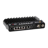
4RF Aprisa SR+ User Manual (403 pages)
Smart, secure, industry-leading speed licensed point-to-multipoint SCADA communications for industrial monitoring and control
Brand:
4RF
| Category:
Radio
| Size: 12 MB
Table of Contents
Rf Exposure Warning
8
Table of Contents
9
1 Getting Started
15
2 Introduction
17
About this Manual
17
What It Covers
17
Who Should Read It
17
Contact Us
17
What's in the Box
17
Aprisa SR+ Accessory Kit
18
Aprisa SR+ CD Contents
18
Software
18
Documentation
18
3 About the Radio
19
The 4RF Aprisa SR+ Radio
19
Product Overview
20
Network Coverage and Capacity
20
Automatic Registration
20
Remote Messaging
20
Store and Forward Repeater
21
Repeater Packet Forwarding
21
Repeater Messaging
24
Peer to Peer Communication between Remote Radios
25
Product Features
26
Functions
26
Security
27
Performance
28
Usability
28
System Gain Vs FEC Coding
29
Architecture
30
Product Operation
30
Physical Layer
30
Data Link Layer / MAC Layer
31
Channel Access
31
Hop by Hop Transmission
32
Adaptive Coding Modulation
32
Network Layer
33
Packet Routing
33
Static IP Router
34
Bridge Mode with VLAN Aware
37
VLAN Bridge Mode Description
38
Avoiding Narrow Band Radio Traffic Overloading
40
Interfaces
42
Antenna Interface
42
Ethernet Interface
42
RS-232 / RS-485 Interface
42
USB Interfaces
42
Protect Interface
42
Alarms Interface
42
Front Panel Connections
43
LED Display Panel
44
Normal Operation
44
Single Radio Software Upgrade
45
Network Software Upgrade
45
Test Mode
46
Network Management
47
Hardware Alarm Inputs / Outputs
48
Alarm Input to SNMP Trap
48
Alarm Input to Alarm Output
48
Aprisa SR Alarm Input to Aprisa SR+ Alarm Output
48
4 Implementing the Network
49
Network Topologies
49
Point-To-Point Network
49
Point-To-Multipoint Network
49
Point-To-Multipoint with Repeater 1
49
Point-To-Multipoint with Repeater 2
49
Initial Network Deployment
50
Install the Base Station
50
Installing the Remote Stations
50
Install a Repeater Station
50
Network Changes
51
Adding a Repeater Station
51
Adding a Remote Station
51
5 Preparation
53
Bench Setup
53
Path Planning
54
Antenna Selection and Siting
54
Base or Repeater Station
54
Remote Station
55
Antenna Siting
56
Coaxial Feeder Cables
57
Linking System Plan
57
Site Requirements
58
Power Supply
58
Equipment Cooling
58
Earthing and Lightning Protection
59
Feeder Earthing
59
Radio Earthing
59
6 Installing the Radio
60
Mounting
60
Required Tools
60
DIN Rail Mounting
61
Rack Shelf Mounting
62
Wall Mounting
63
Installing the Antenna and Feeder Cable
64
Connecting the Power Supply
65
External Power Supplies
65
Spare Fuses
66
Additional Spare Fuses
67
7 Managing the Radio
69
Supervisor
69
PC Requirements for Supervisor
70
Connecting to Supervisor
71
Management PC Connection
72
PC Settings for Supervisor
73
Login to Supervisor
77
Logout of Supervisor
78
Supervisor Page Layout
79
Supervisor Menu
81
Supervisor Menu Access
82
Supervisor Menu Items
84
Standard Radio
85
Terminal
85
Radio
99
Serial
120
Ethernet
131
Qos
150
Security
172
Maintenance
194
Events
212
Software
225
Monitoring
243
Network Status
261
Protected Station
268
Terminal
269
Radio
277
Ethernet
279
Security
284
Maintenance
286
Events
297
Software
300
Command Line Interface
319
Connecting to the Management Port
319
CLI Commands
322
Viewing the CLI Terminal Summary
323
Changing the Radio IP Address with the CLI
323
8 In-Service Commissioning
324
Before You Start
324
What You will Need
324
Antenna Alignment
325
Aligning the Antennas
325
9 Product Options
326
Data Interface Ports
326
Full Duplex Base Station
326
Protected Station
327
Protected Ports
328
Operation
328
Switch over
328
Switching Criteria
329
Monitored Alarms
330
Configuration Management
331
Hardware Manual Lock
332
Remote Control
332
L2 / L3 Protection Operation
333
Hot-Swappable
333
Antenna and Duplexer Options
334
Installation
336
Mounting
336
Cabling
337
Power
339
Alarms
339
Maintenance
340
Changing the Protected Station IP Addresses
340
Creating a Protected Station
341
Replacing a Protected Station Faulty Radio
341
Replacing a Faulty Power Supply
342
Replacing a Faulty Protection Switch
342
Spares
342
Data Driven Protected Station
343
Operation
343
Over the Air Compatibility
343
Switch over
344
Configuration Management
344
Power
344
Installation
345
Mounting
345
Cabling
345
Duplexer Kits
346
Radio Duplexer Kits
346
Protected Station Duplexer Kits
348
USB RS-232 / RS-485 Serial Port
350
USB RS-232 / RS-485 Operation
350
USB RS-232 Cabling Options
351
USB RS-485 Cabling Options
351
USB Retention Clip
352
Migration Master Station
353
Operation
353
RF Switch
354
Redundancy
354
Operating Configurations
354
Configuration Management
354
Power
355
Migration Plan
356
Installation
358
Mounting
358
Cabling
359
Accessories
360
10 Maintenance
361
No User-Serviceable Components
361
Software Upgrade
362
Network Software Upgrade
362
Non-Protected Network Upgrade Process
362
Protected Network Upgrade Process
364
Single Radio Software Upgrade
366
File Transfer Method
366
USB Boot Upgrade Method
367
Software Downgrade
367
Protected Station Software Upgrade
368
11 Interface Connections
369
RJ45 Connector Pin Assignments
369
Ethernet Interface Connections
369
RS-232 Serial Interface Connections
370
RS-232 Pinout
370
RS-232 Customer Cable Wiring
370
RS-232 RJ45 LED Indicators
370
Alarm Interface Connections
371
Protection Switch Remote Control Connections
371
12 Alarm Types and Sources
372
Alarm Types
372
Alarm Events
373
Informational Events
378
13 Specifications
379
RF Specifications
379
Frequency Bands
379
Channel Sizes
380
Receiver
387
Transmitter
390
Modem
391
Data Payload Security
391
Interface Specifications
392
Ethernet Interface
392
RS-232 Asynchronous Interface
393
Hardware Alarms Interface
394
Protection Switch Specifications
394
Power Specifications
395
Power Supply
395
Power Consumption
396
Power Dissipation
396
General Specifications
397
Environmental
397
Mechanical
397
Compliance
398
14 Product End of Life
399
End-Of-Life Recycling Programme (WEEE)
399
The WEEE Symbol Explained
399
WEEE Must be Collected Separately
399
YOUR ROLE in the Recovery of WEEE
399
EEE Waste Impacts the Environment and Health
399
15 Copyrights
400
16 Abbreviations
401
17 Index
402
4RF Aprisa SR+ Product Description (49 pages)
Brand:
4RF
| Category:
Radio
| Size: 1 MB
Table of Contents
Table of Contents
7
1 Introduction
11
The 4RF Aprisa SR+ Radio
11
Product Overview
12
Network Coverage and Capacity
12
Automatic Registration
12
Remote Messaging
12
Product Features
13
Functions
13
Performance
13
Usability
13
Architecture
14
Security
14
Interfaces
15
Antenna Interface
15
Ethernet Interface
15
RS-232 Interface
15
USB Interfaces
15
Alarm Interface
15
AUX Interface
15
Mounting
16
DIN Rail Mounting
16
Rack Shelf Mounting
18
Wall Mounting
18
2 Product Options
19
Interface Ports
19
Protected Station
20
Operation
20
Switch over
21
Configuration Management
21
Data Driven Protected Station
22
Operation
22
3 Specifications
23
RF Specifications
23
ETSI Compliant
23
Frequency Bands
23
Channel Sizes
23
Transmitter
24
Receiver
26
Modem
26
Data Payload Security
26
Interface Specifications
27
Ethernet Interface
27
RS-232 Asynchronous Interface
27
Protection Switch Specifications
28
Power Specifications
29
Power Supply
29
Power Consumption
29
Power Dissipation
30
General Specifications
31
Environmental
31
Mechanical
31
Compliance
31
4 Management
33
Supervisor
33
Viewing the Aprisa SR+ Terminal Settings
34
Configuring the Aprisa SR+ Terminal Details
35
Configuring the Aprisa SR+ RF Network Details
35
Configuring the Aprisa SR+ Radio Settings
36
Command Line Interface
37
Snmp
37
LED Display Panel
38
Normal Operation
38
Single Radio Software Upgrade
39
Network Software Upgrade
39
Test Mode
39
5 Applications
40
Basic Point-To-Multipoint Application
40
Advanced Point-To-Multipoint Application with Repeater
41
Multi-Interface Point-To-Multipoint Application
42
6 Architecture
43
Product Description
43
Physical Layer
43
Data Link Layer / MAC Layer
43
Channel Access
43
Hop by Hop Transmission
44
Network Layer
45
Packet Routing
45
Security
46
Product Architecture
47
Aprisa SR+ Block Diagram
48
Advertisement
4RF Aprisa SR+ Manual (12 pages)
Demo kit
Brand:
4RF
| Category:
Radio
| Size: 0 MB
Table of Contents
Table of Contents
3
1 Introduction
4
Demo Kit List
4
Equipment List
5
Hardware
5
Software
5
Warning
5
2 Demonstration Setup
6
3 Demonstration Settings
7
PC Settings
7
Radio Settings
7
4 Demonstration Procedure
8
Basic Operation
8
Advanced HMI 4RF SR+ SCADA Demo
10
Laptop Configuration and Installation
10
SCADA Simulation / HMI
10
5 Default Configurations
11
Aprisa SR+ Radios
11
Channel Access
11
Security
11
Serial Port Settings
11
Ethernet Settings
11
Layer 2 Filter
12
Moxa RTU
12
Laptop
12
4RF Aprisa SR+ Quick Start Manual (2 pages)
Brand:
4RF
| Category:
Radio
| Size: 0 MB
Table of Contents
5. Set up the Aprisa SR+ Protected Station
1
6. Monitor the Aprisa SR+ Protected Station Signal Strength
1
1. Check the Box Contents
2
2. Install the Aprisa SR+ Protected Station and Connect the Protection Earth
2
3. Connect the Antenna and Apply Power to the Aprisa SR+ Protected Station
2
4. Connect to the Aprisa SR+ Protected Station
2
4RF Aprisa SR+ Quick Start Manual (2 pages)
Brand:
4RF
| Category:
Radio
| Size: 0 MB
Advertisement
Related Products
4RF Aprisa XE
4RF Aprisa SR
4RF Aprisa SR Plus
4RF Aprisa SRi
4RF Aprisa LTE
4RF Categories
Radio
Network Router
Network Hardware
Wireless Router
Touch terminals
More 4RF Manuals
Login
Sign In
OR
Sign in with Facebook
Sign in with Google
Upload manual
Upload from disk
Upload from URL