Advertisement
Quick Links
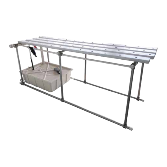
HydroCycle 6" Pro NFT Micro Lettuce System
System 115141 — 6" x 60" NFT Channels
©2021 Growers Supply
Designed to grow healthy plants without soil using mineral-nutrient solutions.
All Rights Reserved. Reproduction
is prohibited without permission.
*Actual system may differ from what is shown.
1
Revision date: 01.14.21
Advertisement

Subscribe to Our Youtube Channel
Related Manuals for FarmTek Growers Supply HydroCycle Lettuce Pro NFT


Summary of Contents for FarmTek Growers Supply HydroCycle Lettuce Pro NFT
- Page 1 HydroCycle 6" Pro NFT Micro Lettuce System System 115141 — 6" x 60" NFT Channels ©2021 Growers Supply Designed to grow healthy plants without soil using mineral-nutrient solutions. All Rights Reserved. Reproduction is prohibited without permission. *Actual system may differ from what is shown. Revision date: 01.14.21...
- Page 2 Important Information READ THIS DOCUMENT BEFORE YOU BEGIN Thank you for purchasing the 115141 6" NFT micro lettuce system. When properly assembled and maintained, this product will provide years of reliable service. These instructions include helpful hints and important information needed to safely assemble and properly maintain the system. Please read these instructions before you begin.
- Page 3 Important Information PICTORIAL GUIDE The following graphics and photos will help identify the different parts of the hydroponic system. (Some parts may not be shown.) To prevent mixing of fittings, select only those that are needed for each procedure. Keep all fittings in the shipping bags until they are needed. 111127 (4) 111698 Ratchet Clamp Plastic Pipe &...
- Page 4 Important Information PICTORIAL GUIDE (continued) 106808 & 112539 WG3840 111074 WF1023 Filter (1) 112066 (1) Shut- WF6682 WF3310 Hanger off to attach to WF1023 filter. 115820 WF1530 WF3411 WF1386 WF2990 and WF2153 WF2160 Grommets WF6717 Porthole Cover ATTENTION: Reservoir and lid style shown 20 Gallon Reservoir 20 Gallon Reservoir Cover throughout this guide may vary.
- Page 5 Assembly Instructions ASSEMBLE MAIN SUPPORT FRAME Consult Quick Start section near the back of this guide for additional diagrams and photos. Complete these steps to get started: 1. Place the two (2) base pipes (131P060) on a flat surface, slide three (3) tee fittings onto each 60"...
- Page 6 Assembly Instructions ASSEMBLE MAIN SUPPORT FRAME (continued) 3. With a metal-cutting saw or tool, cut the legs for the support frame. Use three (3) 131P072 pipes and cut as follows: — Two (2) legs at 33-1/2" — Two (2) legs at 34-3/4" —...
- Page 7 Assembly Instructions ASSEMBLE MAIN SUPPORT FRAME (continued) 6. With assistance, arrange and stand the two (2) base assemblies so leg lengths of each base assembly are aligned (i.e., 36" with 36", 34 3/4" with 34 3/4", and so on). It is best to construct support frame where it will be used so frame can be leveled for final assembly. 7.
- Page 8 Assembly Instructions LEVEL AND SQUARE THE MAIN FRAME Level and square the support frame before adding the NFT channels. An uneven frame can affect the delivery and distribution of the nutrient solution. Improper flow may cause irregular crop growth. The following procedure helps to ensure that channels will sit squarely on the frame. Complete these steps to level and square the main frame: Level End View...
- Page 9 Assembly Instructions ASSEMBLE ALL 5' 115143 CHANNELS 1. Using the assembled frame as a bench, place one 5' channel (115143) on cross supports. 2. Using 112509 adhesive, attach plain end cap (no outlet–111127) to channel end that is resting on high side of support table.
- Page 10 Assembly Instructions PREPARE THE 5' CHANNEL LIDS (115144) For this hydroponic system, channel lids ship without plant holes. Hole spacing and size varies depending on plants and growing medium. In this example, spacing for 1-3/8" holes is 8" on-center. Adjust hole size and spacing as needed for your growing medium and needs. 1.
- Page 11 Assembly Instructions PREPARE THE 5' CHANNEL LIDS (continued) For improved plant growth, off-set holes when installing lids. Alternate lids as shown below and on Nutrient Tube previous page. Before snapping lids onto channels, drill the nutrient tube holes at one end of each lid. Holes Complete these steps to drill holes for nutrient tubes: 1.
- Page 12 Assembly Instructions A. Position bottom of hanger ATTACH DRAIN MANIFOLD HANGERS TO FRAME 1" below bottom of tee fitting. Before assembly, dry fit all pvc connections before applying FA4470 (10) adhesive. Apply adhesive as instructed only. Tek Screw Use photos to the right to attach drain manifold mounting hangers to frame using FA4470 Tek screws and 100442 driver.
- Page 13 Assembly Instructions STEP 1 STEP 6 ASSEMBLE AND ATTACH PVC DRAIN MANIFOLD Complete these steps: Drain Manifold Assembly 1. Cut one 6" tube from the 2" pvc tube (111560Z5). Apply pvc primer and pvc cement to tube end and fitting. Slide into tee fitting. STEP 3 WF6717 Repeat to attach remaining section of pvc tubing to tee fitting.
- Page 14 Assembly Instructions Drill the 2-1/2" Drain Tube Hole 2-1/2" Drain DRILL HOLES IN RESERVOIR COVER Tube Hole Supply Drill the 2-1/2" Drain Tube Hole Tube Hole 1. Determine in which corner you want to drill the drain tube hole. This is the corner directly under the tee fitting outlet of the drain manifold.
- Page 15 Assembly Instructions ATTACH 1" HANGERS FOR NUTRIENT SUPPLY MANIFOLD FA4470B (10) Complete these steps: Tek Screw 1. Move to frame end opposite drain manifold. 2. Measure 7-1/2" in from each frame tee fitting and mark position on underside of crossbar. 106808 Hanger 3.
- Page 16 Assembly Instructions ASSEMBLE NUTRIENT SUPPLY MANIFOLD AND ATTACH TO FRAME Complete these steps: 1. Cut a piece of 3/4" pvc tube to fit between the leg pipes from a 10' section of WF4130 supplied with the system. WF2990 WF1530 2. Slide a WF1530 elbow onto one end of the 28" pipe and a WF2990 cap onto the other end. Do not cement at this time.
-
Page 17: Helpful Hint
Assembly Instructions DRILL HOLES TO INSTALL THE 115820 GROMMETS Step 2 Complete these steps: HELPFUL HINT: To maintain hole 1. Verify NFT channels are located in desired positions. alignment, along the 2. Using a marker, mark two (2) hole locations along the bottom side manifold pipe bottom side, snap a for each channel. - Page 18 Assembly Instructions FINISH MANIFOLD 1. Once all gromets are installed, apply pvc primer and cement to each end of the pvc supply manifold and inside elbow and cap and reinstall. Be sure to align the marks to install the elbow in the correct position. WF6990 PVC Cement &...
- Page 19 Assembly Instructions ASSEMBLE FILTER/VALVE, PUMP AND MAIN SUPPLY LINE 1. Take the 106808 hangers and attach two to the inside of the WR1095 FA4470B (10) crossbar at the drain end of the frame using the FA4470B Tek Tape Tek Screw screws.
- Page 20 Assembly Instructions ASSEMBLE PUMP AND MAIN SUPPLY LINE Using the photos on this page and the notes that follow, WF6504A 111074 111698 Ratchet install the water pump and main supply line. 3/4" Black Hose Clamp Read, understand, and follow these notes to construct the 110722 Utility Pump main supply line and pump assembly:...
- Page 21 Assembly Instructions CUT AND INSTALL THE SUPPLY TUBES 1. Determine the desired 1/4" tube length. Tube should reach from the grommet in the supply manifold to a hole in the channel lid immediately above the grommet. 2. Adjust tube length if needed and cut remaining tubes from the 111046 tube.
- Page 22 Assembly Instructions ATTENTION: Reservoir and lid style shown ATTENTION: Always position the air pump above the nutrient level to throughout this guide may vary. When needed, prevent siphoning of the reservoir. critical dimensions are noted for hole locations. ATTACH AIR PUMP AND AERATOR STONES 109260 Air For optimal system performance and to extend the life of nutrient solution through increased Stone...
- Page 23 Assembly Instructions INSTALL VERTICAL DRAIN TUBE AND FRAME CAPS Install the WF2995 pvc caps to cover the end of each open pipe. The vertical drain tube (A) directs the nutrient solution back to the tank. Use WF2995 the remainder of the first 111560Z5 tube if it is long enough to reach an inch or so through the cover and into the tank.
- Page 24 System Check System Check Column reserved for notes. After assembling the 115141 NFT system, take a few minutes to check the system. Complete these steps. 1. Verify all electrical cord ends are outside reservoir. 2. Ensure supply tubes are fully inserted in channel lids. 3.
- Page 25 OPERATIONAL AND MAINTENANCE INFORMATION Clean the Filter Screen and Housing General Cleaning and Maintenance Instructions For best results, clean the filter screen regularly or when the flow rate For optimal performance and to increase yields, check and clean the NFT changes unexpectedly.
- Page 26 OPERATIONAL AND MAINTENANCE INFORMATION RESERVOIR CLEANING AND MAINTENANCE Clean the reservoir periodically to maximize plant growth and to minimize system contamination. The steps that follow can be used to change nutrient solution and to pump the reservoir for cleaning and typical maintenance. Cleaning the filter is strongly recommended after cleaning the reservoir. 112066 Shutoff Valve...
- Page 27 115141 FRAME SUPPORT FRAME DIMENSIONS AND VIEWS 40" On-Center Cross Support 24" on-center 40" on-center 24" End View on-center 40" 6" On-Center on-center Ground Level Revision date: 01.14.21 115141...
- Page 28 ADDITIONAL PHOTOS NOTE: Actual system will have two supply lines per channel. Alternate channel styles for best growing results. Supply Manifold Photo shows the supply manifold and supply tubes of the NFT system. Drain Manifold Photo above shows a completed table as viewed from the drain end. Actual Photo shows a side view of a completed system.
- Page 29 ADDITIONAL PHOTO ATTENTION: Reservoir and lid style shown throughout this guide may vary. When needed, critical dimensions are noted for hole locations. Revision date: 01.14.21 115141...
- Page 30 PAGE RESERVED FOR CUSTOMER NOTES AND RECORDS 115141 Revision date: 01.14.21...
- Page 31 PAGE RESERVED FOR CUSTOMER NOTES AND RECORDS Revision date: 01.14.21 115141...
Need help?
Do you have a question about the Growers Supply HydroCycle Lettuce Pro NFT and is the answer not in the manual?
Questions and answers