
Related Manuals for Vents VUE2 150 P EC Comfo A6


Summary of Contents for Vents VUE2 150 P EC Comfo A6
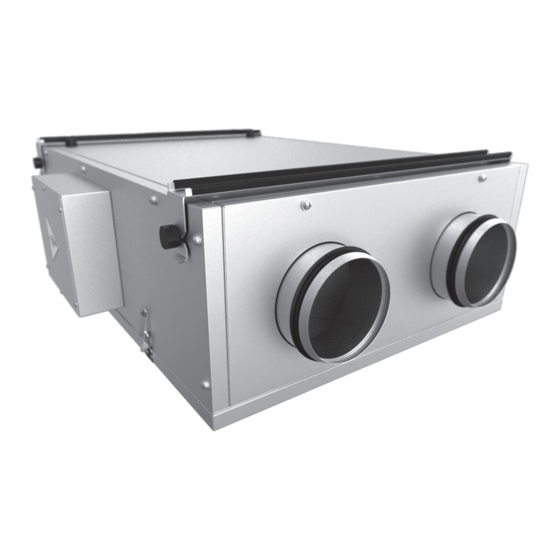
- Page 1 USER’S MANUAL VUE2 150 P EC Comfo A6 AIR HANDLING UNIT WITH HEAT AND ENERGY RECOVERY...
-
Page 2: Table Of Contents
CONTENTS Safety Requirements Introduction Delivery Set Designation Key Technical Data Design and Operating Logic Mounting and Setup Connection to Power Mains Unit Control Technical Maintenance Troubleshooting Transportation and Storage Regulations Manufacturer's Warranty Acceptance Certificate Seller's Information Mounting Certificate Warranty Card... -
Page 3: Safety Requirements
VUE2 150 P ЕС Comfo ТРЕБОВАНИЯ БЕЗОПАСНОСТИ • Read this user's manual carefully prior to the operation and installation of the air handling unit with heat and energy recovery, hereinafter the unit. • Installation and operation of the unit shall be performed in accordance with the present user's manual as well as the provisions of all the applicable local and national construction, electrical and technical codes and standards. - Page 4 UNIT OPERATION SAFETY PRECAUTIONS Do not touch the controller or the control Do not wash the unit with water. Avoid panel with wet hands. Do not carry out the unit penetration of water onto the electric parts maintenance with wet hands. of the unit.
-
Page 5: Introduction
This user's manual combines technical description, operation and service manual, technical data sheet and installation guidelines for the air handling unit with heat recovery VENTS VUE2150 P EC Comfo, hereinafter the unit. The unit is designed to ensure continuous mechanical air exchange in houses, offices, hotels, cafés, conference halls, and other utility and public spaces as well as to recover the heat energy contained in the air extracted from the premises to warm up the filtered stream of supply air. -
Page 6: Technical Data
TECHNICAL DATA The unit is designed for operation in an enclosed area at ambient temperatures from +5 ºС to + 40 ºС at relative humidity of up to 80%. In order to prevent condensation on the internal walls of the units, it is necessary that the surface temperature of the casing is 2-3 °C higher than the dew point temperature of the transported air. -
Page 7: Design And Operating Logic
VUE2 150 P ЕС Comfo Table 2. Control panel parameters Ambient temperature [°C] from 0 up to +40 Relative humidity [%] from 5 up to 90 (no condensation) Cable cross section [mm2] from 0.18 to 0.35 Material ABS plastic Dimensions (WхHхD) [mm] 86х86х14 Cable length [m] ... -
Page 8: Mounting And Setup
MOUNTING AND SETUP While installing the unit ensure convenient access for subsequent maintenance and repair. The unit is attached to the ceiling by means of two brackets secured to the ceiling with screws and dowels and four triangular yokes (the brackets and yokes are included in the delivery package), see Fig. -
Page 9: Connection To Power Mains
VUE2 150 P ЕС Comfo Fig. 4. Control panel installation CONNECTION TO POWER MAINS THE POWER MAINS CONNECTION SHALL ONLY BE PERFORMED BY QUALIFIED PERSONS AFTER CAREFUL STUDY OF THE PRESENT USER’S MANUAL. THE UNIT IS ONLY INTENDED FOR AC MAINS SUPPLYING THE VOLTAGE COMPLIANT WITH THE TECHNICAL PARAMETER TABLE. -
Page 10: Unit Control
Y - to the external air PK - to the re H - to the humidity damper alarm system (or CO2) sensor Damper actuator board “1” "2" Remove the jumper on connecting the “2” NC contact to the re alarm system. “3”... - Page 11 VUE2 150 P ЕС Comfo When the unit is off (Fig. 7) the control panel display indicates: Room temperature; Day; Time; Deactivated status Fig. 7. Panel display in the OFF mode When the unit is on (Fig. 8) the control panel display indicates: Room temperature;...
- Page 12 Unit Parameter Setup. CHANGING THE UNIT SETTINGS WILL DISCARD THE FACTORY SETTINGS! FAN SPEED CAN ONLY BE ADJUSTED FROM THE CONTROL PANEL! Fan Speed Setup Mode. At the setup stage each of the speed settings (Speed 1, Speed 2 and Speed 3) can be attributed a specific supply and exhaust fan performance.
- Page 13 VUE2 150 P ЕС Comfo In case of filter replacement alert switch off the unit by pressing the button and disconnect it from the power mains. Replace the filters (see the sequence given in the "Technical Maintenance" section, page 14). Connect the unit to the power mains and switch it on by means of the button on the control panel or the...
- Page 14 Entry number Time Fan speed Fig. 12. Scheduled operation setup mode indicators To select the scheduled operation setup mode parameters hold the button and use the buttons to make the selection as necessary. Use the buttons to set the parameter values. Scheduled operation setup mode parameters (Fig.
-
Page 15: Technical Maintenance
VUE2 150 P ЕС Comfo Alarms. In case of an emergency the unit switches off while the alarms are displayed on the control panel display screen, Fig. 13. The list of possible alarms is given in Table. 4. Freeze protection sensor triggering Freezing protection sensor breakout... - Page 16 ATTENTION! If the unit is mounted to the ceiling hold the service panel up while removing to avoid injuries. The lower part of the unit has a special retaining plate for convenient removal and replacement of the service panel (in case of the wall mounting). Fig.
-
Page 17: Troubleshooting
VUE2 150 P ЕС Comfo Fig. 15. Control unit maintenance TROUBLESHOOTING Table 5. Possible malfunctions and fault handling Problem Possible Reasons Fault handling Make sure that the unit is properly connected The fan (fans) will not start The unit is not connected to the power mains. to the power mains and make any corrections, if necessary. -
Page 18: Manufacturer's Warranty
MANUFACTURER'S WARRANTY The manufacturer hereby warrants normal operation of the unit over the period of 24 months from the retail sale date provided the user's observance of the transportation, storage, installation and operation regulations. Should any malfunctions occur during the unit operation through the manufacturer's fault during the warranty period the user is entitled to elimination of faults by means of warranty repair performed by the manufacturer. -
Page 19: Acceptance Certificate
VUE2 150 P ЕС Comfo ACCEPTANCE CERTIFICATE Product Type Air handling unit with heat and energy recovery Model VUE2150 P EC Comfo Serial Number Manufacturing Date is compliant with the technical specifications and is hereby declared ready for service. Quality Inspector's Stamp SELLER’S INFORMATION Address... -
Page 20: Warranty Card
WARRANTY CARD Product type Air handling unit with heat and energy recovery Model VUE2150 P EC Comfo Serial number Manufacturing date Sales date Warranty period Sales company Seller's seal NOTES ____________________________________________________________________________________ ____________________________________________________________________________________ ____________________________________________________________________________________ ____________________________________________________________________________________ ____________________________________________________________________________________ ____________________________________________________________________________________ ____________________________________________________________________________________ ____________________________________________________________________________________ ____________________________________________________________________________________ ____________________________________________________________________________________ ____________________________________________________________________________________ ____________________________________________________________________________________ ____________________________________________________________________________________... - Page 21 VUE2 150 P ЕС Comfo...
- Page 23 VUE2 150 P ЕС Comfo...
- Page 24 V94EN-04...
Need help?
Do you have a question about the VUE2 150 P EC Comfo A6 and is the answer not in the manual?
Questions and answers