Table of Contents
Advertisement
Quick Links
Questions, problems, missing parts? Before returning to the store,
8 a.m. - 7 p.m., EST, Monday - Friday, 9 a.m.- 6 p.m., EST, Saturday
We appreciate the trust and confidence you have placed in Home Decorators Collection through the purchase of this ceiling fan. We
strive to continually create quality products designed to enhance your home. Visit us online to see our full line of products available for
your home improvement needs. Thank you for choosing Home Decorators Collection!
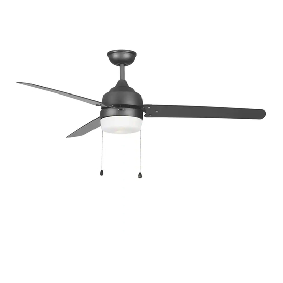
USE AND CARE GUIDE
CARRINGTON II 60 IN. CEILING FAN
call Home Decorators Collection Customer Service
1-800-986-3460
HOMEDEPOT.COM/HOMEDECORATORS
Visual instruction of how to install this fan:
Visit www.homedepot.com and enter either the Item or Model number to find
this fan and click the link of visual instruction in the product overview section.
THANK YOU
Item #1006 106 555
#1006 106 559
#1006 106 568
Model #YG419B-BN
#YG419B-NI
#YG419B-WH
Advertisement
Table of Contents

Related Manuals for Home Decorators Collection CARRINGTON II


Summary of Contents for Home Decorators Collection CARRINGTON II
- Page 1 THANK YOU We appreciate the trust and confidence you have placed in Home Decorators Collection through the purchase of this ceiling fan. We strive to continually create quality products designed to enhance your home. Visit us online to see our full line of products available for...
-
Page 2: Table Of Contents
Table of Contents Table of Contents ........Operation . -
Page 3: Safety Information
Safety Information used in accordance with the instructions, may cause harmful To reduce the risk of electric shock, ensure electricity has been interference to radio communications. turned off at the circuit breaker or fuse box before beginning. However, there is no guarantee that interference will not occur All wiring must be in accordance with the National Electrical in a particular installation. -
Page 4: Warranty
Warranty The manufacturer warrants the fan motor to be free from defects in workmanship and material present at time of shipment from the factory for a period of lifetime after the date of purchase by the original purchaser. The manufacturer warrants the light kit (excluding any glass), to be free from defects in workmanship and material present at time of shipment from the factory for a period of five years after the date of purchase by the original purchaser. -
Page 5: Hardware Included
Pre-Installation (continued) HARDWARE INCLUDED NOTE: Hardware not shown to actual size. Part Description Quantity Plastic wire nut Blade attachment screw and fiber washer 9 Watt LED medium base bulb Pull chain and fob HOMEDEPOT.COM/HOMEDECORATORS Please contact 1-800-986-3460 for further assistance. -
Page 6: Package Contents
Pre-Installation (continued) PACKAGE CONTENTS Part Description Quantity Part Description Quantity Mounting bracket (preassembled) Blade arm Canopy ring (preassembled) Blade Canopy Medallion Hanger ball/downrod assembly Switch housing Coupling cover Light kit Fan motor assembly Plastic shade... -
Page 7: Installation
Installation MOUNTING OPTIONS WARNING: To reduce the risk of fire, electric shock, or NOTE: You may need a longer downrod to maintain proper personal injury, mount the fan to an outlet box marked blade clearance when installing on a steep, sloped ceiling. acceptable for fan support using the screws provided with the The maximum angle allowable is 18°... -
Page 8: Assembly
Assembly Preparing the canopy Preparing the motor Remove the canopy ring (B) from the canopy (C). Remove the cotter pin (FF) and clevis pin (GG), and loosen the two collar setscrews (HH) from the motor collar. Remove the two non-slotted canopy mounting screws with Take out the setscrew (II) located in the hanger ball (JJ), lock washers (EE) from the canopy (C), and loosen the lower the hanger ball (JJ) and remove the cross pin (KK). -
Page 9: Hanging The Fan
Assembly — Hanging the Fan Installing the mounting bracket Hanging the fan to the mounting to the electrical box bracket WARNING: To reduce the risk of fire, electric shock or WARNING: The tab in the ring must rest in the groove of the hanger ball/downrod assembly (D). - Page 10 Assembly — Hanging the Fan (continued) Making the electrical connections Ground WARNING: To avoid possible electrical shock, be sure conductor Neutral electricity is turned off at the main fuse box before wiring. Black White WARNING: Check to see that all connections are tight, including ground, and that no bare wire is visible at the wire nuts, except for the ground wire.
- Page 11 Assembly — Hanging the Fan (optional) Single Switch Connections Dual Switch Connections On a single switch the fan and light can be turned on or off On a dual switch the fan and light can be turned on or off together.
- Page 12 Assembly — Hanging the Fan (continued) Installing the canopy WARNING: Make sure the tab on the mounting bracket (A) Outlet Box properly sits in the groove in the hanger ball/downrod assembly (D) before attaching the canopy (C) to the mounting bracket (A) by turning the canopy (C) until it drops into place.
-
Page 13: Attaching The Fan Blades
Assembly — Attaching the Fan Blades Attaching the blades to the blade Removing the rubber packing mounts arms The fan motor assembly (F) is shipped with rubber Attach the blades (H) to the blade arms (G) using the three packing mounts (NN) to prevent movement during blade attachment screws and fiber washers (BB) and the transportation. -
Page 14: Installing The Light Kit
Assembly — Installing the Light Kit Attaching the switch housing to Attaching the light kit to the the mounting ring switch housing Remove one of the three light kit mounting screws (SS) from CAUTION: Before starting installation, disconnect the the switch housing (J) and loosen the other two screws (SS). power by turning off the circuit breaker or removing the fuse (Do not remove.) at the fuse box. - Page 15 Assembly — Installing the Light Kit (continued) Installing the light bulbs Installing the Plastic shade Position the notches (UU) in the outer rim of the plastic CAUTION: Before starting installation, disconnect the shade (L) so they line up with the tabs (VV) on the inside of power by turning off the circuit breaker or removing the fuse the rim on the light kit (K).
-
Page 16: Operation
Operation PULL CHAIN OPERATING INSTRUCTIONS Install the pull chains and fobs (DD) onto the pull chains located in the switch housing (J). Turn on the power and check the operation of the fan. The pull chain controls the fan speed as follows: 1 pull - High, 2 pulls - Medium, 3 pulls - Low, and 4 pulls - Off. -
Page 17: Care And Cleaning
Care and Cleaning Do not Check the support connections, brackets, and blade Use water when cleaning. Water could damage the motor, attachments twice a year. Make sure they are secure. or the wood, or possibly cause an electrical shock. Because of the fan’s natural movement, some connections may become loose over time. - Page 18 Troubleshooting (continued) Problem Solution Verify that all blades and blade bracket screws are secure (most fan wobble problems are caused by loose parts). Once the fan is properly installed, run the ceiling fan for 10 minutes to let the fan self-adjust.
-
Page 19: Service Parts
Service Parts Description Part Description Part Mounting bracket (preassembled) Plastic wire nut Canopy ring (preassembled) Blade attachment screw and rubber washer Canopy 9 Watt LED medium base bulb Hanger ball/downrod assembly Pull chain and fob Coupling cover Fan motor assembly Blade arm Blade Medallion... - Page 20 Questions, problems, missing parts? Before returning to the store, call Home Decorators Collection Customer Service 8 a.m. - 7 p.m., EST, Monday - Friday, 9 a.m.- 6 p.m., EST, Saturday 1-800-986-3460 HOMEDEPOT.COM/HOMEDECORATORS Retain this manual for future use.
Need help?
Do you have a question about the CARRINGTON II and is the answer not in the manual?
Questions and answers