
Related Manuals for Ofs 432


Summary of Contents for Ofs 432
- Page 1 Issue2 November 14, 2011 432 Outdoor Fiber Distribution Cabinets Installation Manual - 0 -...
- Page 2 The contents of this document as of the date of publication are current. OFS reserves the right to change the contents without prior notice. OFS in no way will be liable for any damages resulting from loss of information, use or profits. OFS further disclaims all liability direct or indirect, consequential or incidental for all product, publications and services during and after the warranty period.
-
Page 3: Table Of Contents
Issue2 November 14, 2011 TABLE OF CONTENTS About this Manual Product Overview Product Specifications Warnings Inspecting Shipment Replacement and Accessory Kits Installation Pole Mounting Pad Installation Grounding Fiber Routing Customer Information and Assistance - 2 -... -
Page 4: About This Manual
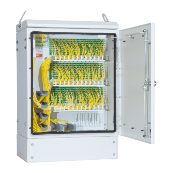
Product Overview The 432 Outdoor FDC is available in a 432 port configurations. The 432 FDC cabinet can either be pad mounted or pole mountable outdoor. The 432 FDC cabinet has overall dimensions of 36 inches in height, 18 inches in depth, and 24 inches in width (Figure 4). - Page 5 Issue2 November 14, 2011 Figure 3: Front View of Cabinet The front section houses fiber optic equipment and is provided with 23” wide rack space. The rear section is used for cable ingress and egress. Cable entry and exit from the cabinet passes through the split seals located in the bottom rear section of the equipment bay.
-
Page 6: Product Specifications
Issue2 November 14, 2011 Product Specifications 432 Fiber Distribution Cabinet Figure 4: Rear view of cabinet showing rear panel - 5 -... -
Page 7: Warnings
Check the packing list to ensure complete and accurate shipment of all listed items. If the packing list is irregular or deficient in any way, please contact OFS as described in the Warranty agreement. Prolonged storage of the equipment should be done the original container. -
Page 8: Installation
Seal, 2 port, cable entry Door Latch Installation Manual Table 1: Replacement and Accessory Kit Contents Installation Instructions 432 Outdoor Fiber Distribution Cabinet can be pole mounted or pad mounted. Pole Mounting Figure 6: Pole Mounting Diagram - 7 -... - Page 9 Issue2 November 14, 2011 Table 2: Pole Mounting Kit Bill of Materials Figure 7: Dimensions for Pole Mounting - 8 -...
- Page 10 Issue2 November 14, 2011 Pole Mounting Installation Procedures Use this procedure to mount the cabinet on an 8 to 14 inch diameter wooden pole. See figures 6 and 7 on previous pages. Have the following equipment ready before beginning this procedure: One drill One ¾”...
-
Page 11: Pad Installation
12. If the cable stubs connect to an underground cable, dress the cable down the pole. If the cable stubs connect to an aerial cable, form a drip loop in the cable and dress it up the pole to the splice case. Pad Installation Figure 8: 432 Cabinet Mounting Template - 10 -... - Page 12 (from the top view). Figure 10: Cabinet Footprint The 432 Fiber Distribution Cabinet does not require the threading of input and output cables through the base of the cabinet. The cable entry area can be found at the rear of the cabinet.
- Page 13 Issue2 November 14, 2011 Figure 11: Cable Entry Area, Rear View Figure 12: Top View of Cable Entry Area - 12 -...
- Page 14 Issue2 November 14, 2011 Pad Installation Procedures Have the following equipment ready before beginning this procedure: 1. One masonry drill 2. One 5/8” (15.9 mm) masonry drill bit 3. Masonry expansion anchors 4. One 9/16” wrench 5. A pencil 6. One Hammer Use the procedure below to mount the cabinet on an existing concrete slab.
-
Page 15: Grounding
Issue2 November 14, 2011 Cabinet Grounding Information Bonding and grounding should be done in accordance with the operating telephone company’s standard procedures and comply with local electrical codes. Ground Wire The ground wire protects the electronics from voltage surges. A #6 ground wire must be properly grounded to provide lightning surge protection for the cabinet. - Page 16 Issue2 November 14, 2011 Installation Procedures Figure 13: Grounding Diagram To ground the cabinet, use the following procedures and diagram above (Figure 13): 1. Drive the ground rods into the ground near the cabinet location. 2. Use a Megger-type Ohmeter to measure the resistance between the cabinet ground and the ground rods.
-
Page 17: Fiber Routing
Fiber Routing Fiber Pass Trough Parking 432 Fiber Distribution Cabinet – Fiber routing Fig. 14 When routing the pigtails optimize the cable slack by choosing appropriate bend control guides. Avoid cable kinking and pulling during the installation. Use the shelves and the rings for keeping the pigtails organized. -
Page 18: Customer Information And Assistance
1-888-342-3743, Prompt 2 Technical Support 1-888-342-3743, Prompt 3 Please feel free to contact your Customer Service Representative for any product related issues. Please make available OFS order number, part numbers, and company information at the time of contact. - 17 -...
Need help?
Do you have a question about the 432 and is the answer not in the manual?
Questions and answers