Table of Contents
Advertisement
Quick Links
TERMINA
TR 611 top2 RC
611 0 300
Installation and
operating instructions
Time switch
D GB
F
I
E
P
NL
PL
Ext
L
N
RC
theben
0
6
12
18
24
MENU
OK
2
0,5mm -
2
2,5mm
230-240V~
50-60Hz
16(10)A 250V~
R 10a - 30T
C1
1
2
3
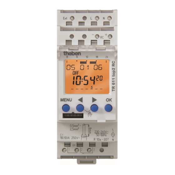
TERMINA 611 top2 RC
Correct connection required for smooth zero
crossing switch operation (see connection diagram)!
309 280 01
max. 100 m
Separate phases
can be connected!
GB
Advertisement
Table of Contents

Related Manuals for Theben TERMINA TR 611 top2 RC


Summary of Contents for Theben TERMINA TR 611 top2 RC
- Page 1 309 280 01 TERMINA TR 611 top2 RC 611 0 300 theben Installation and operating instructions MENU Time switch max. 100 m 0,5mm - 2,5mm 230-240V~ 50-60Hz 16(10)A 250V~ R 10a - 30T D GB Separate phases can be connected!
-
Page 2: Table Of Contents
Contents Basic advice Screen and keys Overview of menu selection Connection/installation Initial start-up Menu item PROGRAM Set switching time Change/delete switching time (applies also for pulse and cycle) Pulse programming Cycle programming RESET Menu item MANUAL Manual and permanent switching Menu item OPTIONS PIN code setting External output... -
Page 3: Basic Advice
Basic safety instructions WARNING Danger of death through electric shock or fire! Installation should only be carried out by professional electrician! • The device is designed for installation on DIN top hat rails (in accordance with EN 60715) • Corresponds to type 1 BSTU in accordance with IEC/EN 60730-2-7 •... -
Page 4: Screen And Keys
Screen display and keys Operating instructions Programmed 1. Read text line Display DCF antenna switch times Flashing text/symbol connected represents query Date display Time display Channel status Days of the week from ON = On 1 to 7 2. Make a decision OFF = Off Display of active keys withrelevant function... -
Page 5: Overview Of Menu Selection
Overview of menu selection MENU 19 10 PROGRAM TIME/DATE MANUAL OPTIONS 9:40 TIME OPERATING PERMA- HOURS METER NENT ON DATE VIEW PERMA- EXTERNAL OUTPUT NENT OFF CHANGE MANUAL LCD ILLUMI- SUMMER-- NATION WINTER DELETE LANGUAGE DAY OF THE TIMER WEEK... -
Page 6: Connection/Installation
Connection/installation WARNING Warning, danger of death through electric shock! Must be installed by professional electrician! Connect power source. Cover or shield any adjacent live components. Ensure device cannot be switched on! 45° cable Check power supply is disconnected! ... -
Page 7: Initial Start-Up
Initial start-up GERMAN DATE FORMAT Set date, time and YEAR summer/winter time rule MONTH P ress any key and follow on-screen TIME FORMAT instructions (see fig.). HOUR SUMMER-WIN- 19 10 07 MINUTE TER GB/ IRL/P You can connect top2 RC-DCF antenna 9:40 SUMMER- SUMMER-WINTER... -
Page 8: Set Switching Time
Set switching time Press MENU. PROGRAM SWITCHING (see picture) TIME FREE 84 84 memory locations are available. HOUR MINUTE MONDAY same switching time for Switching several days = block time for COPY SAVE one day PLUS TUESDAY SAVE... -
Page 9: Change/Delete Switching Time (Applies Also For Pulse And Cycle)
Change/delete switching time (applies also for pulse and cycle) Press MENU. PROGRAM (see fig.) VIEW CHANGE SWITCHING MONDAY TIME DELETE. CHANGE You can either change or delete a block, HOUR i.e. a switching time copied for several days CHANGE MINUTE (e.g. -
Page 10: Pulse Programming
Pulse programming PROGRAM SWITCHING TIME (for pause signals, air-conditioning, PULSE FREE 84 flushing etc.) CYCLE HOUR Press MENU (see picture). MINUTE SECONDS PULSE DURA- TION MINUTE SECONDS MONDAY COPY SAVE PLUS TUESDAY SAVE... -
Page 11: Cycle Programming
Cycle programming PROGRAM (with cyclical time functions, SWITCHING e. g. watertreatment etc.) TIME PULSE Press MENU (see picture). CYCLE FREE 84 START CYCLE HOUR MINUTE MONDAY PULSE RESET DURATION PAUSE Press the 4 buttons simultaneously. You can choose between KEEP WITH END CONTINUOUS PROGRAM and DELETE PROGRAM. -
Page 12: Manual And Permanent Switching
The PIN code can be set using the OPTIONS menu item (see fig.). If you forget the PIN call- Manual and permanent switching can be set the Theben hotline. using the menu in MANUAL or (in the auto- matic screen) by key combination (see fig.). -
Page 13: External Output
External output OBELISK top2 memory card The EXTERNAL INPUT is set via the menu in Use memory card (see fig.) OPTIONS (see fig.). Insert memory card in the timer. Use key/switch without glow lamp. Request savedswitch timings, read to/from the timer or start Obelisk program. -
Page 14: Dcf Reception With Top2 Rc-Dcf Antenna
Time signal can be received with appropriate top2 RC antenna Example The top2 RC-DCF antenna (907 0 410) can be connected to the TERMINA 611 top2 RC time switch. The TERMINA 611 top2 RC time switch can only be connected to the top2 RC–DCF antenna. - Page 15 A maximum of 10 devices can be connected to one antenna. Setting time zones After successful synchronisation, the time zone can be altered in the TIME/DATE menu option. theben In the TIME menu option (Indicating: ALTER HOUR) correct the applicable local time (time zone). MENU...
-
Page 16: Technical Data/Service Address/Hotline
R 8a - 30T If the switch output is 230 V, the time switch can be operated using low function voltage but not SELV as Serviceadresse supply voltage. Theben AG 12 - 24 V 12 - 24 V Hohenbergstr. 32 ...
Need help?
Do you have a question about the TERMINA TR 611 top2 RC and is the answer not in the manual?
Questions and answers