Table of Contents
Advertisement
Quick Links
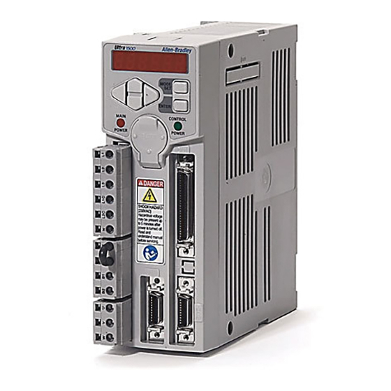
Ultra1500 Digital Drives
(Catalog Numbers 2092-DA1, 2092-DA2, 2092-DA3, 2092-DA4, and 2092-DA5)
This Quick Start guide provides the basic information for installing and verifying the
operational status of an Ultra1500™ with a compatible motor. This Quick Start is intended
for qualified drive service personnel only.
For detailed and application related information about Ultra1500 drives, refer to the on-line
help provided with v1.60 or higher of Ultraware™ software (catalog number 2098-UWCPG)
and the Ultra1500 Digital Drive User Manual (publication 2092-UM001x-EN-E).
Set up your drive as easy as:
•
Wire the drive.
•
Configure using the Setup Wizard in Ultraware.
•
Spin the motor.
Important User Information
Because of the variety of uses for the products described in this publication, those responsible
for the application and use of this control equipment must satisfy themselves that all
necessary steps have been taken to assure that each application and use meets all performance
and safety requirements, including any applicable laws, regulations, codes and standards.
The illustrations, charts, sample programs and layout examples shown in this guide are
intended solely for purposes of example. Since there are many variables and requirements
associated with any particular installation, Allen-Bradley
liability (to include intellectual property liability) for actual use based upon the examples
shown in this publication.
Allen-Bradley publication SGI-IN001A-EN-P, Safety Guidelines for the Application, Installation
and Maintenance of Solid-State Control (available from your local Allen-Bradley office), describes
some important differences between solid-state equipment and electromechanical devices
that should be taken into consideration when applying products such as those described in
this publication.
Unpacking Your Ultra1500 Digital Drive
The box contains the following:
•
One Ultra1500 drive (catalog numbers are listed above),
•
Three removable plugs mounted on the power connectors of the drive,
•
One connector tool for opening wire clamps on power connectors, and
•
This Quick Start document.
®
does not assume responsibility or
Publication 2092-QS001D-EN-P — July 2005
Quick Start
Advertisement
Table of Contents


Need help?
Do you have a question about the Ultra1500 and is the answer not in the manual?
Questions and answers