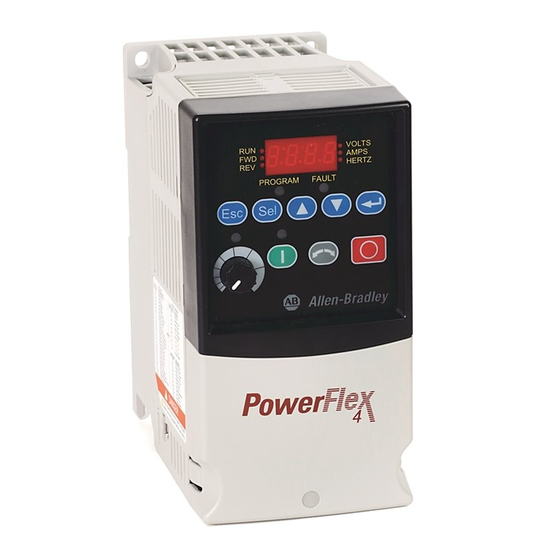
Allen-Bradley PowerFlex 4 Quick Start Manual
Adjustable frequency ac drive
Hide thumbs
Also See for PowerFlex 4:
- Quick start manual ,
- User manual (108 pages) ,
- Original instructions manual (39 pages)
Table of Contents
Advertisement
Quick Links
All manuals and user guides at all-guides.com
PowerFlex 4 Adjustable
Frequency AC Drive
FRN 2.xx
This Quick Start guide summarizes the basic steps needed to install,
start-up and program the PowerFlex 4 Adjustable Frequency AC Drive.
The information provided Does Not replace the User Manual and is
intended for qualified drive service personnel only.
For detailed PowerFlex 4 information including EMC instructions,
application considerations and related precautions refer to the
PowerFlex 4 User Manual, Publication 22A-UM001x on the CD
supplied with the drive or at
General Precautions
ATTENTION: The drive contains high voltage capacitors which take
time to discharge after removal of mains supply. Before working on
!
drive, ensure isolation of mains supply from line inputs [R, S, T (L1,
L2, L3)]. Wait three minutes for capacitors to discharge to safe voltage
levels. Failure to do so may result in personal injury or death.
Darkened display LEDs is not an indication that capacitors have
discharged to safe voltage levels.
ATTENTION: Equipment damage and/or personal injury may result
!
if this parameter (A092 [Auto Rstrt Tries], A094 [Start At PowerUp]) is
used in an inappropriate application. Do not use this function without
considering applicable local, national and international codes,
standards, regulations or industry guidelines.
ATTENTION: Only qualified personnel familiar with adjustable
frequency AC drives and associated machinery should plan or
!
implement the installation, start-up and subsequent maintenance of the
system. Failure to comply may result in personal injury and/or
equipment damage.
ATTENTION: This drive contains ESD (Electrostatic Discharge)
sensitive parts and assemblies. Static control precautions are required
!
when installing, testing, servicing or repairing this assembly.
Component damage may result if ESD control procedures are not
followed. If you are not familiar with static control procedures,
reference A-B publication 8000-4.5.2, "Guarding Against Electrostatic
Damage" or any other applicable ESD protection handbook.
ATTENTION: An incorrectly applied or installed drive can result in
component damage or a reduction in product life. Wiring or application
!
errors, such as, undersizing the motor, incorrect or inadequate AC
supply, or excessive ambient temperatures may result in malfunction of
the system.
www.ab.com/manuals/dr.
Quick Start
Advertisement
Table of Contents

Related Manuals for Allen-Bradley PowerFlex 4


Summary of Contents for Allen-Bradley PowerFlex 4
- Page 1 FRN 2.xx This Quick Start guide summarizes the basic steps needed to install, start-up and program the PowerFlex 4 Adjustable Frequency AC Drive. The information provided Does Not replace the User Manual and is intended for qualified drive service personnel only.
-
Page 2: Mounting Considerations
Use Mounting Option B 50°C (122°F) IP 20/Open Type Use Mounting Option B Rating requires installation of the PowerFlex 4 IP 30/NEMA 1/UL Type 1 option kit. General Grounding Requirements Important: Remove the MOV to ground jumper if the drive is installed on an ungrounded distribution system. - Page 3 Faultless Power Ride Through: 100 milliseconds Dynamic Braking Internal brake IGBT included with all ratings 0.75 kW (1 HP) and larger. Refer to Appendix B of the PowerFlex 4 User Manual on CD for ordering information. 200-240V AC - 1-Phase drives are also available with an integral EMC filter. Catalog suffix changes from N104 to N114.
-
Page 4: Power Wiring
Remove MOV jumper to ground. • and Install Isolation Transformer with Ungrounded Distribution System grounded secondary if necessary. Refer to Appendix B of the PowerFlex 4 User Manual on CD for accessory ordering information. I/O Wiring Recommendations Wire Type(s) Description Minimum Insulation Rating Belden 8760/9460 0.8 mm... -
Page 5: Control Terminal Block
All manuals and user guides at all-guides.com English-5 Control Terminal Block Refer to the PowerFlex 4 Important: I/O Terminal 01 is P036 I/O Terminal 01 User Manual on CD for [Start Source] always a coast to stop input except Stop Stop detailed I/O wiring examples. -
Page 6: Prepare For Drive Start-Up
Important: To disable reverse operation, see A095 [Reverse Disable]. If a fault appears on power up, refer to page 11 for an explanation of the fault code. For complete troubleshooting information, refer to the PowerFlex 4 User Manual on the CD supplied with the drive. -
Page 7: Integral Keypad
All manuals and user guides at all-guides.com English-7 Integral Keypad — – ˜ Menu Description VOLTS Display Group (View Only) AMPS HERTZ Consists of commonly viewed drive operating conditions. PROGRAM FAULT ™ š Basic Program Group Consists of most commonly used programmable functions. -
Page 8: Viewing And Editing Parameters
All manuals and user guides at all-guides.com English-8 Viewing and Editing Parameters The last user-selected Display Group parameter is saved when power is removed and is displayed by default when power is reapplied. The following is an example of basic integral keypad and display functions. This example provides basic navigation instructions and illustrates how to program the first Program Group parameter. - Page 9 See the PowerFlex 4 User Manual on CD for more information on parameters. Smart Start-Up with Basic Program Group Parameters The PowerFlex 4 is designed so that start up is simple and efficient. The Program Group contains the most commonly used parameters.
- Page 10 All manuals and user guides at all-guides.com English-10 See the PowerFlex 4 User Manual on CD for more information on parameters. Parameter Min/Max Display/Options Default A070 [Preset Freq 0] 0.0/240.0 Hz 0.1 Hz 0.0 Hz A071 [Preset Freq 1] 5.0 Hz...
-
Page 11: Display Group Parameters
All manuals and user guides at all-guides.com English-11 See the PowerFlex 4 User Manual on CD for more information on parameters. Display Group Parameters Parameter Min/Max Display/Options d001 [Output Freq] 0.0/[Maximum Freq] 0.1 Hz d002 [Commanded Freq] 0.0/[Maximum Freq] 0.1 Hz 0.00/Drive Amps ×... -
Page 12: Drive Dimensions
2.2 (4.9) Overall height of drive with IP 30/NEMA 1/UL Type 1 option kit installed. Overall height of standard IP 20/Open Type drive. PowerFlex 4 Frames – Ratings are in kW and (HP) Frame 120V AC – 1-Phase 240V AC – 1-Phase 240V AC –...
Need help?
Do you have a question about the PowerFlex 4 and is the answer not in the manual?
Questions and answers