Table of Contents
Advertisement
Quick Links
Advertisement
Table of Contents

Subscribe to Our Youtube Channel
Related Manuals for Metrohm 6.2841.120


Summary of Contents for Metrohm 6.2841.120
- Page 1 Liquid Handling Station Manual 8.108.8011EN...
- Page 3 Metrohm AG CH-9100 Herisau Switzerland Phone +41 71 353 85 85 Fax +41 71 353 89 01 info@metrohm.com www.metrohm.com Liquid Handling Station Manual 8.108.8011EN 05.2013 fpe...
- Page 4 Teachware Metrohm AG CH-9100 Herisau teachware@metrohm.com This documentation is protected by copyright. All rights reserved. Although all the information given in this documentation has been checked with great care, errors cannot be entirely excluded. Should you notice any mistakes please send us your comments using the address given above.
-
Page 5: Table Of Contents
General notes ..............18 4.1.1 Care ..................18 4.1.2 Maintenance by Metrohm Service .......... 18 Quality Management and qualification with Metrohm . . 19 5 Technical specifications Magnetic stirrer ..............20 Power supply ..............20 Interfaces and connectors ..........20 Ambient temperature ............ - Page 6 ■■■■■■■■■■■■■■■■■■■■■■ Table of contents Optional accessories ............26 7.2.1 Liquid Handling Station ............26 Index ■■■■■■■■...
- Page 7 ■■■■■■■■■■■■■■■■■■■■■■ Table of figures Table of figures Figure 1 Overview of the instrument Liquid Handling Station (left-handed ver- sion) ....................5 Figure 2 Removing the mixing vessel ............... 7 Figure 3 Removing the holding mechanism ............. 7 Figure 4 Removing the magnetic stirrer dummy ..........8 Figure 5 Removing the clamping fastener ............
-
Page 9: Introduction
The Liquid Handling Station can be combined with sample changers equipped with a robotic arm. Depending on the swing direction, either the left-handed (6.2841.120) or the right-handed (6.2841.130) version of the Liquid Handling Station is used. The Liquid Handling Station consists of two function units: Rinsing unit The rinsing unit is equipped with a two-pipe system. -
Page 10: Symbols And Conventions
■■■■■■■■■■■■■■■■■■■■■■ 1.2 About the documentation 1.2.1 Symbols and conventions The following symbols and formatting may appear in this documentation: Cross-reference to figure legend The first number refers to the figure number, the sec- ond to the instrument part in the figure. Instruction step Carry out these steps in the sequence shown. -
Page 11: Safety Instructions
The electrical safety when working with the instrument is ensured as part of the international standard IEC 61010. WARNING Only personnel qualified by Metrohm are authorized to carry out service work on electronic components. WARNING Never open the housing of the instrument. The instrument could be damaged by this. -
Page 12: Flammable Solvents And Chemicals
■■■■■■■■■■■■■■■■■■■■■■ 1.3 Safety instructions Protection against electrostatic charges WARNING Electronic components are sensitive to electrostatic charges and can be destroyed by discharges. Do not fail to pull the mains cable out of the mains connection socket before you set up or disconnect electrical plug connections at the rear of the instrument. -
Page 13: Overview Of The Instrument
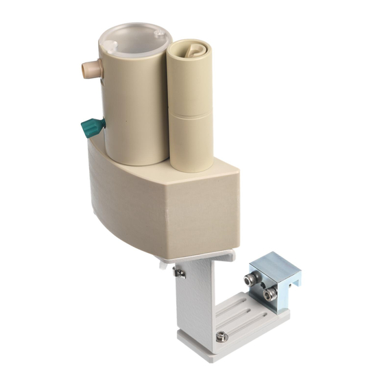
■■■■■■■■■■■■■■■■■■■■■■ 2 Overview of the instrument 2 Overview of the instrument Liquid Handling Station in the left-handed version, complete with attach- ment holder for assembly on a sample changer. Figure 1 Overview of the instrument Liquid Handling Station (left- handed version) Cover for mixing vessel Mixing vessel Mixing vessel connector - UNF 10/32... -
Page 14: Installation
If the Liquid Handling Station is to be used for dilutions, then it must be converted. The following instruments are required for this purpose: Liquid Handling Station ■ – Left-handed version, 6.2841.120 – Right-handed version, 6.2841.130 Magnetic stirrer, 2.741.0010 ■ CAUTION Use caution and do not apply excessive force when carrying out the fol- lowing procedures. -
Page 15: Figure 2 Removing The Mixing Vessel
■■■■■■■■■■■■■■■■■■■■■■ 3 Installation Figure 2 Removing the mixing vessel 2 Unscrew the three screws connecting the main body with the sup- port bracket and remove the entire holding mechanism. Figure 3 Removing the holding mechanism 3 Unscrew the two screws on the base of the main body and pull out the magnetic stirrer dummy. -
Page 16: Figure 4 Removing The Magnetic Stirrer Dummy
■■■■■■■■■■■■■■■■■■■■■■ 3.1 Preparing the Liquid Handling Station Figure 4 Removing the magnetic stirrer dummy Preparing the magnetic stirrer 1 Unscrew the two screws of the magnetic stirrer (2.741.0010) and remove the clamping fastener. The clamping fastener is no longer used in this application. Figure 5 Removing the clamping fastener Installing the magnetic stirrer... -
Page 17: Figure 7 Tightening The Magnetic Stirrer
■■■■■■■■■■■■■■■■■■■■■■ 3 Installation 2 Insert the two screws and tighten them. Figure 7 Tightening the magnetic stirrer 3 Place the previously removed holding mechanism against the main body and connect the two parts with the three screws. Figure 8 Screwing on the holding mechanism 4 Mount the mixing vessel and press it all the way down. -
Page 18: Figure 9 Attaching The Mixing Vessel
■■■■■■■■■■■■■■■■■■■■■■ 3.1 Preparing the Liquid Handling Station Figure 9 Attaching the mixing vessel 5 Fixing the connection cable in place with the cable clip. NOTE Ensure that no damage is caused to the connection cable from crushing. Figure 10 Fixing the connection cable in place ■■■■■■■■... -
Page 19: Mounting The Liquid Handling Station
■■■■■■■■■■■■■■■■■■■■■■ 3 Installation Mounting the Liquid Handling Station The Liquid Handling Station requires precise mounting and alignment in order to function properly with the entire system. CAUTION Faulty, imprecise assembly The components could become damaged during operation if assembled in a faulty and imprecise manner. Observe the assembly sequence. -
Page 20: Figure 12 Distance To Sample Rack
■■■■■■■■■■■■■■■■■■■■■■ 3.2 Mounting the Liquid Handling Station Placing the Liquid Handling Station on the guide 1 Attach the Liquid Handling Station to the assembly rail (11-4) with the clamping fastener (11-3). 2 Secure the Liquid Handling Station temporarily in place with the screw (11-2). -
Page 21: Figure 13 Positioning The Liquid Handling Station
■■■■■■■■■■■■■■■■■■■■■■ 3 Installation Aligning the Liquid Handling Station with the retaining plate 1 Loosen the screw (11-2) on the clamping fastener. 2 Slide the entire Liquid Handling Station that is on the assembly rail under the retaining plate in the direction of the arrow (see Figure 14, page 14) (14-1). -
Page 22: Defining Work Positions
■■■■■■■■■■■■■■■■■■■■■■ 3.3 Defining work positions Figure 14 Alignment with the retaining plate Sample tube swing range 3 Retighten the screw (11-2) on the clamping fastener. 4 Check whether the distance to the sample rack is consistent with Fig- ure 12 and whether the position in relation to the retaining plate (see Figure 14, page 14) is suitable. -
Page 23: Figure 15 External Position - Guidelines
■■■■■■■■■■■■■■■■■■■■■■ 3 Installation NOTE Value settings of the angles External position These value settings are guidelines that may need to be corrected when the Liquid Handling Station is set up. Figure 15 External position - Guidelines External position 1 External position 2 External position 3 External position 4 NOTE... -
Page 24: Figure 16 External Positions
■■■■■■■■■■■■■■■■■■■■■■ 3.3 Defining work positions 3 + 4 Figure 16 External positions Rinsing unit - Rinse Rinsing unit - Disposal Dilution unit Dilution unit (standard depth) CAUTION Damage to the sample tube The External position 3 also has to be set in order to avoid a collision in case it is used. -
Page 25: Figure 18 Working Range - Disposal
■■■■■■■■■■■■■■■■■■■■■■ 3 Installation 3 If necessary, correct the angle value. 4 Move to External position 2 (16-2). 5 Check whether the sample tube is centered over the "Rinsing unit - Disposal" position. Figure 18 Working range - Disposal 6 If necessary, correct the angle value. 7 Move to External position 3 + 4 (16-3), (16-4). -
Page 26: Operation And Maintenance
Metrohm Service is to be informed in the event of this kind of damage. -
Page 27: Quality Management And Qualification With Metrohm
Maintenance The electronic and mechanical functional groups of Metrohm instruments can and should be checked by specialist personnel from Metrohm as part of a regular preventive maintenance schedule. Please ask your local Metrohm representative regarding the precise terms and conditions involved in concluding a corresponding maintenance agreement. -
Page 28: Technical Specifications
■■■■■■■■■■■■■■■■■■■■■■ 5.1 Magnetic stirrer 5 Technical specifications Magnetic stirrer Shift direction Counterclockwise Rotational speed 200 - 1,900 rpm Power supply Power supply 5 - 12 V DC ≤ 4.0 W Power consump- tion Interfaces and connectors The Liquid Handling Station does not have any control interfaces. It is operated and controlled via the power supply. -
Page 29: Dimensions/Material
■■■■■■■■■■■■■■■■■■■■■■ 5 Technical specifications Dimensions/material Width 131 mm Height 94 mm Depth 224 mm Weight 660 g (without accessories) Material Mixing vessel/ rinsing unit Holder Aluminum sheet, stove-enameled Volume Mixing vessel, 30 mL total Mixing vessel 5 mL dead volume Rinsing unit - Rinse 3.1 mL Rinsing unit - Dis-... -
Page 30: Warranty (Guarantee)
■■■■■■■■■■■■■■■■■■■■■■ 6 Warranty (guarantee) Metrohm guarantees that the deliveries and services it provides are free of defects in materials, design or manufacturing. The general warranty period is 36 months (exclusions below) from the date of delivery or 18 months in the event of continuous operation. The... - Page 31 Metrohm, such as improper storage or improper use, etc., are expressly excluded from the warranty. Metrohm also offers a 120 month spare parts availability guarantee and a 60 month PC software support warranty, calculated from the date on which the product is withdrawn from the market. The content of this war-...
-
Page 32: Accessories
NOTE After receiving the instrument, check the shipment to ensure that it is complete. Check the version (order number) of your Liquid Handling Station at this time as well. Liquid Handling Station 6.2841.120 / 6.2841.130 Qty. Order no. Description 6.1801.120... - Page 33 ■■■■■■■■■■■■■■■■■■■■■■ 7 Accessories Qty. Order no. Description 6.2621.030 Hex key 4 mm Length (mm): 6.2621.140 Hex key 2.5 mm 6.2744.060 Threaded stopper For UNF 10/32. Stopper for IC, e.g. for the sealing of columns. Material: Length (mm): 8.108.8011DE Liquid Handling Station Manual, DE 8.108.8011EN Liquid Handling Station Manual, EN ■■■■■■■■...
- Page 34 ■■■■■■■■■■■■■■■■■■■■■■ 7.2 Optional accessories Optional accessories Liquid Handling Station 6.2841.120 / 6.2841.130 Qty. Order no. Description 2.741.0010 741 Magnetic Stirrer Magnetic stirrer for sample changers. 6.2762.100 Mixing vessel for Liquid Handling Station Replacement mixing vessel for the combined rinsing and dilution sta- tions.
- Page 35 ■■■■■■■■■■■■■■■■■■■■■■ Index Index Shift direction ..... 20 Connection cable ..... 10 Safety instructions ...... 3 Mains voltage ......3 Scope of delivery ...... 24 Maintenance Agreement ..19 Service ........3 Material ........21 Dilution unit ....... 1 Dimensions ......21 Validation .........
Need help?
Do you have a question about the 6.2841.120 and is the answer not in the manual?
Questions and answers