
Related Manuals for Metrohm Titrando


Summary of Contents for Metrohm Titrando
- Page 1 CH-9101 Herisau/Switzerland E-Mail info@metrohm.com Internet www.metrohm.com Titrando Installation Instructions 8.840.1133 06.2006 / jb...
- Page 2 Teachware Metrohm AG Oberdorfstrasse 68 CH-9101 Herisau teachware@metrohm.com These instructions are protected by copyright. All rights reserved. Although all the information given in these Instructions has been checked with great care, errors cannot be entirely excluded. Should you notice any mistakes please inform the author at the...
-
Page 3: Table Of Contents
Connecting a balance ................22 2.5.3 Connecting a USB Sample Processor / Robotic Titrosampler....24 2.5.4 Connecting additional Titrandos or Dosing Interfaces ......24 2.5.5 Connecting a PC keyboard (Titrando with Touch Control only)....25 2.5.6 Connecting a barcode reader..............25 2.5.7 Connecting a USB hub ................26 2.5.8 Connecting a Bluetooth ®... - Page 4 4.3.14 Cables for balances ................53 Warranty and conformity ................54 4.4.1 Warranty ....................54 4.4.2 Declaration of Conformity for 808 Titrando ...........55 4.4.3 Declaration of Conformity for 809 Titrando ...........56 4.4.4 Declaration of Conformity for 835 Titrando ...........57 4.4.5 Declaration of Conformity for 836 Titrando ...........58 4.4.6...
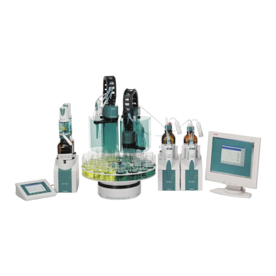
- Page 5 Fig. 1: The Titrando system ...................... 1 Fig. 2: Front view of a Titrando with internal dosing drive............5 Fig. 3: Front view of a Titrando for the use of external dosing devices ........6 Fig. 4: Rear view of the Titrando ....................7 Fig.
- Page 6 Contents Titrando Installation Instructions...
-
Page 7: Introduction
(700/800 Dosinos and 685/805 Dosimats), stirrers and titration stands, etc. Figure 1 shows you the flexibility of the Titrando system. On the left a Ti- trando is shown with external dosing devices operated by the Touch Control. To the right of it you can see an automation system consisting of a USB Sample Processor, a Titrando with internal dosing drive and a Dosimat operated by the PC Control software. -
Page 8: Instrument Description
1.1 Instrument description Additional information about the Titrando system can be found on the Internet under www.titrando.com. Information about specific applications can be found in our "Applica- tion Bulletins" and "Application Notes"; these can be obtained free of charge from your local Metrohm agency or downloaded from the Internet under www.metrohm.com. -
Page 9: Information About The Installation Instructions
Description of possible errors and how to remedy them Appendix Technical data, standard equipment, optional accessories, warranty and declaration of conformity Index In order to find the information you require about the Titrando you should either use the Table of contents or the Index. Titrando Installation Instructions... -
Page 10: Notation And Pictograms
Attention This symbol indicates important information that you should read before continuing. Information This symbol indicates additional information and tips that may be particularly useful. Titrando Installation Instructions... -
Page 11: Parts And Controls
1 Introduction 1.3 Parts and controls Fig. 2: Front view of a Titrando with internal dosing drive Guide openings Coupling for centering the exchange unit for switching the flat cock Push rod "On" LED of the dosing drive Lights up when the Titrando is con-... -
Page 12: Fig. 3: Front View Of A Titrando For The Use Of External Dosing Devices
1.3 Parts and controls Fig. 3: Front view of a Titrando for the use of external dosing devices Bottle holder "On" LED with holding clips, for two reagent bot- Lights up when the Titrando is con- tles nected to the mains supply and a con- troller (Touch Control or computer) is connected and switched on. -
Page 13: Fig. 4: Rear View Of The Titrando
1 Introduction Fig. 4: Rear view of the Titrando USB connections USB 1 and USB 2 Measuring interface 1 (Input 1) and USB ports (type A) for connection of Measuring interface 2 (Input 2) printer, keyboard, barcode reader, ad- Models 2.8XX.0010: 1 measuring inter-... -
Page 14: Safety Notes
Only qualified Metrohm technicians should carry out service work on electronic components. • Do not open the Titrando housing. This could destroy the Titrando. Inside the housing there are no components that the user can ser- vice or exchange. Electrical safety when handling the Titrando is guaranteed within the framework of the IEC 61010 Standard. -
Page 15: Installation
2 Installation This section describes what you should pay attention to when unpack- ing and setting up the Titrando. It also informs you about how a com- plete titration system – from a simple system with stirrer and printer up to a complicated system with additional dosing devices, sample changer and balance –... -
Page 16: Overview
More detailed information can be found in the given sections. Setup Section 2.2 Touch Control/Computer connection Section 2.3 Stirrer/Titration stand connection Section 2.4.1 Dosing device connection Section 2.4.2 and 2.4.3 Printer connection Section 2.5.1 Balance connection Section 2.5.2 Titrando Installation Instructions... -
Page 17: Instrument Setup
The Touch Control with contact-sensitive screen forms a “stand- alone” titrator together with the Titrando. • A computer can be used to control the Titrando by using the PC software PC Control or tiamo. Attention! Make sure that the mains cable has been removed from the power supply socket before setting up or breaking connections between the instruments. -
Page 18: Touch Control Connection
Control. After switch-on automatic system tests are carried out on both the Ti- trando and the Touch Control. The "On" LED on the Titrando lights up when the system test is finished and the instrument is ready for use. Attention! -
Page 19: Computer Connection
Connect all peripheral devices (see Section 2.4 and 2.5) before you connect the Titrando to the mains supply. Connect the Titrando to the mains supply. The LED "On" on the Ti- trando will not yet light up! Connect the Titrando to a USB connection (type A) on your com- puter with the 6.2151.000 cable (see the instruction manual for your... -
Page 20: Device Connection At The Msb
The Titrando will be recognized automatically. When the PC Control or tiamo software is started a system test will be carried out automatically on the Titrando. The LED "On" on the Titrando lights up when the sys- tem test is finished and the instrument is ready for use. -
Page 21: Connecting Stirrers And Titration Stands
The stand and the stand support are included with the stirrer or titration stand. Fasten the stand support to the base of the Titrando with the four screws supplied. Decide whether you want to attach the stirrer to the right or left of the Titrando. -
Page 22: Attaching The Exchange Unit To The Titrando
Fig. 10: Attaching the exchange unit to the Titrando Slide the exchange unit onto the Titrando so that it snaps into posi- tion and the "Status" LED slowly blinks. If the exchange unit has been properly positioned then the exchange unit guide bolts will operate a microswitch and trigger the exchange unit initialization. - Page 23 Dosing device operating status There is no exchange unit at- tached. constant illumination The Titrando is ready for dosing or titrating. The exchange unit has been attached correctly and recognized and is now in the change position, i. e. the ex- change unit can be removed.
-
Page 24: Connecting An External Dosing Device
700 Dosino can be connected to Titrandos with an internal dosing drive and four of them to Titrandos without internal dosing drive. MSB 1 is occupied by the built-in dosing drive on the Titrando with internal dosing drive. Connect the dosing drive as shown in Fig. 11 and Fig. 12. -
Page 25: Fig. 12: Example For Connecting A Dosing Device: Titrando - 805 Dosimat
The 685 Dosimat is connected to the Titrando with the 6.2134.030 ca- ble. 685 Dosimat and 700 Dosino types must be connected directly to the MSB socket of the Titrando (see Fig. 8: Overview of MSB connec- tions). If you want to connect a stirrer (see Section 2.4.1) and an exter-... -
Page 26: Connecting A Remote Box
Connecting a remote box Instruments that are controlled by remote lines or can transmit signals to the Titrando via remote lines can be connected to the Titrando via the 6.2148.010 Remote box. The pin occupancy of the remote socket is described in the Instructions for Use for PC Control / Touch Control. -
Page 27: Device Connection At The Usb
USB hub (see Section 2.5.7). Attention! If you are operating the Titrando with Touch Control then make sure that the Touch Control is switched off while you are setting up or breaking the connections between the instruments. If you are operat- ing the Titrando with the PC software, end the program before setting up or breaking USB connections. -
Page 28: Connecting A Balance
(COM) of the computer. This is normally 9-pin and marked with the symbol IOIOI. If you are operating the Titrando with the Touch Control then you need the 6.2148.020 USB-RS232 box to connect a balance. -
Page 29: Fig. 15: Titrando - Usb-Rs232 Box - Balance
(type B). Connect one of the RS interfaces of the USB-RS232 box with the RS232 interface of the balance (see Table for cables). Fig. 15: Titrando – USB-RS232 box – Balance Switch on the Touch Control. Switch on the balance. -
Page 30: Connecting A Usb Sample Processor / Robotic Titrosampler
Use the 6.2151.000 cable to connect the USB connection of the first Titrando / Dosing Interface (type A) with the controller socket of the second Titrando / Dosing Interface. Fig. 17: Titrando – Titrando/Dosing Interface Switch on the Touch Control or start the PC Control/tiamo software. -
Page 31: Connecting A Pc Keyboard (Titrando With Touch Control Only)
Connecting a PC keyboard (Titrando with Touch Control only) The PC keyboard is used as an aid for entering text and numbers. If you are operating the Titrando with the Touch Control then you can connect a PC keyboard with USB interface to the Titrando. Current keyboard models that can be connected are listed on the Internet under www.titrando.com. -
Page 32: Connecting A Usb Hub
Connecting a USB hub If you would like to connect more than two devices to the USB connec- tion of the Titrando then you can use an additional commercially avail- able USB hub (distributor). If you are operating the Titrando with the Touch Control then you should use a self-powered USB hub. - Page 33 2 Installation PC Control and tiamo If the Titrando system is operated with the PC Control/tiamo software, a Bluetooth USB adapter can be connected to a USB port of the com- puter (or of the Titrando/USB Sample Processor). The driver software (for MS Windows 2000/XP), supplied by the manufacturer of the Blue- tooth adapter, must be installed as specified in the related instructions.
- Page 34 The data transfer parameters of instrument and adapter must agree with each other. The Bluetooth se- rial adapter must be defined as Acceptor and not as Initiator of a serial connection. Authentication with a PIN code is not supported. Titrando Installation Instructions...
-
Page 35: Sensor Connection
857 Titrando depending on the Titrando's version. Connect the iConnect plug of the 854 iConnect to the socket "iCon- nect" of the 857 Titrando. Make sure that the mark on the plug points to the mark on the Titrando as shown in the figure. -
Page 36: Differential Potentiometry
When positioning the elec- trode and buret tip you must also take the stirring direction into ac- count. Fig. 20: Recommended arrangement of magnetic stirring bar (1), electrode (2) and buret tip (3) Titrando Installation Instructions... -
Page 37: Assembly Of The Karl Fischer Titration Cell
2 Installation 2.6.4 Assembly of the Karl Fischer titration cell Install the titration cell for volumetric KF titrations according to the fol- lowing figures: Fig. 21: Drawing of the KF titration cell 6.5609.000 Titrando Installation Instructions... -
Page 38: Update Of The Instrument Software
Position of the buret tip for KF re- agent 2.7 Update of the instrument software The Update of the instrument software is described in the Instructions for Use for PC Control / Touch Control or in the tiamo help. Titrando Installation Instructions... -
Page 39: Troubleshooting
Either the Touch Control or Check the plug connections and light up although the the computer is not switched switch on the Touch Control or the Titrando is con- on, or the plugs are not computer. nected to the mains plugged in correctly. - Page 40 3.1 Problems Problem Possible cause Measures Titrando with internal The dosing drive is over- Switch off the Touch Control or end dosing drive only: loaded because the flat cock PC Control/tiamo. Check whether "Status" LED blinks is blocked. the exchange unit can be removed.
-
Page 41: Appendix
Automatic temperature compensation, for NTC sensors R (25 °C) and B can be 25/50 configured. Polarizer 1 measuring input for polarized electrodes –125.0 ... +125.0 µA in 2.5 µA steps Polarization current Ipol Polarization potential Upol –1250 ... +1250 mV in 25 mV steps Titrando Installation Instructions... -
Page 42: Specification Of The Measuring Inputs
± 1 digit, without sensor error, under reference conditions potentiometric and voltametric amperometric for a NTC-Sensor with R (25 °C) = 30'000 Ohm and B (25/50) = 4100 K. Measuring cycle: 100 ms for all measuring ranges Titrando Installation Instructions... -
Page 43: Internal Dosing Device
Touch Control connection With built-in Touch Control cable Computer connection With 6.2151.000 cable MSB connections (MSB = Metrohm Serial Bus) Dosing device Connection of max. 3 external dosing devices of the type Dosimat or Dosino to Titrandos with internal dos-... -
Page 44: Safety Specifications
–20 °C ... +60 °C Transport –40 °C ... +60 °C 4.1.11 Reference conditions Ambient temperature +25 °C (±3 °C) Rel. humidity ≤ 60 % Warmed-up condition Instrument in operation for at least 30 min Validity of data After adjustment Titrando Installation Instructions... -
Page 45: Dimensions
4 Appendix 4.1.12 Dimensions Titrando with internal dosing drive Housing material Polybutylene terephthalate (PBT) Width 142 mm Height (without exch. unit) 164 mm Height (with exch. unit) approx. 450 mm Depth 239 mm Weight (without exch. unit) 2948 g Titrando without internal dosing drive... -
Page 46: Standard Equipment
4.2 Standard equipment 4.2 Standard equipment Immediately upon receipt of the Titrando please check that the delivery is complete. The illustrations in the accessory lists are not to the same scale. 4.2.1 808 Titrando The 808 Titrando is available in the 2 following versions: •... -
Page 47: 809 Titrando
4 Appendix 4.2.2 809 Titrando The 809 Titrando is available in the 2 following versions: • 2.809.0010 809 Titrando with one measuring interface • 2.809.0020 809 Titrando with two galvanically separated measuring interfaces The information given in brackets refers to 2.809.0020. -
Page 48: 835 Titrando
4.2 Standard equipment 4.2.3 835 Titrando The 835 Titrando is available in the 2 following versions: • 2.835.0010 835 Titrando with one measuring interface • 2.835.0020 835 Titrando with two galvanically separated measuring interfaces The information given in brackets refers to 2.835.0020. -
Page 49: 836 Titrando
4 Appendix 4.2.4 836 Titrando The 836 Titrando is available in the 2 following versions: • 2.836.0010 836 Titrando with one measuring interface • 2.836.0020 836 Titrando with two galvanically separated measuring interfaces The information given in brackets refers to 2.836.0020. -
Page 50: 841 Titrando
4.2 Standard equipment 4.2.5 841 Titrando The 841 Titrando is available in the following version: • 2.841.0010 841 Titrando with one measuring interface Order no. Description 1.841.0010 841 Titrando with one measuring interface 6.5609.000 Karl Fischer titration equipment (see Section 4.3.4 and Fig. 21) 6.2043.005... -
Page 51: 842 Titrando
4 Appendix 4.2.6 842 Titrando The 842 Titrando is available in the following version: • 2.842.0010 842 Titrando with one measuring interface Order no. Description 1.842.0010 842 Titrando with one measuring interface 6.0262.100 Ecotrode Plus Combined LL pH glass electrode with fixed ground-joint diaphragm 6.2104.020... -
Page 52: 857 Titrando
4.2 Standard equipment 4.2.7 857 Titrando The 857 Titrando is available in the 2 following versions: • 2.857.0010 857 Titrando with one measuring interface for 854 iConnect • 2.857.0020 857 Titrando with two galvanically separated measuring interfaces (one for 854 iConnect, one for 854 iConnect and conventional sensors) The information given in brackets refers to 2.857.0020. -
Page 53: Additional Instruments And Optional Accessories
2.801.0010 801 Magnetic stirrer without stand 2.804.0040 804 Titration stand for 802 Rod stirrer, with stand and electrode holder for mounting on Titrando 2.804.0010 804 Titration stand for 802 Rod stirrer, without stand 2.802.0040 802 Rod stirrer for 804 Titration stand 6.1909.010... -
Page 54: Karl Fischer Titration Equipment 6.5609.000
Drying tube with cover and O-ring 6.1414.030 KF titration vessel upper part 6.1415.220 Titration vessel 20 ... 90 mL 6.1415.250 Titration vessel 50 ... 150 mL 6.1448.010 Septum 6.1903.020 PTFE-stirring bar 16 mm 6.1903.030 PTFE-stirring bar 25 mm Titrando Installation Instructions... -
Page 55: Dosing Devices
6.3032.210 807 Dosing unit with 10 mL glass cylinder 6.3032.220 807 Dosing unit with 20 mL glass cylinder 6.3032.250 807 Dosing unit with 50 mL glass cylinder 6.2061.010 Bottle holder for Dosinos (Reagent Organizer) for 2 bottles Titrando Installation Instructions... -
Page 56: Combined Ph Electrodes
Combined Au ring electrode 4.3.8 Ion-sensitive electrodes and surfactant electrodes Order no. Description 6.0502.140 Ion-sensitive electrode for Cu 6.0502.150 Ion- sensitive electrode for F 6.0508.110 Ion- sensitive electrode for Ca 6.0507.010 NIO surfactant electrode for nonionic surfactants Titrando Installation Instructions... -
Page 57: Karl Fischer Electrodes
Ag/AgCl reference electrode filled with LiCl sat. in ethanol with ground diaphragm 6.0750.100 LL ISE Reference Ag/AgCl reference electrode with fixed ground-joint diaphragm, bridge elec- trolyte c(KCl) = 3 mol/L, length 133 mm, with Metrohm socket B 4.3.11 Temperature sensors Order no. Description 6.1110.100 Pt1000 resistance thermometer 6.2103.130... -
Page 58: Cables For Electrodes And Other Accessories
4.3.12 Cables for electrodes and other accessories Order no. Description 6.2104.020 Connection cable for Metrohm electrodes with plug head, length 1 m 6.2104.030 Connection cable for Metrohm electrodes with plug head, length 2 m 6.2104.140 Connection cable for resistance thermometer with 2 mm-plug, length 1 m 6.2104.150... -
Page 59: Cables For Balances
Cable for Sartorius balances 25 p./m – 9 p./f (2 m) 6.2134.120 Cable for Mettler AX/MX/UMX/PG and AB-S balances 9 p./f – 9 p./m (1.8 m) 6.2146.020 Cable for Mettler AT/AM/PM balances 25 p./m – Mettler plug (2 m) Titrando Installation Instructions... -
Page 60: Warranty And Conformity
Lack of an official damage report releases Metrohm from any liability to pay compensation. If any instruments and parts have to be returned then the original pack- aging should be used if at all possible. -
Page 61: Declaration Of Conformity For 808 Titrando
EN 61010-1 Safety requirements for electrical equipment for measurement, control and laboratory Metrohm Ltd. is holder of the SQS-certificate of the quality system ISO 9001 for quality assurance in design/development, production, installation and servicing. The system software, stored in Read Only Memories (ROMs) has been validated in connection with standard operating procedures in respect to functionality and performance. -
Page 62: Declaration Of Conformity For 809 Titrando
EN 61010-1 Safety requirements for electrical equipment for measurement, control and laboratory Metrohm Ltd. is holder of the SQS-certificate of the quality system ISO 9001 for quality assurance in design/development, production, installation and servicing. The system software, stored in Read Only Memories (ROMs) has been validated in connection with standard operating procedures in respect to functionality and performance. -
Page 63: Declaration Of Conformity For 835 Titrando
EN 61010-1 Safety requirements for electrical equipment for measurement, control and laboratory Metrohm Ltd. is holder of the SQS-certificate of the quality system ISO 9001 for quality assurance in design/development, production, installation and servicing. The system software, stored in Read Only Memories (ROMs) has been validated in connection with standard operating procedures in respect to functionality and performance. -
Page 64: Declaration Of Conformity For 836 Titrando
EN 61010-1 Safety requirements for electrical equipment for measurement, control and laboratory Metrohm Ltd. is holder of the SQS-certificate of the quality system ISO 9001 for quality assurance in design/development, production, installation and servicing. The system software, stored in Read Only Memories (ROMs) has been validated in connection with standard operating procedures in respect to functionality and performance. -
Page 65: Declaration Of Conformity For 841 Titrando
EN 61010-1 Safety requirements for electrical equipment for measurement, control and laboratory Metrohm Ltd. is holder of the SQS-certificate of the quality system ISO 9001 for quality assurance in design/development, production, installation and servicing. The system software, stored in Read Only Memories (ROMs) has been validated in connection with standard operating procedures in respect to functionality and performance. -
Page 66: Declaration Of Conformity For 842 Titrando
EN 61010-1 Safety requirements for electrical equipment for measurement, control and laboratory Metrohm Ltd. is holder of the SQS-certificate of the quality system ISO 9001 for quality assurance in design/development, production, installation and servicing. The system software, stored in Read Only Memories (ROMs) has been validated in connection with standard operating procedures in respect to functionality and performance. -
Page 67: Declaration Of Conformity For 857 Titrando
EN 61010-1 Safety requirements for electrical equipment for measurement, control and laboratory Metrohm Ltd. is holder of the SQS-certificate of the quality system ISO 9001 for quality assurance in design/development, production, installation and servicing. The system software, stored in Read Only Memories (ROMs) has been validated in connection with standard operating procedures in respect to functionality and performance. -
Page 68: Quality Management Principles
Metrohm Ltd. holds the ISO 9001 Certificate, registration number 10872-02, issued by SQS (Swiss Association for Quality and Management Systems). Internal and external au- dits are carried out periodically to assure that the standards defined by Metrohm’s QM Manual are maintained. -
Page 69: Index
5 Index 5 Index Dosing unit......19, 49 Metal electrodes .....50 Dosino.......37, 49 Metrohm Serial Bus ....37 Accessories ......47 MSB ........37 Ambient temperature ....38 Connection ....7, 14 Attaching the exchange unit ...16 Electrical safety......8 Electromagnetic compatibility 38 NTC........29, 35 EMC ........38 Balance ........22... - Page 70 Titration modes....... 35 USB-RS232 box....22, 52 Update Titration stand ....14, 47 Instrument software ..32 Connection ....15 USB......... 37 Warranty........54 Titration vessel......47 connection....... 7 Setup ......30 Connection ....21 Touch Control ......25 Titrando Installation Instructions...
Need help?
Do you have a question about the Titrando and is the answer not in the manual?
Questions and answers