
Related Manuals for Metrohm Inline Ultrafiltration 2


Summary of Contents for Metrohm Inline Ultrafiltration 2
- Page 1 IC equipment IC equipment: Inline Ultrafiltration 2 - push mode Manual 8.0108.8026EN/2020-05-22...
- Page 3 Metrohm AG CH-9100 Herisau Switzerland Phone +41 71 353 85 85 Fax +41 71 353 89 01 info@metrohm.com www.metrohm.com IC equipment IC equipment: Inline Ultrafiltration 2 - push mode 6.05330.110 Manual 8.0108.8026EN/2020-05-22...
- Page 4 Technical Communication Metrohm AG CH-9100 Herisau techcom@metrohm.com This documentation is protected by copyright. All rights reserved. This documentation has been prepared with great care. However, errors can never be entirely ruled out. Please send comments regarding possible errors to the address above.
-
Page 5: Table Of Contents
Mode of operation of the pull mode ......... 3 Sample volume ..............4 3 Overview Parts of the IC equipment: Inline Ultrafiltration 2 - push mode ..................5 Flow diagram of the IC equipment: Inline Ultrafiltration 2 - push mode ............... 7 Components of the ultrafiltration cell ........ - Page 6 Table of contents ■■■■■■■■■■■■■■■■■■■■■■ 8 Accessories Index ■■■■■■■■ IC equipment: Inline Ultrafiltration 2 - push mode...
- Page 7 ■■■■■■■■■■■■■■■■■■■■■■ Table of figures Table of figures Figure 1 IC equipment: Inline Ultrafiltration 2 - push mode – Parts ....5 Figure 2 Flow diagram of the IC equipment: Inline Ultrafiltration 2 - push mode ....................7 Figure 3 Ultrafiltration cell – Parts ..............8 Figure 4 Ultrafiltration cell –...
-
Page 9: Introduction
Inline Ultrafiltration directly before injec- tion. The main component of the IC equipment: Inline Ultrafiltration 2 - push mode is the ultrafiltration cell. This cell is suitable for the filtration of sam- ples with high requirements regarding filtration effectiveness and sample throughput. -
Page 10: Symbols And Conventions
WARNING This symbol draws attention to a possible biological hazard. CAUTION This symbol draws attention to possible damage to instruments or instrument parts. NOTE This symbol highlights additional information and tips. ■■■■■■■■ IC equipment: Inline Ultrafiltration 2 - push mode... -
Page 11: Mode Of Operation Of Ultrafiltration
Thus, the required sample volume is lower in the pull mode than in the push mode (see chapter 2.3, page 4). IC equipment: Inline Ultrafiltration 2 - push mode ■■■■■■■■... -
Page 12: Sample Volume
Due to the additional volume of the peristaltic pump tubings, the required volume is considerably higher in the push mode than in the pull mode. ■■■■■■■■ IC equipment: Inline Ultrafiltration 2 - push mode... -
Page 13: Overview
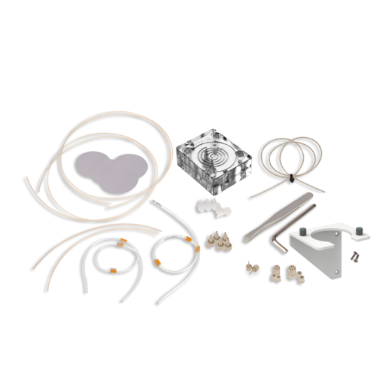
Parts of the IC equipment: Inline Ultrafiltration 2 - push mode Figure 1 IC equipment: Inline Ultrafiltration 2 - push mode – Parts Table 1 Parts of the IC equipment: Inline Ultrafiltration 2 - push mode Article number Article name Number 6.2714.020 Filtration membrane 1 6.1803.040... - Page 14 3.1 Parts of the IC equipment: Inline Ultrafiltration 2 - push mode ■■■■■■■■■■■■■■■■■■■■■■ Article number Article name Number 6.02057.030 Filtration cell holder 6.2744.160 Pump tubing connection with locking nut 6.2744.034 Coupling olive/UNF 10/32, 2x 6.2744.070 Pressure screw, short, 5x 6.2744.000 Pressure screw PVDF, 5x 6.1826.320...
-
Page 15: Flow Diagram Of The Ic Equipment: Inline Ultrafiltration 2 - Push Mode
3 Overview Flow diagram of the IC equipment: Inline Ultrafiltra- tion 2 - push mode Figure 2 Flow diagram of the IC equipment: Inline Ultrafiltration 2 - push mode 6.1831.160 6.1803.050 PEEK capillary, 0.5 mm ID / 70 cm PTFE capillary, 0.5 mm ID / 20 cm 6.1803.040... -
Page 16: Components Of The Ultrafiltration Cell
3.3 Components of the ultrafiltration cell ■■■■■■■■■■■■■■■■■■■■■■ Components of the ultrafiltration cell Figure 3 Ultrafiltration cell – Parts Stopper Sample chamber Filtrate chamber Screws for screwing together the sample chamber and the filtrate chamber ■■■■■■■■ IC equipment: Inline Ultrafiltration 2 - push mode... -
Page 17: Connectors Of The Ultrafiltration Cell
■■■■■■■■■■■■■■■■■■■■■■ 3 Overview Connectors of the ultrafiltration cell Figure 4 Ultrafiltration cell – Connectors Filtrate chamber Filtrate outlet labeled OUT Sample chamber Sample inlet labeled IN Sample outlet labeled OUT IC equipment: Inline Ultrafiltration 2 - push mode ■■■■■■■■... -
Page 18: Installation
Place the ultrafiltration cell on the table with the filtrate chamber ■ facing upwards. The screws face upwards. 2 Removing the screws Loosen the screws with the hex key. ■ The screws cannot be removed from the filtrate chamber. ■■■■■■■■ IC equipment: Inline Ultrafiltration 2 - push mode... - Page 19 (PMMA). Use ultrapure water or a water-ethanol mixture (70:30) for clean- ing the ultrafiltration cell. Rinse both chambers with ultrapure water. ■ Dry both chambers with a lint-free cloth. ■ IC equipment: Inline Ultrafiltration 2 - push mode ■■■■■■■■...
- Page 20 Place the filtration membrane in a petri dish filled with ultrapure ■ water and allow to hydrate for approx. 2 minutes. 6 Inserting the filtration membrane NOTICE The filtration membrane must not dry out before it is inserted! ■■■■■■■■ IC equipment: Inline Ultrafiltration 2 - push mode...
- Page 21 9 If the ultrafiltration cell is not used immediately, seal the sample inlet, the sample outlet and the filtrate outlet with the 3 green stoppers. This allows for the filtration membrane to stay moist. IC equipment: Inline Ultrafiltration 2 - push mode ■■■■■■■■...
-
Page 22: Connecting The Ultrafiltration Cell
NOTICE In order to keep dead volume to a minimum, the capillaries of the IC ■ equipment: Inline Ultrafiltration 2 - push mode are as short as possi- ble. To prevent the capillaries leading into the ion chromatograph from ■... - Page 23 (6.1826.390) using a pressure screw (6.2744.070). Tighten the PTFE capillary (6.1803.050) to the outlet of the pump ■ tubing with yellow stoppers (6.1826.390) using a pressure screw (6.2744.070). IC equipment: Inline Ultrafiltration 2 - push mode ■■■■■■■■...
- Page 24 6.1803.050 6.2744.000 6.2744.000 6.2744.000 6.1803.050 6.1803.040 Tighten the PTFE capillary (6.1803.050) to the inlet IN of the sam- ■ ple chamber using a PVDF pressure screw (6.2744.000). ■■■■■■■■ IC equipment: Inline Ultrafiltration 2 - push mode...
-
Page 25: Inserting The Ultrafiltration Cell
■ Ultrafiltration cell 2 (6.02729.110) ■ 1 Attaching the holder Tighten the filtration cell holder (6.02057.030) to the sample changer (see manual for the sample changer). 2 Inserting the ultrafiltration cell IC equipment: Inline Ultrafiltration 2 - push mode ■■■■■■■■... -
Page 26: Purging The Ultrafiltration Cell
If air bubbles are trapped in the cell, then unscrew the PTFE capil- ■ laries from the filtrate outlet and from the sample outlet and wait until the air bubbles have escaped. Afterwards, tighten the capilla- ries to the ultrafiltration cell again. ■■■■■■■■ IC equipment: Inline Ultrafiltration 2 - push mode... -
Page 27: Operation
0.5%, 5 µm 10 µm permeation 0.5%, 5 µm 12 µm no permeation 0.5%, 1.5 µm 0.15 µm no permeation 0.5%, 1.5 µm 3 µm permeation Nominal pore size according to manufacturer's statement. IC equipment: Inline Ultrafiltration 2 - push mode ■■■■■■■■... - Page 28 Due to the lower filter thickness, the retention capacity of filtration mem- branes may be lower than that of filters with the same pore size but a higher filter thickness. This must be taken into account when selecting an appropriate filtration membrane. ■■■■■■■■ IC equipment: Inline Ultrafiltration 2 - push mode...
-
Page 29: Maintenance
The table Service life of the filtration membrane contains samples that were filtered with the ultrafiltration cell and a filtration membrane 1 (6.2714.020) with a pore size of 0.2 µm and analyzed on a Metrohm ion chromatograph. The listed results were obtained with Inline Ultrafiltration (push mode). The results are to be seen as examples, not guidelines. -
Page 30: Replacing The Filtration Membrane
Take the ultrafiltration cell out of the holder. ■ 2 Cleaning the ultrafiltration cell Carry out the instruction steps 2 to 8 of the procedure Inserting the filtration membrane on page 10. ■■■■■■■■ IC equipment: Inline Ultrafiltration 2 - push mode... - Page 31 4 Inserting the ultrafiltration cell into the holder Place the ultrafiltration cell back in the holder (see chapter 4.3, page 17). 5 Purging the ultrafiltration cell Purge the ultrafiltration cell (see chapter 4.4, page 18). IC equipment: Inline Ultrafiltration 2 - push mode ■■■■■■■■...
-
Page 32: Technical Specifications
Water or water-ethanol mixture (70:30) bility (no other organic solvents) Cell volume Sample chamber: 240 µL Filtrate chamber: 120 µL Filtration membrane 1 (6.2714.020) Pore diameter 0.2 µm Membrane diame- 47 mm Material Regenerated cellulose ■■■■■■■■ IC equipment: Inline Ultrafiltration 2 - push mode... - Page 33 NOTICE Once you have received your new product, we recommend download- ing the accessories list from the Internet, printing it out and keeping it together with the manual for reference purposes. IC equipment: Inline Ultrafiltration 2 - push mode ■■■■■■■■...
- Page 34 Install Sample volume ..... 4, 19 Capillaries ......14 Select Installation ....... 10 Filtration membrane ... 19 Volume ........4 Mode of operation Technical specifications ..... 24 Pull mode ......3 ■■■■■■■■ IC equipment: Inline Ultrafiltration 2 - push mode...
Need help?
Do you have a question about the Inline Ultrafiltration 2 and is the answer not in the manual?
Questions and answers