Table of Contents
Advertisement
Advertisement
Chapters
Table of Contents

Subscribe to Our Youtube Channel
Related Manuals for Bruker BVT3000


Summary of Contents for Bruker BVT3000
- Page 1 Variable Temperature Unit Technical Manual BVT3000 Version BRUKER...
- Page 2 The information in this manual may be altered without notice. BRUKER accepts no responsibility for actions taken as a result of use of this manual. BRUKER accepts no liability for any mis- takes contained in the manual, leading to coincidental damage, whether during installation or operation of the instrument.
-
Page 3: Table Of Contents
Contents Contents ............... 3 Index ..............5 Description ............. 7 Introduction ................. 7 BVT3000 main components ..........8 Parts location ..............9 Principle of operation ............9 The front panel ..............10 Gas flow circuit ..............11 Setting up the gas flow ..........11 Front panel connectors ............ - Page 4 SV (Software version) ............ 47 WB (Write BBIS) ............48 WR (Write record) ............49 XR (Extract a record) ............. 50 Technical specifications........51 Specifications ..............51 Security fuses ..............52 Schematics ............53 Figures ..............63 Tables ..............65 4 (67) BRUKER BVT3000 Version 003...
-
Page 5: Index
................27 evaporator ......................17 exchanger ......................17 fuses........................52 Gas flow indicator....................10 LN2 evaporator ....................20 remote interface control ..................27 Sensor selection....................25 Temperature controller..................7 thermocouple ......................9 BVT3000 Version 003 BRUKER 5 (67) - Page 6 Index 6 (67) BRUKER BVT3000 Version 003...
-
Page 7: Description
Description Introduction The new variable temperature unit BVT3000 for precise sample temperature reg- ulation is equiped with a microcontroller interface for remote control by the host computer. The BVT3000 is manufactured in a separate housing. The unit includes: - A main board called interface board with a microcontroller. -
Page 8: Bvt3000 Main Components
BVT3000 main components The interface board has a microcontroller for remote control of the BVT3000. Two RS232 links are on this printed circuit. One link, on the front panel side, is for the communication with host computer and the other for communication with the Eu- rotherm 902 temperature controller. -
Page 9: Parts Location
Principle of operation The sample is heated by a constant gas flow delivered by the BVT3000. A tem- perature sensor (e.g. a thermocouple) located under the sample tube measures the gas temperature. The temperature controller compares the probe temperature to the target temperature programmed by the operator, and regulates the power applied to the heater in order to stabilise the gas temperature. -
Page 10: The Front Panel
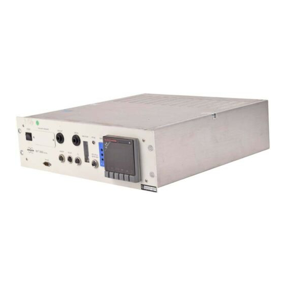
RS232 connector Heater connector BCU05 connector N2 connector Gas flow indicator BTO2000 power supply or BVTB 3500 Thermocouple connector type T Eurotherm controller Figure 1.3. BVT3000 front panel AUXILIARY SENSORS GAS OUT GAS IN EUROTHERM GAS FLOW SENSOR PT100 POWER... -
Page 11: Gas Flow Circuit
Connect the BVT3000 gas input to a dry air or N2 gas line. The input pressure should be at least 4 bar and must not exceed 8 bar. Power on the BVT3000. The default value of the flow rate is set according to the position of jumper JP6 to JP8. -
Page 12: Table 1.1. Flow Rate Versus Command
Flow rate versus command Decimal Combination Flow rate (l/h) combination ABCD 0000 0001 0010 0011 0100 0101 0110 0111 1000 1070 1001 1200 1010 1335 1011 1470 1100 1600 1101 1735 1110 1870 1111 2000 12 (67) BRUKER BVT3000 Version 003... -
Page 13: Front Panel Connectors
7 pins NMR 8 pins ESR heater + heater + heater + security thermocouple + heater - security thermocouple - security thermocouple + heater - security thermocouple - heater - heater + heater - BVT3000 Version 003 BRUKER 13 (67) -
Page 14: Pt100 Connector
Table 1.3. Pt100 connector pin assignment SIGNAL current + measure measure current - Note : This connector is also used to connect the BTO2000. Pin 2 and 3 are used as signal input pins. 14 (67) BRUKER BVT3000 Version 003... -
Page 15: Thermocouple Connector
Thermocouple connector 1.7.3 Figure 1.7. Thermocouple connector (Front view) CONST - Table 1.4. Thermocouple T pin assignment SIGNAL (Cu) Shield (Cu) Thermocouple + (Co.) Thermocouple - Other thermocouple connectors have the same pin assignement. BVT3000 Version 003 BRUKER 15 (67) -
Page 16: Rs232 Connector
Description RS232 connector 1.7.4 Figure 1.8. RS232 male connector (Front view) Table 1.5. RS232 connector pin assignment SIGNAL 16 (67) BRUKER BVT3000 Version 003... -
Page 17: N2 Connector (Option)
BCU05 connector 1.7.6 Figure 1.10. BCU05 connector Table 1.7. BCU05 connector pin assignment PIN NUMBER SIGNAL NAME COMMENT heater on turns on the BCU05 when high (>2,4v) dgnd digital ground not connected BVT3000 Version 003 BRUKER 17 (67) -
Page 18: Bvtb 3500 Connector
0 to 10 volt power control output pgnd power ground pgnd power ground thermocouple safety thermocouple input b_relay BVTB 3500 heater relay command b_connected if grounded BVTB 3500 is detected The BVTB3500 is a power booster for the BVT3000. 18 (67) BRUKER BVT3000 Version 003... -
Page 19: Options
Options Auxiliary sensors module - BASM The BVT3000 can be equipped with an electronic module for auxiliary tempera- ture measurement. This module can receive up to 4 sensors to acquire more temperature in spec- trometer environment (ambient temperature, extra temperature in special probe head for exemple). -
Page 20: Manual Command Module - Bmcm
Low temperature options For sample temperature regulation below room temperature one must use cold gas. The BVT3000 can be equipped with three optional cold gas production devic- • Liquid nitrogen exchanger. •... -
Page 21: Liquid Nitrogen Exchanger
This avoids sample freezing. Regulation accuracy is unchanged. Exchanger presentation 2.4.1 Figure 2.3. Exchanger principle BVT3x00 Transfer line N2 gas in Cold N2 out Valve block Isothermal tank Liquid nitrogen Refill level sensor Tube Empty level sensor BVT3000 Version 003 BRUKER 21 (67) -
Page 22: Liquid Nitrogen Evaporator
200 Watts (38V on a 7 ohm heater). The cold gas is transferred to the probe through a flexible transfer line. For this option, a printed circuit needs to be installed inside the BVT3000. This electronically controls the power applied to the liquid nitrogen heater and simulta- neously monitors the liquid nitrogen level in the tank. -
Page 23: Bcu05 Gas Cooler
- 40 °C. The BCU05 has a cable which must be connected to the BVT3000 on the connec- tor marked BCU05. When the heater is ON a signal is delivered to turn on the compressor of the BCU05. - Page 24 Options 24 (67) BRUKER BVT3000 Version 003...
-
Page 25: Configuration
Configuration Sensor selection The BVT3000 can be used with different types of sensors: • Thermocouple T or E for NMR, and K for ESR spectrometer • BTO2000 • PT100 sensor Warning: Never connect two types of sensors at a same time on the BVT3000. -
Page 26: Table 3.1. Eurotherm Sensor Code
. C2 will be displayed. 8. Now Press the selection button . ICONF appears. Press the scroll button until LEAVE appears. Press the left selection button again. Configuration is now complete and the temperature is displayed. 26 (67) BRUKER BVT3000 Version 003... -
Page 27: Remote Interface Control
Microcontroller interface This interface has several functions: • Host computer - EUROTHERM transparent communication through a serial port • Transmission of BVT3000 internal status to the host computer. • Probe heater on/off control • Gas flow control. • Installed option control: 1. -
Page 28: Commands And Communication Protocol
Eurotherm controller. If the command is processed by the Eurotherm, the an- swer is returned to the host computer via the interface. Control Characters Six non printing ASCII characters are used to control the messages that are ex- changed between host computer and BVT3000. Table 4.1. Control characters NAME... -
Page 29: List Of Commands
4 (for test only) reads interface version (software, hardware and installed options) reads BBIS memory content writes to a BBIS memory location writes a record to the BVT3000 transmit a hexadecimal record to the host BVT3000 Version 003 BRUKER... -
Page 30: Rs232 Link Characteristics
Remote interface control Rs232 link characteristics The serial link allows a host computer to communicate with the BVT3000. It is a three wire link with no hardware or software handshake. The communication pa- rameters are 9600 bauds, 1 start bit, even parity, 1 stop bit. The RS232 connector pin assignment and naming is explained above in "RS232 connector pin as-... -
Page 31: Table 4.3. Authorised Commands
Authorised functions Table 4.3. Authorised commands WITH WITH COMMANDS STANDARD PROBLEM EVAPORATOR EXCHANGER BVT3000 Version 003 BRUKER 31 (67) -
Page 32: Af (Air Flow)
STX AF > Value ETX BCC Description: This command allows gas flow delivery to be controlled. Rules: Value is a 4 characters string. Table "Flow rate versus com- mand" on page 12 shows the different gas flow deliveries. 32 (67) BRUKER BVT3000 Version 003... -
Page 33: Cm (Check Memory For Test Only)
EOT 0 0 0 0 CM ENQ Response: ACK if the RAM test has complete. NACK if the test failed. Description: CM starts a complete RAM test. WARNING: After the (ACK or NACK) answer the interface always RESET. BVT3000 Version 003 BRUKER 33 (67) -
Page 34: Co (Communications Speed)
A B C D E 1 9 2 0 0 _ 9 6 0 0 _ 4 8 0 0 _ 2 4 0 0 _ 1 2 0 0 NB: «_» represent the space character. 34 (67) BRUKER BVT3000 Version 003... -
Page 35: Dl (Download)
Description: Allows the user to get information about download. Rules:Val = '0': No download in progress. Val = '1': download in progress but flash eprom is not erased. Val = '2': download in progress and flash eprom is erased. BVT3000 Version 003 BRUKER 35 (67) -
Page 36: Dt (Dac Check For Test Only)
EOT 0 0 0 0 DT state ETX BCC Response: Description: DT starts a liquid nitrogen DAC test. Rules: state can be «0» or «1». 1 means test on. 0 means test off. 0 COMMANDS 36 (67) BRUKER BVT3000 Version 003... -
Page 37: Error Status)
BBIS available bbiscs1 BBIS checksum error block 1 bbiscs2 BBIS checksum error block 2 bbiscs3 BBIS checksum error block 3 bbiscs4 BBIS checksum error block 4 BVT3000 Version 003 BRUKER 37 (67) -
Page 38: Hp (Heater Power)
Description: This command allows to read the heater's state. Rules: State can be '0' or '1'. «1» means that heater is ON «0» means that heater is OFF NB: after power on the heater is OFF. 38 (67) BRUKER BVT3000 Version 003... -
Page 39: Is (Interface Status)
1 = LN2 tank is empty. evaporator status 1 = LN2 heater is on not used 1 always booster connected 1 = BVTB3500 present reserved 0 always reserved 0 always reserved 0 always reserved 0 always reserved 0 always BVT3000 Version 003 BRUKER 39 (67) -
Page 40: Nh (Nitrogen Heater)
Description: This command allows the liquid nitrogen heater power to be read back. Rules: Value from 0 to 100%, is a string up to 5 characters long. The string can begin with 1 to 5 spaces or «0». NB: Value is a DECIMAL code. 40 (67) BRUKER BVT3000 Version 003... -
Page 41: Np (Nitrogen Heater Power)
State can be «0» or «1». A equal «1» means that liquid nitrogen heater is ON A equal «0» means that liquid nitrogen heater is OFF NB: After power on the nitrogen heater power is at «0» BVT3000 Version 003 BRUKER 41 (67) -
Page 42: P1 (Port 1 For Test Only)
Remote interface control P1 (Port 1 for test only) 4.8.6 This port represents the main status of the BVT3000 unit. Port 1 is described in the following table Table 4.6. Port 1 definition NAME FUNCTION heater 1 = Probe heater is ON... -
Page 43: P2 (Port 2 For Test Only)
A and B are always «0». The third character represents the state of port 2 bits 4 to 7 while the fourth character represents the state of the bits 0 to 3. All the characters are hexadecimal. BVT3000 Version 003 BRUKER 43 (67) -
Page 44: P3 (Port 3 For Test Only)
Remote interface control P3 (Port 3 for test only) 4.8.8 Port 3 allows the internal status of the BVT3000 to be read. It is composed as follows: Table 4.8. Port3 definition NAME FUNCTION heater on 1 = probe heater is ON... -
Page 45: P4 (Port 4 For Test Only)
Authorised functions P4 (Port 4 for test only) 4.8.9 Port 4 allows the internal status of the BVT3000 to be read and allows the valves to be set at Power On. It is composed as follows: Table 4.9. Port 4 definition... -
Page 46: Rb (Read Bbis)
- 1: BVT3X00 motherboard address - 2: BVTB3500 (Booster) address - 3: Address unused - 4: Address unused - 5: Address unused - 6: Address unused - 7: Address unused All other values generates a NACK response 46 (67) BRUKER BVT3000 Version 003... -
Page 47: Software Version)
The different option identifications are defined as follows: '1' Thermocouple module option. ’2’: Liquid nitrogen Evaporator option. ’3’: Liquid nitrogen Evaporator option+ thermocouple module. ’4’: Liquid nitrogen Exchanger option. '5': Liquid nitrogen Exchanger option+ thermocouple module. '6': Problem detected. BVT3000 Version 003 BRUKER 47 (67) -
Page 48: Wb (Write Bbis)
- 1: BVT3X00 motherboard address - 2: BOOSTER address - 3: Address unused - 4: Address unused - 5: Address unused - 6: Address unused - 7: Address unused All other values generate a NACK response 48 (67) BRUKER BVT3000 Version 003... -
Page 49: Wr (Write Record)
Description: TR command allows records, extracted from a ".hex" file to be trans- fered to the BVT3X00. Rules: Rec value represents an intel-hex record. First character («:»- ASCII 3A), Cr an Lf are supressed BVT3000 Version 003 BRUKER 49 (67) -
Page 50: Xr (Extract A Record)
"XR0" request to terminate the upload process and returns to normal mode. If BVT3X00 receives an «XR3» command, the previous record is sent again. An «XR0» Command must be sent to terminate the upload sequence and return to normal mode. 50 (67) BRUKER BVT3000 Version 003... -
Page 51: Technical Specifications
4 bars mini, 8 bars maxi (dry air or N gas). Gas flow rate : • 200 l/h to 2000 l/h with 15 steps Options For regulation at low temperature following devices can be used: • BCU05 • exchanger BVT3000 Version 003 BRUKER 51 (67) -
Page 52: Security Fuses
200 W heater. Security fuses Some important electronic functions are fuse protected. To replace a blown fuse, turn off the BVT3000 and disconnect the main power cord. A faulty fuse must always be replaced with the same type. Table 5.1. -
Page 53: Schematics
Schematics BVT3000 Version 003 BRUKER 53 (67) - Page 54 from MAIN SUPPLY to Eurotherm to sheet 2 220Vac SYNCHRO THYRISTOR SYNC to LN2 option to Transfo TP22 7815CT +15P TP28 41761-03 41761-03 41761-03 41761-03 1000uF 10uF TVS315 +/-15V FOR ANALOG PARTS 0.5AT PGND 1 2 3 1 2 3 1 2 3 1 2 3 MAINS1...
- Page 55 +15P BOOSTER CONNECTOR PGND +15P -15P from sheet 1 +5V CPU CPUVCC U54D RESERVED FOR SLAVE from sheet 6 GND_BTO GND BTO 22.1k +15_BTO +15V BTO HEATER THERMOCOUPLE RESERVED FOR -15V from sheet 1 CPUGND GND CPU LM324 U47B I2C BUS POWER CONTROL OUTPUT (0 TO 10V) 100R PGND...
- Page 56 U38A +15P LN2_EMPTY- LN2_EMPTY U37C PGND U37A U37B 0 = Valve open 4001 EXCH_CONN- EXCHANGER VALVE -15P HEATER_RLY VALVE_EXCH- from sheet 6 to sheet 7 4025 4025 4025 301K TP21 MUX_TC +15P U54B from sheet 2 301K JP11 OVERHEAT U54A +15P to sheet 7 4.99k...
- Page 57 FROM UART DATA BUS D[0..7] D[0..7] INTR- D[0..7] sheet 5 to sheet 5,6,7 CHARGE PUMP 18pF BOOT 4.7k EA/VP P0.0 11.059M P0.1 220n P0.2 P0.3 FLASH_VPON- P0.4 P0.5 SHDN PGMODE 220n P0.6 18pF P0.7 FLASH RESET P2.0 P2.1 INTR- CS_FLASH- P3.2/INT0 P2.2 VOUT...
- Page 58 from sheet 1 CPUVCC RS232 I/O CPUGND OPTION 1: DGND - BOTH PORTS USED - DC/DC CONVERTER NOT MOUNTED - VCC/GND AND +5V/GNDX SHORTED TOGETHER ISOLATED +5V - NO ISOLATION TO RS232 DRIVER OPTION 2: - ONLY HOST PORT IN USE - UART NOT MOUNTED - VCC/GND AND +5V/GNDX ISOLATED INTERRUPT REQUEST...
- Page 59 to sheet 3 EVAP_CTRL- HEATER & LN2 POWER ENABLE POWER_EN- HEATER_CTRL- from sheet 3 to sheet 2,4 +24V +15P BBIS EEPROM 4.75k SWITCH BOOSTER_CONN- I2C CONNECTOR FRONT-PANEL LED + from sheet 2 HEATER SWITCH LED - 4.75k CN MKK02 D 1.5K RS8A/10K 22.1k...
- Page 60 from sheet 1 PLP1 EVAPORATOR HEATER STATUS CPU SIDE +15P PLP0 I_EVAP_STAT +15P CPUVCC PLP3 TO PORT 4 PLP2 I_VALVE PGND CPUGND PLP5 DGND PLP4 BCU05 CONNECTOR -15P PLP7 PLP6 +24V +24V RS8A/2K7 +15P VREF 100R 74LS32 2K74 U32A CN MKK03 D U41A +15P LM358...
- Page 62 Schematics 62 (67) BRUKER BVT3000 Version 003...
-
Page 63: Figures
1 Description Figure 1.1. BVT3000 block diagram ............8 Figure 1.2. Parts location ................9 Figure 1.3. BVT3000 front panel ............10 Figure 1.4. Gas flow circuit ..............11 Figure 1.5. Heater connector (Front view) ..........13 Figure 1.6. Pt100 connector (Front view) ..........14 Figure 1.7. - Page 64 Figures 64 (67) BRUKER BVT3000 Version 003...
-
Page 65: Tables
Port 1 definition ............. 42 Table 4.7. Port2 definition .............. 43 Table 4.8. Port3 definition .............. 44 Table 4.9. Port 4 definition ............. 45 Table 4.10. Record format ..............49 5 Technical specifications 6 Schematics BVT3000 Version 003 BRUKER 65 (67) - Page 66 Tables 66 (67) BRUKER BVT3000 Version 003...
- Page 67 Lastpage BVT3000 Version 003 BRUKER 67 (67)
Need help?
Do you have a question about the BVT3000 and is the answer not in the manual?
Questions and answers