
Related Manuals for Bruker minispec


Summary of Contents for Bruker minispec
- Page 1 ● Sample Automation XYZ Sample Changer User Manual Version 003 Innovation with Integrity...
- Page 2 © October 07, 2016 Bruker Corporation Document Number: 10000031930 P/N: H148850 For further technical assistance for this product, please do not hesitate to contact your nearest BRUKER dealer or contact us directly at: Bruker Corporation Am Silberstreifen 76287 Rheinstetten Germany Phone: + 49 721 5161 0 E-mail: minispec.SLS@bruker.com...
-
Page 3: Table Of Contents
Contents Contents About This Manual .......................... 7 Policy Statement ......................... 7 Symbols and Conventions .................... 7 Introduction............................ 9 Overview .......................... 9 2.1.1 Who Should Read This Book.................... 9 Intended Use........................ 9 Where to Go for More Information .................. 9 Safety.............................. 11 Safety Notices........................ 11 3.1.1 Power Cord Set Requirements .................. 11 3.1.2 Power Cord Safety Maintenance .................. 11 3.1.3... - Page 4 Contents 6.9.1 Aligning the Sample Changer ................... 32 6.9.2 Testing the Gripper ...................... 32 Safety Barrier Assembly Installation (Optional) ................ 33 Preparing the Sample Changer .................. 33 Safety Barrier Assembly .................... 36 Operation............................ 43 Establishing Optimal Operating Conditions .............. 43 8.1.1 Purchasing Supplies ...................... 44 Starting the Sample Changer.................... 44 Stopping Sample Changer Movement ................ 45 Shutting Down the Sample Changer................. 45 Using the Safety Barrier.................... 45...
- Page 5 Contents 14.2.1 Power Requirements ...................... 70 14.2.2 Data Connectors - Sample Changer................. 71 14.2.3 Data Connectors – Temperature Units ................ 71 14.3 Pneumatic connections..................... 71 15 Contact .............................. 73 List of Figures........................... 75 List of Tables ............................ 77 Index .............................. 79 H148850_3_003...
- Page 6 Contents H148850_3_003...
-
Page 7: About This Manual
Options and accessories may or may not be illustrated in each figure. Policy Statement It is Bruker’s policy to improve products as new techniques and components become available. Bruker reserves the right to change specifications at any time. - Page 8 About This Manual WARNING WARNING indicates a hazardous situation, which, if not avoided, could result in death or serious injury. This is the consequence of not following the warning. 1. This is the safety condition. u This is the safety instruction. CAUTION CAUTION indicates a hazardous situation, which, if not avoided, may result in minor or moderate injury or severe material or property damage.
-
Page 9: Introduction
The Sample Automation XYZ sample changer is designed for use as a temperature- controlled, pick-and-place automation system in analytical laboratories performing chemical analysis of samples. Where to Go for More Information For additional information on this and other products refer to the Bruker website: www.bruker.com. H148850_3_003... - Page 10 Introduction H148850_3_003...
-
Page 11: Safety
Any retrofitting, repairs or dismantling of the device must only be carried out by Bruker Service or personnel authorized by Bruker. Damage due to servicing that is not authorized by Bruker is not covered by your warranty. 3.1.1 Power Cord Set Requirements The power cord set supplied with the device meets the requirements of the country where the device was purchased. -
Page 12: Operating Environment
Safety WARNING Fire and Shock Hazard Incorrect installation or use of the power supply may result in a fire or shock hazard. u Use only the provided power supply. u The power supply must be plugged into an outlet which has a protective ground connection. -
Page 13: Mechanical Hazards
Safety WARNING Chemical Hazards Incorrect use of chemicals used in and near the device may result in injury or property damage. u Learn about the chemicals which will be used in and near the device, and observe the necessary precautions. u Always use appropriate personal protective equipment, including protective eyewear. -
Page 14: Explanation Of Caution And Warning Notices
Safety WARNING Pinch Hazard Keep fingers, hair, and loose clothing away from the moving parts of the device. WARNING Laceration/Pinch/Puncture Hazard When the device power is left on, motors may move unexpectedly and cause injury. u Ensure the device power is off before proceeding with installation. 3.1.6 Explanation of Caution and Warning Notices Explanation of Caution and Warning Notices... -
Page 15: Explanation Of Regulatory Marks
Safety MODIFICATIONS The FCC requires the user to be notified that any changes or modifications made to this device that are not expressly approved by the manufacturer may void the user's authority to operate the equipment. CABLES Connections to this device must be made with shielded cables with metallic RFI/EMI connector hoods to maintain compliance with FCC Rules and Regulations. - Page 16 Safety H148850_3_003...
-
Page 17: Design And Function
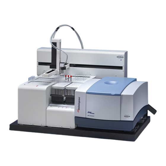
Design and Function Design and Function Sample Changer Components The following components are located on the front of the sample changer and are shipped with the sample changer. Figure 4.1: Sample Automation XYZ Sample Changer—Front View with TC3 (10 mm SFC Version), TC6 and MFC Analyzer 1 Arm: The arm moves the gripper horizontally 2 Z-Drive Assembly: The Z-Drive assembly moves the gripper vertically. -
Page 18: Figure 4.2: Sample Automation Xyz Sample Changer-Front View With Tc3 (2 Zone 26 Mm Version) And Sample Stage
Design and Function 9 Temperature Units: The temperature units each have several temperature zones which heat or cool the samples. Figure 4.2: Sample Automation XYZ Sample Changer—Front View with TC3 (2 Zone 26 mm Version) and Sample Stage 1 Arm: The arm moves the gripper horizontally. 2 Z-Drive Assembly: The Z-Drive assembly moves the gripper vertically. -
Page 19: Additional Equipment Required
Design and Function The following components are located on the back of the sample changer and are shipped with the sample changer: Figure 4.3: Sample Automation XYZ Sample Changer—Back View of Sample Changer Head. 1 Auxiliary I/O Port: Provides control signals to the gripper. 2 Power Switch: This switch turns the power to the sample changer on and off. -
Page 20: Optional Accessories
Design and Function • Temperature Units. The sample changer is typically used with two temperature units (sold separately): – TC3 Temperature Unit: One, two, or three discrete zones hold samples at a fixed temperature. – TC6 Temperature Unit: Each of the six zones can hold 10 samples at a user-defined temperature. -
Page 21: Transport, Packaging And Storage
Transport, Packaging and Storage Transport, Packaging and Storage WARNING Lifting Hazard Lifting without assistance may cause injury. u Two people are required to lift the device. u Lifting should be done with a person situated on either side of the device. u Never attempt to lift or move the device when the temperature units and NMR instrument are installed. - Page 22 Transport, Packaging and Storage H148850_3_003...
-
Page 23: Installation
Installation Installation Installation consists of the following steps: 1. Attach the Z-drive and assemble the sample changer. 2. Attach the enclosure back, if purchased. 3. Place the sample changer in its final position. 4. Mount the temperature units. 5. Mount the NMR instrument. 6. -
Page 24: Space Requirements
Installation 6.1.1.1 Space Requirements The recommended footprint for the Sample Automation XYZ sample changer (with or without optional enclosure) is shown in the following table. Recommended Space Including Cables/Tubing Height 1 m (23.0") Width 113 cm (41.0") Depth 1 m (31.0") Table 6.1: Physical Characteristics Allow at least 10 cm behind the device for cable egress, ventilation, and access to the power switches. -
Page 25: Installing The Temperature Units
Installation Installing the Temperature Units Each temperature unit comes with a manual which explains how to mount it on the sample changer and how to connect the cables. Mounting the NMR Instrument • Place the sample changer in its final operating position. Once the NMR instrument is mounted, the sample changer will be too heavy to move without a mechanical lift. -
Page 26: Without The Safety Barrier
Installation 6.4.1 Without the Safety Barrier • Decide whether to mount the button on the left or right side of the instrument. • Use the two included screws to attach the bracket to the side of the base. Figure 6.2: E-Stop Shown on Left Side of the Base •... -
Page 27: With The Safety Barrier
Installation • Install the two nuts on the mounting screws. Figure 6.5: Rear View of E-Stop After Mounting (shown mounted to safety barrier so that screw locations are more visible) • Replace the front of the button enclosure. • Connect the button to the back of the sample changer. Figure 6.6: E-stop Connected to the Sample Changer 6.4.2 With the Safety Barrier... -
Page 28: Connecting The Sample Changer To The Power Supply
Installation Connecting the Sample Changer to the Power Supply • Turn the sample changer power switch OFF. • Check the plug on the power cord to verify that it is of the correct type for your country. • Plug the power cord into a power outlet. •... -
Page 29: Figure 6.7: Message Showing That A Driver Was Not Found
Installation • If a driver is not found, click Back and install the drivers from the supplied installation media. Figure 6.7: Message Showing that a Driver was not Found. • Insert the installation media, if necessary. • Select Install from a specific location and click Next. Figure 6.8: Choosing to Install USB Driver •... -
Page 30: Figure 6.10: Searching For The Driver
Installation • Wait while the computer searches the media. Figure 6.10: Searching for the Driver • When the driver is found, select it and click Next. Figure 6.11: Selecting the Driver • The driver installation is complete. Figure 6.12: Driver Installation is Complete H148850_3_003... -
Page 31: Establishing An Rs-232 Serial Communications Interface
25 pin D- subminiature plug or receptacle) must be used, use the mating connector from the universal port adapter kit. You can order the adapter kit from Bruker or purchase an adapter locally to convert the serial port to a DB9M. Do not use a “null modem” adapter. -
Page 32: Aligning The Sample Changer
Installation 6.9.1 Aligning the Sample Changer Note: Before alignment, ensure that you have installed all sample changer components correctly. Also, ensure that you have securely tightened all thumbscrews and connected the communications cable from the host computer to the sample changer. You will need the following items: •... -
Page 33: Safety Barrier Assembly Installation (Optional)
Safety Barrier Assembly Installation (Optional) Safety Barrier Assembly Installation (Optional) This chapter describes how to install the optional ASX-7600 NMR safety barrier assembly. To assemble the ASX-7600HR NMR safety barrier you will need the following tools: • #1 Phillips screwdriver •... - Page 34 Safety Barrier Assembly Installation (Optional) Step 3: Remove the E-stop cover by unscrewing the four screws that hold the cover on. Step 4: Remove the E-stop bracket from back of the E-stop by removing the two screws with a 9/64” Allen wrench while holding the acorn nuts on the back. Step 5: Unplug the E-stop from the back of the autosampler.
- Page 35 Safety Barrier Assembly Installation (Optional) Step 6: Affix the four mounting brackets to the autosampler’s base using 10-32x.75 FHPH screws, Bag G, two on each side. Make sure the recessed holes for the two screws are facing out. Step 7: Remove the four screws holding the back panel of the instrument. Step 8: Install the mounting bracket on the left side of the autosampler as viewed from the front using the two screws that were removed previously.
- Page 36 Safety Barrier Assembly Installation (Optional) Safety Barrier Assembly When positioning the acrylic walls begin with the back segment. Step 1: While one person holds the acrylic wall steady, secure with two 6-32x0.625 PHPH, Bag A, screws. Ensure that the cables and tubing connected fit in the opening of the back panel and do not get pinched during assembly.
- Page 37 Safety Barrier Assembly Installation (Optional) Step 2: Fasten the braces to the back wall using 8-32x.375 PHPH, Bag B, screws, three on each bracket. Step 3: Next, identify the right wall. H148850_3_003...
- Page 38 Safety Barrier Assembly Installation (Optional) Step 4: One person should steady the acrylic wall while the second puts one 8-32x.1.5 PHPH, Bag E, screw in each of the base mounting brackets. Once tightened down, the wall will be secure enough to finish screwing in the remaining 8-32x.1.5 PHPH, Bag E, screws without the aid of the second person.
- Page 39 Safety Barrier Assembly Installation (Optional) Step 6: Unscrew the four screws joining the yellow cap to the button base and remove the cap. Step 7: Find the mounting holes on the outer side of the acrylic wall. H148850_3_003...
- Page 40 Safety Barrier Assembly Installation (Optional) Step 8: Use the two 8-32x.625 SHCS and 8-32 acorn nuts (bag C) to mount the stop to the wall. The bolts insert into the button’s base and the acorn nuts on the bottom of the wall. Use a 9/64”...
- Page 41 Safety Barrier Assembly Installation (Optional) Step 10: Secure the cap by replacing the four screws removed in step 6. Step 11: Mount the wall to the base of the autosampler, using the same procedure as described in step 4. Step 12: Join the wall to the top brace using 8-32x.375 PHPH, Bag B, screws, three per bracket.
- Page 42 Safety Barrier Assembly Installation (Optional) Step 15: The front door panel is next. This step needs two people. One to steady the panel, while the second secures one side with three 10 32x0.375 (Bag F) screws. Ensure that the key lock is on the top. When finished with one side move to the next while person two is still holding the panel steady.
-
Page 43: Operation
Operation Operation Before using the sample changer, ensure that your laboratory environment provides operating conditions that will prolong the life of the sample changer. Once the proper operating conditions are met, you can load samples and start the sample changer sequence run. -
Page 44: Purchasing Supplies
Operation 8.1.1 Purchasing Supplies Because the life-span of the sample vials varies, you should maintain an adequate supply of spare vials. When you need to purchase additional supplies, it is extremely important that you choose the appropriate sizes and materials. When you purchase sample vials, make sure they meet the following requirements: •... -
Page 45: Stopping Sample Changer Movement
Operation Stopping Sample Changer Movement In the event of an emergency: • Press the red E-stop button to stop sample changer movement. Figure 8.1: E-Stop Button To release the E-stop button, twist it clockwise. Shutting Down the Sample Changer To shut down the sample changer, complete the following steps: •... -
Page 46: Opening The Safety Barrier
Operation 8.5.1 Opening the Safety Barrier • Turn off the sample changer and unplug the power cord. • Use the key to turn the latch [2]. • Slide the handle toward the center [3]. Figure 8.2: Safety Barrier Latch To close the safety barrier •... -
Page 47: Sample Stage
The sample stage provides a platform to hold samples in a consistent, known position for a BRUKER Sample Automation XYZ sample changer, as well as a space for an accessory such as a balance. The sample stage contains two removable racks allowing users to prepare sample vials away from the system. -
Page 48: Installing The Sample Stage
Sample Stage Installing the Sample Stage Follow the guidelines in the section Choosing a Location [} 23] to choose a location for the system. Keep in mind that: • You will need to be able to access the back of the system to install cables. •... -
Page 49: Figure 9.2: Opening On The Bottom Of The Sample Stage
Sample Stage • Carefully place the sample stage on its side. The bottom of the sample stage contains a cutout allowing access to the address dial. Figure 9.2: Opening on the Bottom of the Sample Stage. • Insert a wooden probe through the cut out and rotate the dial to “C” or 12. Figure 9.3: Address Dial. -
Page 50: Figure 9.4: Dual Sample Stage Addresses-26 Mm
Sample Stage The sample stages are now configured for dual operations. The 11 and 12 values will be used as the RS-485 address of the sample stage for all sample stage commands. Figure 9.4: Dual Sample Stage Addresses—26 mm. Figure 9.5: Dual Sample Stage Addresses—10 mm. H148850_3_003... -
Page 51: Installing The Sample Stage On The Base
Sample Stage 9.1.3 Installing the Sample Stage on the Base WARNING Laceration/Pinch/Puncture Hazard When the device power is left on, motors may move unexpectedly and cause injury. u Ensure the device power is off before proceeding with installation. Figure 9.6: Base of the Sample Changer •... -
Page 52: Connecting The Data Cables
Sample Stage 9.1.4 Connecting the Data Cables The sample stage does not contain any active components. It simply receives commands at the serial port and relays them through the RX485 port. • Connect the 9-pin serial cable to the COM 2 port on the autosampler or to the host PC. Figure 9.7: Serial Connector on the Sample Stage •... -
Page 53: Operating The Sample Stage
Sample Stage WARNING Fire and Shock Hazard Incorrect installation or use of the power supply may result in a fire or shock hazard. u Use only the provided power supply. u The power supply must be plugged into an outlet which has a protective ground connection. - Page 54 Sample Stage H148850_3_003...
-
Page 55: 10 Maintenance
Maintenance 10 Maintenance Routine maintenance of the sample changer consists of daily and weekly cleaning of specific sample changer components. Routine maintenance also includes checking for leaks or other damage. CAUTION Static Discharge Buildup Hazard Static discharge buildup may cause a short‑circuit or other material damage. u Discharge static buildup and ground the device cabinet before performing any maintenance. -
Page 56: Weekly Cleaning
Maintenance NOTICE Cleaning Agent Hazard Cleaning agent coming into contact with the lead screws may result in material damage. u Do not allow the cleaning agent to come into contact with the lead screws. • Repeat step two, using a towel dampened with clear water. This process removes any remaining contaminants. -
Page 57: Mounting The Z-Drive Assembly
Maintenance Procedure: • Use a clean cloth to remove surface dust. • Dampen a new cloth with the cleaning solution. • Wipe the enclosure. • Dry by gently buffing with a new cloth. Avoid scratching the cover while drying. The autosampler and enclosure must be thoroughly dry before you turn the power on. -
Page 58: Figure 10.2: Sliding The Z-Drive Onto The Y-Arm
Maintenance • Slide the Z-drive onto the y-arm. Figure 10.2: Sliding the Z-Drive onto the Y-Arm. • Secure the screw. Figure 10.3: Attaching the Z-Drive to the Carriage. H148850_3_003... -
Page 59: Figure 10.4: Attaching The Z-Drive Strain Relief Block
Maintenance • Screw the strain-relief block to the sample changer. Figure 10.4: Attaching the Z-Drive Strain Relief Block • Plug the cable into the 15-pin connection port on the rear of the sample changer, and tighten the screws. Figure 10.5: Connecting the Z-Drive Cable H148850_3_003... -
Page 60: Using Tubing Tamers
Maintenance 10.3.2 Using Tubing Tamers • Attach the Tubing Tamer to the Z-Drive. Run any communications wires and sample tubing along the Z-Drive cable through the tamers. Figure 10.6: Connecting Tubing Tamer Figure 10.7: Tubing Tamer Properly Installed on Z-Drive Cable H148850_3_003... -
Page 61: Connecting The Pneumatic Tubing
Maintenance 10.3.3 Connecting the Pneumatic Tubing • Connect the tubing to the appropriate fittings on the back of the sample changer. Figure 10.8: Gripper Tubing Connection on Back of Sample Changer • Connect the tubing to the appropriate fittings on the gripper. Figure 10.9: Gripper Tubing Connected to the Gripper on the Z-Drive H148850_3_003... -
Page 62: Connecting The Auxiliary Connector
Maintenance 10.3.4 Connecting the Auxiliary Connector • Connect the wires from the gripper to the auxiliary connector as shown. Figure 10.10: Auxiliary Connector • Route the tubes and wires through the tubing tamers. Make sure that the tubes and wires are positioned so that they will not catch on anything when the sample changer moves. Figure 10.11: Tubing After Installation H148850_3_003... -
Page 63: 11 Troubleshooting
NMR instrument, or the sample changer. This chapter explains how to troubleshoot sample changer problems. If you cannot solve a problem using the steps given in this chapter, you should contact BRUKER. 11.1 Power System Problems A possible cause of system malfunction is a problem in the power system. -
Page 64: Communications Interface Problems
Troubleshooting 11.2 Communications Interface Problems Operation of the sample changer is directed by the host computer. A malfunction can indicate a problem with the USB cable or with the configuration of the software on the host computer. The following sections explain how to troubleshoot these problems. 11.2.1 USB Cable Problems •... -
Page 65: 12 Replacement Of Parts
12.1 Returning the Unit for Repair If the Bruker Hotline diagnoses an instrument failure that requires a part to be returned for repair, please follow the procedure listed here: 1. Contact your local Bruker office to start the repair process (see Contact). Repair is always handled by your local Bruker office. - Page 66 Replacement of Parts H148850_3_003...
-
Page 67: 13 Dismantling And Disposal
Following the end of its operational life, the device must be dismantled and disposed of in accordance with the environmental regulations. Any retrofitting, repairs or dismantling of the device must only be carried out by Bruker Service or personnel authorized by Bruker. -
Page 68: Disposal Usa And Other Countries
Only 100% pre-decontaminated equipment can and will be accepted by Bruker BioSpin. A release document for decontamination can be inquired from your nearest Bruker BioSpin contact site, also to be used when repairs, going back to Bruker sites, are requested. In compliance with WEEE II directive: 2012/19/EU 13.3... -
Page 69: 14 Technical Data
Technical Data 14 Technical Data 14.1 Environmental Characteristics These environmental characteristics indicate the conditions for safe operation. Instrument performance may depend on the ambient conditions. Operating Temperature +5° C to +40° C (+41° F to +104° F) Non-Operating +0° C to +55° C (+32° to +131° F) Temperature Operating Altitude Up to 2,000 m (6,562 ft.) -
Page 70: Electrical Characteristics
Technical Data 14.2 Electrical Characteristics 14.2.1 Power Requirements Power Supply Input: AC Voltage, Frequency, and Current 100-240 V ~ 47-63 Hz 1.07 A Installation Category: CAT II (Line voltage in appliance and to wall outlet) Output: 24 V DC, 3.33 A Sample Changer Input: DC Voltage and Current... -
Page 71: Data Connectors - Sample Changer
Technical Data 14.2.2 Data Connectors - Sample Changer Note that the USB and COM connectors on the sample changer cannot be used at the same time. COM 1 DB-9 RS-232 serial connection to a controller PC (max ±12V DC, 8 mA). COM 2 DB-9 RS-232 serial connection to accessories or instruments (max ±12V DC, 8 mA). - Page 72 Technical Data H148850_3_003...
-
Page 73: 15 Contact
WEEE DE43181702 Bruker BioSpin Hotlines Contact our Bruker BioSpin service centers. Bruker BioSpin provides dedicated hotlines and service centers, so that our specialists can respond as quickly as possible to all your service requests, applications questions, software or technical needs. - Page 74 Contact H148850_3_003...
-
Page 75: List Of Figures
List of Figures List of Figures Figure 3.1: Overview of the Mechanical Hazards (Without Optional Safety Barrier) ...... Figure 3.2: Overview of the Mechanical Hazards (With Optional Safety Barrier) ......Figure 3.3: E-Stop Button ....................... Figure 4.1: Sample Automation XYZ Sample Changer—Front View with TC3 (10 mm SFC Ver- sion), TC6 and MFC Analyzer .................. - Page 76 List of Figures Figure 10.8: Gripper Tubing Connection on Back of Sample Changer..........Figure 10.9: Gripper Tubing Connected to the Gripper on the Z-Drive..........Figure 10.10: Auxiliary Connector....................... Figure 10.11: Tubing After Installation ....................H148850_3_003...
- Page 77 List of Tables List of Tables Table 6.1: Physical Characteristics..................... Table 14.1: Environmental Characteristics ................... Table 14.2: Power Requirements ......................Table 14.3: Data Connectors on the Sample Changer ................. Table 14.4: Data Connectors - Temperature Units ................H148850_3_003...
- Page 78 List of Tables H148850_3_003...
-
Page 79: Index
Index mains disconnect.......... 11 Index operator qualifications ........ 9 avis Canadien........... 15 pollution degree .......... 69 power connections .......... 28 Balance adapter kit........... 20 power-on procedure ........ 44 requirements ......... 24, 70 Power connections Sample Stage.......... 52 power cord............ 11 cleaning ............ 55 Condensation .......... 21, 48 qualifications, operator ........ 9 dimensions ............ 24 regulatory notices .......... 11 earthing ............ 24 electrical characteristics ........ 70... - Page 80 Index H148850_3_003...
- Page 81 H148850_3_003...
- Page 82 ● Bruker Corporation info@bruker.com www.bruker.com Order No: H148850...
Need help?
Do you have a question about the minispec and is the answer not in the manual?
Questions and answers