
Related Manuals for Carrier XCT7 40VCW117FQEE


Summary of Contents for Carrier XCT7 40VCW117FQEE
- Page 1 Wire controller Installation and Owner’s Manual MODEL NAME 40VCW117FQEE Edition: 2020-05...
- Page 2 MODEL CONFORMANCE TO EUROPEAN REGULATIONS: DISPOSAL REQUIREMENTS: All the products conform to the following European provision: Your air conditioning product is marked with this - Machinery Directive symbol. This means that electrical and electronic - Electromagnetic Compatibility products should not be mixed with unsorted household waste.
- Page 3 MODELLKONFORMANZ ENTSPRECHEND EUROPÄISCHEN VORSCHRIFTEN: ENTSORGUNGSANFORDERUNGEN: Alle Produkte entsprechen den folgenden europäischen Bestimmungen: Ihr Klimaprodukt ist mit diesem Symbol - Maschinenrichtlinie gekennzeichnet. Dies bedeutet, dass elektrische - Elektromagnetische Verträglichkeit und elektronische Produkte nicht mit unsortiertem Hausmüll gemischt werden dürfen. Versuchen Sie nicht, das System selbst zu zerlegen: Die ROHS Demontage der Klimaanlage und die Behandlung Les produits sont conformes aux exigences de la directive 2011/65/UE...
- Page 4 Contains fluorinated greenhouse gases covered by the Kyoto Protocol IMPORTANT INFORMATION REGARDING THE REFRIGERANT USED The filled-out label must be affixed close to the product This product contains fluorinated greenhouse gases covered by the Kyoto Protocol. Do not vent into the atmosphere. charging port (e.g., inside of the stop valve cover).
- Page 5 WICHTIGE INFORMATIONEN ZU DEM VERWENDETEN KÄLTEMITTEL Dieses Produkt enthält fluorierte Treibhausgase, die unter Das ausgefüllte Etikett muss in der Nähe des Produkts angebracht das Kyoto-Protokoll fallen. Nicht in die Atmosphäre entlüften. werden Ladeanschluss (z. B. innerhalb des Absperrventildeckels). Kühlmittel ty R410A GWP*-Wert: 2088 A enthält fluorierte Treibhausgase die unter das Kyoto Protokoll f *GWP = globales Erwärmungspotential...
-
Page 6: Table Of Contents
User Manual TABLE OF CONTENTS Parts and Functions Interface Display................1 Icons................... 2 Dip Switch.................. 4 Operation Mode Key..................6 Fan Key..................6 Temperature Adjustment Keys ........... 7 Special Function Special Function Selection ............8 Installer Settings Adjust ECO Parameters ............10 Child Lock ................ -
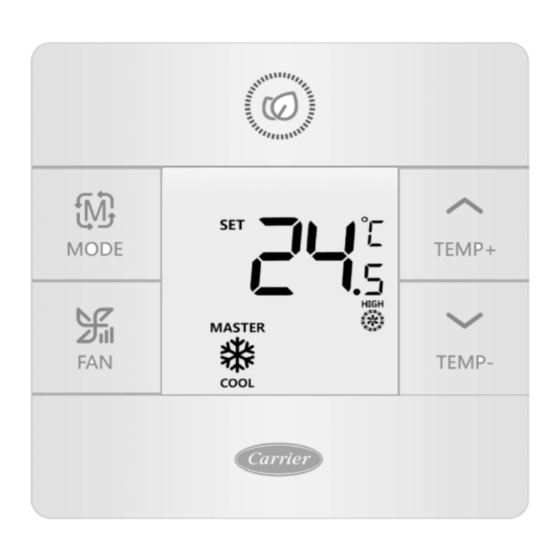
Page 7: Parts And Functions
Parts and Functions Interface Display Full display... - Page 8 Parts and Functions Room temperature display (dip switch SWl-2 on). Set temperature display Filter HRV (Heat Reclaim Ventilation), if HRV function is set, it will display this icon Error icon displays detected fault ECO mode on Central/lock when connected to a central controller UP/DOWN louver swing LEFT/RIGHT louver swing Child lock on...
-
Page 9: Dip Switch
Dip Switch Dip switch definition Dip Switch SWl\ Default Slave wired controller Master wired controller Swl-2 Room temperature display on Room temperature display off Swl-3 Room temperature collected from indoor unit Room temperature collected from controller Swl-4 System remains off after power loss Auto restart after power loss Swl-5 Old protocol (models develioed before Ayg, 2013... -
Page 10: Mode Key
Mode Key / Fan Key Mode key: Each press of the MODE button will change the operating mode from Auto - Cool - Heat- Fan - Dry {Dehumidification) –Auto. • Each mode has its initial default fan speed. Mode Fan speed Initial State Auto Auto... -
Page 11: Temperature Adjustment Keys
Temperature Temperature Adjustment Keys: Press the TEMP+ or TEMP- keys to change the temperature by 0.5 °C increments. • The temperature set point range for Auto, Cooling, Heating and Dry (Dehumidification) is 16°C to 30°C (If ECO is on, then temperature range will change as per the ECO setting parameters). •... -
Page 12: Special Function Selection
Function Selection Special Function Selection: With the control powered on, press and hold the TEMP+ for 5 seconds to enter the special function menu. All the spe- cial function icons will display. Use the TEMP+ and TEMP- buttons to move between icons. Use FAN button to select function... - Page 13 Function Selection Horizontal (up/down) louver setting. Press fan to enter. Use TEMP buttons to select louver position. Press fan to save. Vertical (left/right) louver setting. Press fan to enter. Use TEMP buttons to select louver position. Press fan to save. Clean Filter Alert.
-
Page 14: Installer Settings
Installer Setting Adjust ECO Parameters: (ICON) • Cooling: Power on the unit. Adjust set temperature to 30°C. Press and hold FAN and TEMP+ for 5 seconds. The minimum allowable set temperature will be displayed in the top right corner. Use TEMP+/- to change the parame- ter, then press FAN save. -
Page 15: Lock Settings
Lock Settings/ Fahrenheit Setting Central/Lock Function • Function is active only when system has a central control, such as the YCZ-A004. This setting is activated only by the central Control. Central Control On/Off function only available. Central Lock No functions available. Fahrenheit Setting and Display: •... -
Page 16: Temperature Compensation
Temperature Compensation Set Temperature Compensation: • With the display off, press and hold the FAN button for 5 seconds. The display will then show O (default) or current compensation setting. Use TEMP+/- buttons to adjust the compensation. Compensation can be set in 1 ° incre- ments +/- 8°F (0.5°C increments up to +/-4°C). -
Page 17: Error Checks
Error Checks How to check error: • lf there is an error, will display. • Check error: Press and hold TEMP- button for 5 seconds. The error history will appear in the top right corner. The current error will appear in the middle of the screen. lf there is no error, “--” will display. Mode Restriction Mode Restriction Function: •... -
Page 18: Wiring Instruction
Wiring Controller Wiring Instruction A: One Controller for up to 16 indoor TYPE 1, FOR4MXD6512G1000AA 4MXD6518G1000AA 4MXD6524G1000AA Indoor 1 Indoor 2 Indoor N Indoor 15 Indoor 16 Wire controller Wire controller Wire controller Wire controller Wire controller Control wiring of wire controller, polar. - Page 19 Wiring Controller Wiring Instruction Communication wiring Communication wiring length (m/ft) Dimensions of Wiring < 100m/328ft 0.3mm2x3-core shielded wire (22AWG, 3 wire) ≥100m/328ft and <200m/656ft 0.5mm2x3-core shielded wire (20AWG, 3 wire) ≥200m/656ft and <300m/984ft 0.75mm2x3-core shielded wire (18AWG, 3 wire) *Ground only one end of the shielded cable Wiring Diagrams yellow white...
- Page 20 Wiring Controller Wiring Instruction Communication wiring To take the front panel and back panel apart, slide the front panel up and press down on the back panel. Secure the back panel to the wall using screws. Connect the control wires. Attach the control to the back panel by aligning the bottom tabs and then pressing the top edge.
- Page 21 Information according to Directive 2006/42/EC (Name of the manufacture) Carrier SCS (Address, city, country) Route de Thil - 01120 Montluel – France...
- Page 22 The manufacturer reserves the right to change any product specifications without notice.
- Page 23 Controller cablato Installazione e manuale dell’utente NOME MODELLO 40VCW117FQEE Edizione: 2020-05...
- Page 24 Manuale dell’utente SOMMARIO Parti e funzioni Display interfaccia............... 1 Icone................... 2 Dip Switch.................. 4 Funzionamento Tasto Mode................Tasto Fan..................6 Tasti per la regolazione della temperatura........Funzione speciale Selezione della funzione speciale..........8 Impostazioni per l’installatore Regolazione dei parametri ECO..........10 Blocco bambini.................
-
Page 25: Parti E Funzioni
Parti e funzioni Display interfaccia Full display... - Page 26 Parti e funzioni Tasto Visualizzazione temperatura della stanza (dip switch SWl-2 acceso). Imposta visualizzazione della temperatura Filtro HRV (Heat Reclaim Ventilation), Se la funzione HRV è impostata, verrà mostrata questa icona L’icona di errore mostra il guasto rilevato Modalità ECO attiva Centrale/blocco quando collegato al controller centrale Oscillazione feritoia SU/GIÙ...
-
Page 27: Dip Switch
Dip Switch Definizione di dip switch Dip Switch SWl\ Predefi- nito Controller cablato Slave Controller cablato Master Swl-2 Visualizzazione della temperatura della stanza ON Visualizzazione della temperatura della stanza OFF Swl-3 Temperatura della stanza raccolta dall’unità interna Temperatura della stanza raccolta dal controller Swl-4 Il sistema resta spento dopo una perdita di tensione Riavvio automatico dopo una perdita di... -
Page 28: Tasto Mode
Tasto Mode/ Tasto Fan Tasto Mode: Ogni pressione del pulsante MODE cambierà la modalità di funzionamento da Auto - Freddo - Caldo - Ventola - Secco (Deumidificazione) - Auto. • Ciascuna modalità ha la sua velocità della ventola predefinita. Modalità Velocità... -
Page 29: Tasti Per La Regolazione Della Temperatura
Temperatura Tasti per la regolazione della temperatura: Premere i tasti TEMP+ o TEMP- per cambiare la temperatura con incrementi di 0,5 °C. • L’intervallo di temperatura impostato per Auto, Raffreddamento, Riscaldamento e Secco (Deumidificazione) va da 16°C a 30°C (se ECO è attiva, l’intervallo seguirà i parametri di ECO). •... -
Page 30: Selezione Della Funzione Speciale
Selezione della funzione Selezione della funzione speciale: Con il dispositivo di controllo acceso, tenere premuto il tasto TEMP+ per 5 secondi per entrare nel menù dedicato alla funzione speciale. Verranno mostrate tutte le icone delle funzioni speciali. Usare i pulsanti TEMP+ e TEMP- per spostarsi tra le icone. -
Page 31: Impostazioni Per L'installatore
Selezione della funzione Impostazione feritoia orizzontale (su/giù). Premere su fan per entrare. Usare i pulsanti TEMP per selezionare la posizione della feritoia. Premere su fan per salvare. Impostazione feritoia verticale (sinistra/destra). Premere su fan per entrare. Usare i pulsanti TEMP per selezionare la posizione della feritoia. Premere su fan per salvare. Avviso filtro pulito. -
Page 32: Regolazione Dei Parametri Eco
Impostazioni blocco/Impostazioni Fahrenheit Regolazione dei parametri ECO: (ICONA) • Raffreddamento: Accendere l’unità. Portare la temperatura a 30 °C. Tenere premuto FAN e TEMP+ per 5 secon- di. La temperatura minima consentita sarà mostrata nell’angolo in alto a destra. Usare TEMP+/- per modificare il parametro, poi premere FAN per salvare. - Page 33 Impostazioni blocco/Impostazioni Fahrenheit Funzione centrale/blocco • Funzione attiva solo quando il sistema dispone di un dispositivo di controllo centrale, come ad esempio il YCZ-A004. Questa impostazione può essere attivata solamente da dispositivo di controllo centrale. Dispositivo di controllo centrale Disponibile solo la funzione On/ Off.
-
Page 34: Compensazione Della Temperatura
Compensazione della temperatura Impostare la compensazione della temperatura: • Con il display spento, tenere premuto il tasto FAN per 5 secondi. Il display mostrerà O (default) oppure l’attuale impostazione di compensazione. Usare i +/- pulsanti TEMP per regolare la compensazione. La compensazione può... -
Page 35: Controllo Degli Errori
Controllo degli errori Come controllare gli errori: • Se viene rilevato un errore, verrà visualizzato • Controlla errore: Tenere premuto TEMP- per 5 secondi. La cronologia degli errori comparirà nell’angolo in alto a destra. L’errore attuale apparirà al centro dello schermo. Se non ci sono errori, comparirà “--”. Restrizione modalità... -
Page 36: Istruzioni Di Cablaggio
Istruzioni di cablaggio del controller cablato A: Un controller per un massimo di 16 unità interne TIPO 1, FOR4MXD6512G1000AA 4MXD6518G1000AA 4MXD6524G1000AA Unità interna 15 Unità interna 1 Unità interna 2 Unità interna N Unità interna 16 Controller cablato Controller cablato Controller cablato Controller cablato Controller cablato... - Page 37 Istruzioni di cablaggio del controller cablato Cablaggio di comunicazione Lunghezza cavo di comunicazione (m/piedi) Dimensioni del cavo < 100 m/328 piedi 0.3mm2x3-cavo schermato con anima (22AWG, 3 cavi) ≥100 m/328 piedi e <200 m/656 piedi 0,5 mm 2x3-cavo schermato con anima (20AWG, 3 cavi) ≥200 m/656 piedi e <300 m/984 piedi 0, 75 mm2x3-cavo schermato con anima (18AWG, 3 cavi) *Mettere a terra solo una estremità...
- Page 38 Istruzioni di cablaggio del controller cablato Cablaggio di comunicazione Per separare il pannello anteriore e il pannello posteriore, far scorrere il pannello anteriore verso l'alto e premere verso il basso sul pannello posteriore. Fissare il pannello posteriore alla parete utilizzando le viti. Collegare i cavi del dispositivo di controllo.
- Page 39 Informazioni in osservanza della Direttiva 2006/42/CE (Nome del produttore) Carrier SCS (Indirizzo, città, Paese) Route de Thil - 01120 Montluel – Francia...
- Page 40 Il produttore si riserva il diritto di modificare qualsiasi specifica del prodotto senza preavviso.
- Page 41 Contrôleur filaire Manuel d’installation et d’utilisation NOM DU MODÈLE 40VCW117FQEE Édition :2020-05...
- Page 42 Guide d’utilisation TABLE DES MATIÈRES Pièces et fonctions Affichage de l’interface..............1 Icônes..................2 Commutateur DIP................4 Fonctionnement Touche mode................6 Touche du ventilateur..............6 Touches de réglage de la température ........7 Fonction spéciale Sélection de la fonction spéciale ..........8 Réglages de l’installateur Ajuster les paramètres ECO .............10 Verrouillage enfant ..............10 Réglages de verrouillage ............11 Fahrenheit / Celsius ..............11...
-
Page 43: Pièces Et Fonctions
Pièces et fonctions Affichage de l’interface Full display... - Page 44 Pièces et fonctions Clé Affichage de la température ambiante (commutateur DIP SWl-2 activé). Affichage de la température de consigne Filtre HRV (Heat Reclaim Ventilation), si la fonction HRV est définie, cette icône s’affichera L’icône d’erreur affiche la défaillance détectée Mode ECO activé Central/verrouillage lorsqu’il est connecté...
-
Page 45: Commutateur Dip
Commutateur DIP Définition du commutateur DIP Commutateur DIP SWl\ Défaut Contrôleur filaire esclave Contrôleur filaire principal Swl-2 Affichage de la température ambiante activé Affichage de la température ambiante désactivé Swl-3 Température ambiante collectée à partir de l'unité Température ambiante collectée à partir intérieure du contrôleur Swl-4... -
Page 46: Touche Mode
Touche de mode / Touche de ventilateur Touche de mode : Chaque pression sur le bouton MODE changera le mode de fonctionnement à partir de Auto - Cool - Heat- Fan - Dry {Dehumidification) –Auto. • Chaque mode a sa vitesse initiale de ventilateur par défaut. Mode Vitesse du ventilateur État initial... -
Page 47: Touches De Réglage De La Température
Température Touches de réglage de la température : Appuyez sur les touches TEMP+ ou TEMP- pour modifier la température par incréments de 0,5 °C. • La plage de point de consigne de température pour Auto, Cooling, Heating et Dry (Dehumidification) est de 16 °C à... -
Page 48: Sélection De La Fonction Spéciale
Sélection de la fonction Sélection de la fonction spéciale Avec le contrôleur sous tension, maintenez la touche TEMP + enfoncée pendant 5 secondes pour accéder au menu des fonctions spéciales.Toutes les icônes de fonctions spéciales s’afficheront.Utilisez les boutons TEMP+ et TEMP- pour vous déplacer d’une icône à... - Page 49 Sélection de la fonction Réglage du volet horizontal (haut/bas).Appuyez sur Fan pour entrer.Utilisez les boutons TEMP pour sélectionner la position du volet.Appuyez sur Fan pour enregistrer Réglage du volet vertical (gauche/droite).Appuyez sur Fan pour entrer.Utilisez les boutons TEMP pour sélectionner la position du volet.Appuyez sur Fan pour enregistrer Alerte de nettoyage du filtre.Appuyez sur Fan pour réinitialiser.
-
Page 50: Réglages De L'installateur
Réglage de l’installateur Ajustez les paramètres ECO : (ICÔNE) • Refroidissement :Allumez l’appareil.Réglez la température de consigne sur 30 °C. Appuyez et maintenez FAN et TEMP+ pendant 5 secondes.La température de consigne minimale autorisée sera affichée dans le coin supérieur droit.Utilisez TEMP+/- pour changer le paramètre, puis appuyez sur FAN pour enregistrer.La température mini- male par défaut est de 23 °C. -
Page 51: Réglages De Verrouillage
Réglages de verrouillage/Réglage Fahrenheit Fonction centrale/de verrouillage • La fonction est active uniquement lorsque le système dispose d’un contrôle central, tel que le YCZ-A004.Ce ré- glage n’est activé que par le contrôleur central. Contrôleur central Fonction On/Off uniquement disponible. Verrouillage central Aucune fonction disponible. -
Page 52: Compensation De Température
Compensation de température Réglage de la Compensation de température : • Une fois l’affichage éteint, appuyez sur le bouton FAN et maintenez-le pendant 5 secondes.L’affichage montrera alors O (par défaut) ou le réglage de compensation actuel.Utilisez les boutons TEMP+/- pour régler la compensa- tion.La compensation peut être réglée par incréments de 1°... -
Page 53: Vérification Des Erreurs
Vérification des erreurs Comment vérifier l’erreur : • S’il y a une erreur, s’affichera. • Vérifiez l’erreur :Appuyez sur le button TEMP- et maintenez pendant 5 secondes.L’historique des erreurs apparaî- tra dans le coin supérieur droit.L’erreur actuelle apparaîtra au milieu de l’écran. S’il n’y a pas d’erreur, « - » s’affi- chera. -
Page 54: Instructions De Câblage
Instructions de câblage du contrôleur filaire A :Un contrôleur pour jusqu’à 16 unités intérieures TYPE 1, POUR 4MXD6512G1000AA 4MXD6518G1000AA 4MXD6524G1000AA Intérieure 15 Intérieure 2 Intérieure N Intérieure 16 Intérieure 1 Contrôleur filaire Contrôleur filaire Contrôleur filaire Contrôleur filaire Contrôleur filaire Câblage de contrôle du fil contrôleur, polaire. - Page 55 Instructions de câblage du contrôleur filaire Câblage de communication Longueur du câblage de communication (m/pi) Dimensions du câblage < 100 m/328 pieds Fil blindé de 0,3 mm 2x3 conducteurs (22 AWG, 3 fils) ≥ 100 m/328 pieds et < 200 m/656 pieds Fil blindé...
- Page 56 Instructions de câblage du contrôleur filaire Câblage de communication Pour séparer le panneau avant et le panneau arrière, faites glisser le panneau avant vers le haut et appuyez sur le pan- neau arrière. Fixez le panneau arrière au mur à l'aide des vis. Connectez les fils du contrôleur.
- Page 57 Informations selon la directive 2006/42/CE (Nom du fabricant) Carrier SCS (Adresse, ville, pays) Route de Thil - 01120 Montluel - France...
- Page 58 Le fabricant se réserve le droit de modifier les spécifications du produit sans préavis.
- Page 59 Kabelsteuerung Installations- und Bedienungsanleitung MODELLNAME 40VCW117FQEE Auflage: 2020-05...
- Page 60 Benutzerhandbuch INHALTSVERZEICHNIS Teile und Funktionen Schnittstellenanzeige ............1 Symbole ................2 DIP Schalter..............4 Operation Modus-Taste..............6 Ventilatorschlüssel ..........………6 Temperaturanpassungstasten ..........7 Spezialfunktion Sonderfunktionsauswahl ..........8 Installation-Einstellungen ECO-Parameter anpassen ..........10 Kindersicherung .............. 10 Sperreinstellungen ............11 Fahrenheit Celsius ..........
-
Page 61: Teile Und Funktionen
Teile und Funktionen Schnittstellenanzeige Full display... - Page 62 Teile und Funktionen Schlüssel Raumtemperaturanzeige (DIP-Schalter SWl-2 eingeschaltet). Temperaturanzeige einstellen Filter HRV (Wärmerückgewinnungslüftung): Wenn die HRV-Funktion eingestellt ist, wird dieses Symbol angezeigt Das Fehlersymbol zeigt den erkannten Fehler an ECO-Modus ein Zentral/Schloss bei Anschluss an eine zentrale Steuerung Auf/Ab-Jalousieschwingung LINKS/RECHTS Jalousieschwingung Kindersicherung an Master / Slave Master / Slave-Kabelsteuerung...
-
Page 63: Dip Schalter
DIP Schalter Definition des Dip-Schalters Dip-Schalter SWl\ AUSZUSCHALTEN Standard Slave-Kabelsteuerung Master-Kabelsteuerung AUSZUSCHAL- Swl-2 Raumtemperaturanzeige ein Raumtemperaturanzeige aus AUSZUSCHAL- Swl-3 Raumtemperatur vom Innengerät erfasst Raumtemperatur vom Regler AUSZUSCHAL- erfasst Swl-4 Das System bleibt nach einem Stromausfall aus- Automatischer Neustart nach AUSZUSCHAL- geschaltet Stromausfall Swl-5... -
Page 64: Modus-Taste
Modustaste / Ventilatortaste Modusschlüssel: Mit jedem Drücken der MODUS-Taste wird die Betriebsart von Auto - Cool - Heat - Fan - Dry (Entfeuchtung) - Auto geändert. • Jeder Modus hat seine anfängliche Standardventilatorgeschwindigkeit. Modus Ventilatorgeschwin- digkeit Ausgangszu- Auto Auto 24°C. stand Kühl Hoch... -
Page 65: Temperaturanpassungstasten
Temperatur Temperaturanpassungstasten: Drücken Sie die TEMP+ oder TEMP- Tasten, um die Temperatur in Schritten von 0,5°C zu ändern. • Der Temperatursollwertbereich für Auto, Kühlen, Heizen und Trocknen (Entfeuchten) beträgt 16°C bis 30°C (Wenn ECO eingeschaltet ist, ändert sich der Temperaturbereich gemäß den ECO-Einstellparametern). •... - Page 66 Funktionsauswahl Auswahl spezieller Funktionen: Halten Sie bei eingeschalteter Steuerung TEMP + 5 Sekunden lang gedrückt, um das Sonderfunktionsmenü aufzu- rufen. Alle Sonderfunktionssymbole werden angezeigt. Verwenden Sie die Tasten TEMP + und TEMP-, um zwischen den Symbolen zu wechseln. Verwenden Sie die VENTILATOR-Taste, um die Funktion auszuwählen...
- Page 67 Funktionsauswahl Horizontale Lamelleneinstellung (nach oben / unten). Verwenden Sie die Ventilator-Taste zum Bestätigen Verwenden Sie die TEMP-Tasten, um die Position der Luftklappe auszuwählen. Drücken Sie zum Speichern auf Ventilator. Vertikale (links / rechts) Luftklappeneinstellung. Verwenden Sie die Ventilator-Taste zum Bestätigen Verwenden Sie die TEMP-Tasten, um die Position der Luftklappe auszuwählen. Drücken Sie zum Speichern auf Ventilator.
-
Page 68: Installation-Einstellungen
Installation-Einstellung ECO-Parameter anpassen: (ICON) • Kühlung: Schalten Sie das Gerät ein. Stellen Sie die eingestellte Temperatur auf 30°C ein. Halten Sie FAN und TEMP + 5 Sekunden lang gedrückt. Die minimal zulässige eingestellte Temperatur wird in der oberen rechten Ecke angezeigt. Verwenden Sie TEMP +/-, um den Parameter zu ändern, und drücken Sie dann FAN um zu spei- chern. - Page 69 Einstellungen sperren/Fahrenheit einstellen Zentral- / Sperrfunktion • Die Funktion ist nur aktiv, wenn das System über eine zentrale Steuerung verfügt, z.B. den YCZ-A004. Diese Ein- stellung wird nur von der zentralen Steuerung aktiviert. Zentrale Steuerung Ein/Aus-Funktion nur verfügbar. Zentralverriegelung Keine Funktionen verfügbar. Fahrenheit Einstellung und Anzeige: •...
-
Page 70: Temperaturkompensation
Temperaturkompensation Temperaturkompensation einstellen: • Halten Sie bei ausgeschaltetem Display die FAN-Taste 5 Sekunden lang gedrückt. Das Display zeigt dann die Ein- stellung O (Standard) oder die aktuelle Kompensation an. Verwenden Sie die TEMP +/- Tasten, um die Kompen- sation anzupassen. Die Kompensation kann in Schritten von 1 ° +/- 8 ° F (0,5 ° C-Schritte bis +/- 4 ° C) eingestellt werden. -
Page 71: Fehlerprüfungen
Fehlerprüfungen So überprüfen Sie Fehler: • Wenn ein Fehler auftritt, wird angezeigt. • Fehler überprüfen: Halten Sie die TEMP-Taste 5 Sekunden lang gedrückt. Die Fehlergescichte wird in der oberen rechten Ecke angezeigt. Der aktuelle Fehler wird in der Mitte des Bildschirms angezeigt. Wenn kein Fehler vor- liegt, wird „-“... -
Page 72: Verdrahtungsanweisung
Verdrahtungsanweisung für Verdrah- tungssteuerung EIN: Ein Controller für bis zu 16 Innenräume TYP 1, FOR4MXD6512G1000AA 4MXD6518G1000AA 4MXD6524G1000AA Innen 15 Innen 2 Innen N Innen 16 Innen 1 Kabelsteuerung Kabelsteuerung Kabelsteuerung Kabelsteuerung Kabelsteuerung Verdrahtung des Kabels steuern Regler, polar. Kabelsteuerung TYP 2 FÜR 4MXD6536G1000AA 4MXD6548G1000AA 4MXD6560G1000AA Innen 16 (Haupt- Innen 1 Innen 2... - Page 73 Verdrahtungsanweisung für Verdrah- tungssteuerung Kommunikationsverkabelung Länge der Kommunikationsverkabelung (m/ft) Abmessungen der Verkabelung <100 m/328ft Abgeschirmter Draht mit 0,3 mm2 x 3 Adern (22 AWG, 3 Drähte) ≥ 100 m und <200 m Abgeschirmter Draht mit 0,5 mm2 x 3 Adern (20 AWG, 3 Drähte) ≥...
- Page 74 Verdrahtungsanweisung für Verdrah- tungssteuerung Kommunikationsverkabelung Um die Vorder- und Rückseite auseinander zu nehmen, schieben Sie die Vorderseite nach oben und drücken Sie die Rückseite nach unten. Befestigen Sie die Rückwand mit Schrauben an der Wand. Schließen Sie die Steuerkabel an. Befestigen Sie das Steuerelement an der Rückseite, indem Sie die unteren Laschen ausrichten und dann auf die Ober- kante drücken.
- Page 75 Angaben gemäß Richtlinie 2006/42/EG (Name des Herstellers) Carrier SCS (Adresse, ville, pays) Route de Thil - 01120 Montluel - France...
- Page 76 Der Hersteller behält sich das Recht vor, Produktspezifikationen ohne vorherige Ankündigung zu ändern.
- Page 77 Controlador de cables Manual del propietario e instalación NOMBRE DEL MODELO 40VCW117FQEE Edición: 2020-05...
- Page 78 Manual del usuario TABLA DE CONTENIDO Piezas y funciones Imagen en pantalla de interfaz...........1 Iconos..................2 Interruptor DIP................4 Operación Tecla de modo................6 Tecla de ventilador..............6 Teclas de ajuste de temperatura ..........7 Función especial Selección de función especial ............8 Ajustes del instalador Ajustar parámetros ECO ............
-
Page 79: Piezas Y Funciones
Piezas y funciones Imagen en pantalla de interfaz Full display... - Page 80 Piezas y funciones Tecla Imagen en pantalla de temperatura ambiente (interruptor dip SWI-2 encendido). Imagen en pantalla de temperatura fijada Filtro HRV (ventilación calor recuperado), si se fija la función HRV, mostrará este icono El icono de error muestra en pantalla fallo detectado Modo ECO encendido Central/cerradura cuando se conecta a un controlador central oscilación de rejilla ARRIBA/ABAJO...
-
Page 81: Interruptor Dip
Interruptor DIP Definición de interruptor DIP Interruptor DIP SWl\ Encendido Apagado Valor defecto Controlador con cable esclavo Controlador con cable maestro Apaga- Swl-2 Imagen en pantalla encendida de temperatura Imagen en pantalla apagada de tempe- Apaga- ambiente ratura ambiente Swl-3 Temperatura ambiente recolectada de la unidad de Temperatura ambiente recolectada del Apaga-... -
Page 82: Tecla De Modo
Tecla de Modo/ Tecla de Ventilador Tecla de modo: Cada vez que se presione el botón de MODO se cambiará el modo operativo desde Automático - Frío - Calor - Venti- lador - Seco {Deshumidificación} -Automático. • Cada modo tiene su velocidad de ventilador por defecto inicial Modo Velocidad del venti- lador... -
Page 83: Teclas De Ajuste De Temperatura
Temperatura Teclas de ajuste de temperatura: Presione las teclas TEMP + o TEMP- para cambiar la temperatura en incrementos de 0,5°C. • El rango de punto de ajuste de temperatura para Automático, Enfriamiento, Calor y Seco (deshumidificación) es 16°C a 30°C (Si ECO está encendido, entonces el rango de temperatura cambiará según los parámetros de ajuste ECO). -
Page 84: Selección De Función Especial
Selección de función Selección de función especial: Con el control activado, presione y sostenga TEMP+ durante 5 segundos para entrar al menú de función especial. Se mostrarán todos los iconos de función especial. Use los botones TEMP+ y TEMP- para moverse entre iconos. Use el botón VENTILADOR para seleccionar función... - Page 85 Selección de función Ajuste de rejilla horizontal (arriba/abajo). Presione ventilador para entrar. Use los botones de TEMP para seleccionar posición de la rejilla. Presione ventilador para guardar. Ajuste de rejilla vertical (izquierda/derecha). Presione ventilador para entrar. Use los botones de TEMP para seleccionar posición de la rejilla.
-
Page 86: Ajustes Del Instalador
Ajustes del instalador Ajustar parámetros ECO (ICONO) • Enfriamiento: Activar la unidad. Ajuste temperatura fijada a 30° C. Presione y sostenga VENTILADOR y TEMP+ durante 5 segundos. La temperatura fijada mínima permisible se mostrará en pantalla en la esquina derecha su- perior. -
Page 87: Ajustes De Cerradura
Ajustes de cerradura/Ajuste Fahrenheit Función de cerradura/central • La función está activa únicamente cuando el sistema tiene control central, tal como YCZ-A004. Este ajuste es activado únicamente por el Control central. Control central Solo está disponible función Encendido/Apagado. Cerradura central No hay funciones disponibles. -
Page 88: Compensación De Temperatura
Compensación de temperatura Compensación de temperatura fijada: • Con la pantalla apagada, presione y sostenga el botón VENTILADOR durante 5 segundos. Luego, la pantalla mostrará O (por defecto) o el ajuste de compensación actual. Use los botones TEMP+/- para ajustar la compen- sación. -
Page 89: Comprobaciones De Errores
Comprobaciones de error Cómo comprobar errores: • Si hay un error, aparecerá en pantalla. • Comprobar error: Presione y sostenga el botón TEMP- durante 5 segundos. El historial de errores aparecerá en la esquina superior derecha. El error actual aparecerá en medio de la pantalla. Si no hay error, “--” aparecerá en pantalla. -
Page 90: Instrucciones De Cableado
Instrucciones de cableado del contro- lador de cableado A: Un controlador hasta para 16 interiores TIPO 1, PARA 4MXD6512G1000AA 4MXD6518G1000AA 4MXD6524G1000AA Interiores 15 Interiores 2 Interiores N Interiores 16 Interiores 1 Controlador de Controlador de Controlador de Controlador de Controlador de cables cables cables... - Page 91 Instrucciones de cableado del controla- dor de cableado Cableado de comunicación Longitud del cableado de comunicación (m/pies) Dimensiones del cableado < 100m/328ft cable protegido de núcleo 0.3mm2x3- (22AWG, 3 cables) ≥100m/328ft y <200m/656ft cable protegido de núcleo 0.5mm2x3- (20AWG, 3 cables) ≥200m/656ft y <300m/984ft cable protegido de núcleo 0.75mm2x3- (18AWG, 3 cables) *Solo tierra un extremo del cable protegido...
- Page 92 Instrucciones de cableado del controla- dor de cableado Cableado de comunicación Para separar el panel delantero y el panel trasero, deslice hacia arriba el panel delantero y presione hacia abajo el panel trasero. Asegure el panel trasero a la pared usando tornillos. Conecte los cables de control.
- Page 93 Información de acuerdo a la Directiva 2006/42/EC (Nombre del fabricante) Carrier SCS (Dirección, ciudad, país) Route de Thil - 01120 Montluel – Francia...
- Page 94 El fabricante se reserva el derecho de cambiar cualesquiera especificaciones de producto sin previo aviso.
- Page 95 Controlador remoto Manual de instalação do usuário NOME DO MODELO 40VCW117FQEE Edição: 05/2020...
- Page 96 Manual do usuário CONTEÚDO Peças e Funções Ecrã da Interface...............1 Ícones................2 Comutador de submersão..........4 Funcionamento Tecla do modo..............6 Tecla do ventilad or..................6 Teclas de ajuste da temperatura........7 Funções especiais Seleção da função especial ..........8 Configurações de instalação Ajuste dos parâmetros ECO ..........10 Trava para crianças ............10 Configurações de Bloqueio ..........
-
Page 97: Peças E Funções
Peças e Funções Ecrã da interface Full display... - Page 98 Peças e Funções Tecla Ecrã da temperatura ambiente (SWl-2 comutador de submersão lig.). Definir ecrã da temperatura Filtro Ao definir a função HRV, aparece o ícone HRV (Ventilação de recuperação de calor). O ícone de erro mostra a falha detectada Modo ECO lig.
-
Page 99: Comutador De Submersão
Comutador de submersão Definição do comutador de submersão SWI Comutador de submersão\ DESL Padrão Controlador remoto dependente Controlador remoto master DESL Swl-2 Lig ecrã da temperatura ambiente Desl ecrã da temperatura ambiente DESL Swl-3 Temperatura ambiente colectada da unidade Temperatura ambiente colectada do DESL interna controlador... -
Page 100: Tecla Do Modo
Tecla do modo/tecla do ventilador Tecla do modo: Sempre que pressionar a tecla MODO, o modo de operação vai mudar de Auto - Resfriar - Calor - Ventilador - Secagem (Desumidificação) - Automático. • Cada modo tem sua velocidade padrão de ventilação inicial. Modo Velocidade do ventilador... -
Page 101: Teclas De Ajuste Da Temperatura
Temperatura Teclas de ajuste da temperatura: Pressione as teclas TEMP + ou TEMP- para definir a temperatura em incrementos de 0,5°C. • A faixa média de temperatura para Automático, Resfriamento, Aquecimento e Secagem (Desumidificação) é de 16 a 30°C (se o ECO está ligado, a faixa da temperatura vai trocar de acordo com os parâmetros de configuração ECO). -
Page 102: Funções Especiais
Seleção da função Seleção especial da função: Com o controle ligado, pressione e mantenha pressionada a tecla TEMP + por 5 segundos para acessar o menu de funções especiais. Vai aparecer todos os ícones de funções especiais. Use as teclas TEMP + e TEMP- para mover entre os ícones. - Page 103 Seleção da função Configuração da grelha horizontal (para cima/para baixo). Pressione "ventilador" para entrar. Use as teclas TEMP para selecionar a posição da grelha. Pressione "ventilador" para salvar. Configuração da grelha vertical (esquerda/direita). Pressione "ventilador" para entrar. Use as teclas TEMP para selecionar a posição da grelha. Pressione "ventilador" para salvar. Limpe o alerta do filtro.
-
Page 104: Configurações De Instalação
Configurações de instalação Parâmetros de ajuste ECO: (ÍCONE) • Resfriamento: Ligue a unidade. Ajuste a temperatura para 30°C. Pressione e mantenha pressionadas as teclas VENTILADOR e TEMP+ por 5 segundos. A temperatura mínima permitida aparece no canto superior direito. Use as teclas TEMP +/- para alterar o parâmetro e pressione VENTILADOR para salvar. A temperatura mínima padrão é... - Page 105 Configurações de trava/ Configurações Fahrenheit Função de bloqueio/central • A função está ativa apenas quando o sistema tem um controle central, como o YCZ-A004. Esta configuração é ativada somente pelo Comando central. Comando central Somente a função liga/desliga está disponível. Bloqueio central Não há...
-
Page 106: Compensação Da Temperatura
Compensação da temperatura Ajuste de compensação da temperatura: • Com o ecrã desligado, pressione e mantenha pressionada a tecla VENTILADOR por 5 segundos. Vai aparecer O (padrão) no ecrã ou a configuração de compensação atual. Use as teclas TEMP +/- para definir a compensação. A compensação pode ser ajustada em incrementos de 1°... -
Page 107: Análises De Erro
Análises de erro Processo de verificação de erros: • Se existem erros, o vai mostrar. • Verifique o erro: Pressione e mantenha pressionada por 5 segundos a tecla TEMP-. Vai aparecer o histórico de erros no canto direito superior. O erro actual aparece no meio do ecrã. Se não existir erro, aparece “-”. Restrições do modo Função das restrições do modo: •... - Page 108 Instruções de conexão do controlador remoto A: Um controlador de até 16 unidades internas TIPO 1, FOR4MXD6512G1000AA 4MXD6518G1000AA 4MXD6524G1000AA Interna 15 Interna 2 Interna N Interna 16 Interna 1 Controlador Controlador Controlador Controlador remoto Controlador remoto remoto remoto remoto Conexão do controle remoto controlador, polarizado.
- Page 109 Instruções de conexão do controlador remoto Conexão de transmissão Comprimento da conexão de transmissão (m/pés) Dimensões de conexão < 100m/328 pés 0,3mm2x3- fio blindado (22AWG, 3 fios) ≥100m/328 pés e <200m/656 pés 0,5mm 2x3 - fio blindado (20AWG, 3 fios) ≥200m/656 pés e <300m/984 pés 0,75mm 2x3 - fio blindado (18AWG, 3 fios) *Aterre apenas uma extremidade do cabo blindado...
- Page 110 Instruções de conexão do controlador remoto Conexão de transmissão Para afastar o painel frontal e o painel posterior, deslize o painel frontal para cima e pressione para baixo no painel posterior. Fixe o painel posterior na parede usando parafusos. Conecte os fios do controle. Prenda o controle no painel posterior alinhando as guias inferiores e pressionando a borda superior.
- Page 111 Informações em conformidade com a Diretriz 2006/42/EC (Nome do fabricante) Carrier SCS (Endereço, cidade, país) Route de Thil - 01120 Montluel – França...
- Page 112 O fabricante reserva-se o direito de alterar as especificações do produto sem aviso prévio.
Need help?
Do you have a question about the XCT7 40VCW117FQEE and is the answer not in the manual?
Questions and answers