Table of Contents
Advertisement
Visit www.carrier.com
Installation and Start-Up Instructions
NOTE: Read the entire instruction manual before starting the
installation.
This symbol
indicates a change since the last issue.
TABLE OF CONTENTS
Safety Considerations.....................................................................1
Installation Considerations.............................................................1
Introduction ....................................................................................1
Installation...................................................................................1-4
Sequence Of Operation...............................................................4-7
Thermostat Wiring ......................................................................6-8
Care And Maintenance ..................................................................8
Troubleshooting ........................................................................9-11
Wiring Diagrams.....................................................................12-16
Wiring Diagram Notes.................................................................16
SAFETY CONSIDERATIONS
Improper installation, adjustment, alteration, service, maintenance,
or use can cause fire, electrical shock, or other conditions which
may cause personal injury or property damage. Consult a qualified
installer, service agency, or your distributor or branch for infor-
mation or assistance. The qualified installer or agency must use
factory-authorized kits or accessories when modifying this prod-
uct. Refer to the individual instructions packaged with the kits or
accessories when installing.
Follow all safety codes and wear safety glasses. Have fire
extinguisher available. Read these instructions thoroughly and
follow all warnings or cautions attached to the unit. Consult local
and state building codes and Sheet Metal and Air Conditioning
National Association (SMACNA) for special installation require-
ments.
Recognize safety information. This is the safety-alert symbol
When you see this symbol on the unit or in instructions and
manuals, be alert to the potential for personal injury.
Understand the signal words DANGER, WARNING, or CAU-
TION. These words are used with the safety-alert symbol. DAN-
GER identifies the most serious hazards which will result in severe
personal injury or death. WARNING signifies hazards which
could result in personal injury or death. CAUTION is used to
identify unsafe practices which would result in minor personal
injury or product and property damage.
INSTALLATION CONSIDERATIONS
1. Install in non-condensing area with ambients between 32°F
and 150°F.
2. Use vibration isolators (flex connectors) on zone dampers and
ductwork to minimize noise.
3. Place dampers away from areas that may be noise sensitive.
4. TXV is required in air conditioning and heat pump applica-
tions.
Manufacturer reserves the right to discontinue, or change at any time, specifications or designs without notice and without incurring obligations.
Book 1 1 4 4
PC 101
Tab 3a 5a 2a 5a
PAGE
Catalog No. 809-500
Printed in U.S.A.
WeatherMaker® Two-Zone
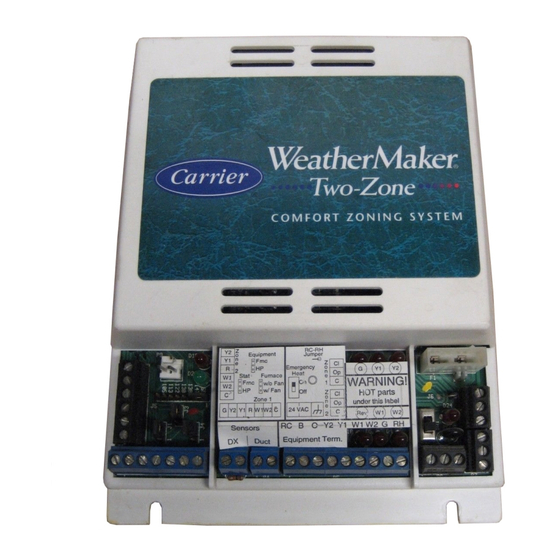
Y2
Y1
R
W1
W2
C
G Y2 Y1
HP
Fig. 1—WeatherMaker Two-Zone System
(Shown Without Cover)
5. Use separate isolated transformer to supply power to Weath-
erMaker Two-Zone Center. (40va minimum, class 2, trans-
former, field supplied)
6. Load calculations must be performed to determine equipment
size. Equipment selection is matched to block load. It is
imperative equipment is not over sized.
7. Ductwork must be designed based off the sum of peak plus 25
percent oversize. It is imperative ductwork is not under sized.
.
The WeatherMaker Two-Zone System allows the air conditioning
and heating equipment to control temperatures in 2 distinct spaces
or zones within a building. Each zone has independent temperature
settings controlled by a thermostat.
NOTE: Thermostats are purchased separately.
The comfort temperature settings can change automatically
through the use of schedules if programmable thermostats are
selected. This allows WeatherMaker Two-Zone to change the
temperature settings in zones to reflect occupancy or usage. The
WeatherMaker Two-Zone System uses motorized air volume
control dampers (also called zone dampers) to regulate the flow of
conditioned air into the zones.
Step 1—Check Equipment and Jobsite
INSPECT EQUIPMENT — File claim with shipping company,
prior to installation, if shipment is damaged or incomplete.
Form ZONEKIT-8SI
ZONEKIT2ZCAR
®
CO MF OR T ZO NIN G
SY ST EM
T'stat
Equp imt
RC-R H
Jump er
HP
Z
C1
Fnc
o
3
Fnc
Emer gency
HP
n
Op
G
Y1
Y2
Heat
e
DTO
Fnc Ht
C
1
WA RNI NG !
On
Off
w/oF
Off
Z
C1
On
w/F
HOT parts
o
under this label
n
Op
e
R W1 W2 C
24 VAC
C
Rev
2
W1 W2
Sens ors
RC B O Y2 Y1
W1 W2 G RH
Duc t
Equip ment Term .
INTRODUCTION
INSTALLATION
Pg 1
6-97
Replaces: ZONEKIT-2SI
A97292
Advertisement
Table of Contents
Troubleshooting

Related Manuals for Carrier WEATHERMAKER ZONEKIT2ZCAR


Summary of Contents for Carrier WEATHERMAKER ZONEKIT2ZCAR
- Page 1 Visit www.carrier.com Installation and Start-Up Instructions NOTE: Read the entire instruction manual before starting the installation. This symbol indicates a change since the last issue. TABLE OF CONTENTS Safety Considerations...1 Installation Considerations...1 Introduction ...1 Installation...1-4 Sequence Of Operation...4-7 Thermostat Wiring ...6-8 Care And Maintenance ...8...
-
Page 2: Round Metal Ductwork
Step 2—Wiring To prevent personal injury or possible equipment damage, disconnect the power supply before routing wire. All wiring must comply with local, state, and national codes. NOTE: Use No. 18 AWG color-coded, insulated (35°C min) wire. If thermostats are to be located more than 100 ft from the WeatherMaker Two-Zone Center as measured along the control voltage wires, use 16 AWG colored-coded wires to avoid exces- sive voltage drop. -
Page 3: Rectangular Fibrous Glass Ductwork
Fig. 5—Insulated Round Metal Ductwork S-LOCK SUPPLY AIR DUCT DRIVE Fig. 6—Rectangular Metal Ductwork 2. Properly seal joint using duct tape, mastic, or other approved method. Do not allow mastic to come in contact with actuator. 3. Insulate damper using 1-1/2-in. to 2-in. insulation. (Check your local codes.) (See Fig. -
Page 4: Installation
Step 5—Install Barometric Bypass Damper NOTE: The barometric bypass damper is a critical part of the WeatherMaker Two-Zone System for control of minimum airflow and noise reduction. It is recommended that the bypass be installed. The bypass should be installed according to local codes and SMACNA standards. -
Page 5: Thermostat Setup
HVAC problem, not a WeatherMaker Two-Zone problem. Step 6—Electronic Thermostat Connection with WeatherMaker Two-Zone Control Carrier electronic non-programmable and programmable thermo- stats can be connected to the WeatherMaker Two-Zone. See pre-sale literature for thermostat part numbers. NOTE: The zone control board is only capable of 2-stage heat and 2-stage cool operation. - Page 6 Thermostat Zone 2 ZONE 1 I/O CENTER CONNECTIONS † THERMOSTAT/SUBBASE CONNECTIONS ONLY HOOKUP "C" WHEN SUPPLIED BY THERMOSTAT † HOOKUP WHEN USING APPLICABLE TWO-STAGE THERMOSTATS WITH TWO-STAGE EQUIPMENT Fig. 12—WeatherMaker Two-Zone Circuit Board with Standard Thermostat Wiring Duct Thermostat Zone 1 Sensors Equipment †...
- Page 7 NON-PROGRAMMABLE ELECTRONIC TWO-ZONE BOARD THERMOSTAT THERMOSTAT MODEL AC INPUT 24 VAC HOT 24 VAC COMM HEAT STAGE 1 COOL STAGE 1 SINGLE-STAGE HEAT, SINGLE-STAGE COOL SEE NOTES 1 AND 3 NON-PROGRAMMABLE ELECTRONIC TWO-ZONE BOARD THERMOSTAT THERMOSTAT MODEL 2S INPUT 24 VAC HOT 24 VAC COMM HEAT STAGE 1 COOL STAGE 2...
-
Page 8: Care And Maintenance
PROGRAMMABLE ELECTRONIC TWO-ZONE BOARD THERMOSTAT THERMOSTAT MODEL AC INPUT 24 VAC HOT HEAT STAGE 1 COOL STAGE 1 24 VAC COMM OUTDOOR SINGLE-STAGE HEAT, SENSOR SINGLE-STAGE COOL CONNECTION SEE NOTES 1 AND 3 PROGRAMMABLE ELECTRONIC TWO-ZONE BOARD THERMOSTAT THERMOSTAT MODEL 2S INPUT COOL STAGE 1 HEAT STAGE 1... -
Page 9: Troubleshooting
TROUBLESHOOTING This section contains information to assist you in troubleshooting problems and errors associated with the WeatherMaker Two-Zone system. See Table 2. Step 1—System Diagram, Jumpers, and Switches NOTE: For correct control board operation, it must have either a sensor attached or a 10k resistor in place at the duct and HP inputs. Fnc—Gas/electric thermostat is installed in each zone. - Page 10 Red LED—Displays ON when fan is energized. Red LED—Displays ON when first-stage cooling is energized. Red LED—Displays ON when second-stage cooling is energized. Red LED—Displays ON when reversing valve is ener- gized. LED CODES Green flashes 1 time every sec and no other LEDs are flashing.
-
Page 11: Troubleshooting
3.000 14,323 2.944 13,681 2.889 13,071 2.833 12,493 2.777 11,942 2.721 11,418 2.666 OUTDOOR SINGLE-SPEED UNIT AIR CONDITIONER Single-Stage Furnace Two-Stage Furnace Typical Fan Coil FK4C Fan Coil OHMS VOLTS TEMP °F 10,921 2.610 10,449 2.555 10,000 2.500 9571 2.445 9164 2.391... - Page 12 TWO-ZONE SYSTEM SINGLE-STAGE FURNACE Fig. 15—Single-Stage Furnace With Single-Speed Air Conditioner TWO-ZONE SYSTEM TYPICAL FAN COIL Y/Y2 See notes 1 and 3 Fig. 17—Typical Fan Coil With Single-Speed Air Conditioner TWO-ZONE SYSTEM SINGLE-SPEED AIR CONDITIONER A97296 Fig. 16—Two-Stage or Variable-Speed Furnace...
- Page 13 AIR CONDITIONER SINGLE-STAGE TWO-ZONE SYSTEM FURNACE See note 2 Fig. 19—Single-Stage Furnace With 2-Speed Air Conditioner AIR CONDITIONER TYPICAL TWO-ZONE SYSTEM FAN COIL Y/Y2 See notes 1, 2, and 3 Fig. 21—Typical Fan Coil With 2-Speed Air Conditioner 2-SPEED TWO-ZONE SYSTEM A97300 Fig.
- Page 14 INTERFACE CONTROL TWO-ZONE SYSTEM (KHAIC0101AAA) Fig. 23—Single-Stage Furnace With Single-Speed Heat Pump INTERFACE CONTROL TWO-ZONE SYSTEM (KHAIC0101AAA) Fig. 24—Two-Stage or Variable-Speed Furnace With Single-Speed Heat Pump SINGLE-SPEED SINGLE-STAGE HEAT PUMP FURNACE OUTDOOR THERMOSTAT (KHAOT0301FST) See notes 4, 5, 6, and 7 2-STAGE OR SINGLE-SPEED VARIABLE-SPEED...
- Page 15 TWO-ZONE SYSTEM TYPICAL FAN COIL Y/Y2 See notes 1 and 3 Fig. 25—Typical Fan Coil With Single-Speed Heat Pump SINGLE-STAGE TWO-ZONE SYSTEM FURNACE See notes 2, 5, 6, 7, 9, 10, and 11 Fig. 27—Single-Stage Furnace With 2-Speed Heat Pump TWO-ZONE SYSTEM SINGLE-SPEED HEAT PUMP...
-
Page 16: Wiring Diagram Notes
11. DO NOT select "ZONE" position on 2-speed heat pump control board. In heating mode, heat pump outdoor temperature sensor will control the compressor low- and high-speed change. Copyright 1997 CARRIER Corp. • 7310 W. Morris St. • Indianapolis, IN 46231 Manufacturer reserves the right to discontinue, or change at any time, specifications or designs without notice and without incurring obligations.
Need help?
Do you have a question about the WEATHERMAKER ZONEKIT2ZCAR and is the answer not in the manual?
Questions and answers