
Related Manuals for Carrier KJR120


Summary of Contents for Carrier KJR120
- Page 1 INSTALLATION& OWNER’ S MANUAL Thank you very much for purchasing our air conditioner, Before using your air conditoner, please read this manual carefully and keep it for future reference.
- Page 2 ● This manual gives detailed description of the precautions that should be brought to your attention during operation. ● In order to ensure correct service of the wired controller please read this manual carefully before using the unit. ● For convenience of future reference, keep this manual after reading it.
-
Page 3: Table Of Contents
CONTENTS 1. SAFETY PRECAUTIONS................. 1 2. INSTALLATION ACCESSORY..............2 3. INSTALLATION METHOD.................4 4. WIRING DIAGRAM BETWEEN WIRE CONTROLLER AND AIR CONDITIONER..................7 5. SPECIFICATION..................8 6. NAME ON THE LCD OF THE WIRE CONTROLLER......9 7. NAME OF BUTTON ON THE WIRE CONTROLLER....... 10 8. -
Page 4: Safety Precautions
1. SAFETY PRECAUTIONS Read the safety precautions carefully before installing the unit. Stated below are important safety issues that must be obeyed. Means improper handling may lead to personal death or severe injury. WARNING Means improper handling may lead to personal injury or property loss. CAUTION WARNING Please entrust the distributor or professionals to install the unit. -
Page 5: Installation Accessory
2. INSTALLATION ACCESSORY Select the installation location Don’t install at the place where cover with heavy oil, vapor or sulfureted gas, otherwise, this product would be deformed that would lead to system malfunction. Preparation before installation 1. Please confirm that all the following parts you have been supply. Qty. - Page 6 2. INSTALLATION ACCESSORY Precaution of install the wire controller 1. This manual provides the installation method of wire controller. Please refer to the wiring diagram of this installation manual to wire the wire controller with indoor unit. 2. The wire controller working in low voltage loop circuit. Forbid to directly contact the cable of 220Vcommercial electricity or of 380V high voltage, and don’t wire this kind of wire in the said loop;...
-
Page 7: Installation Method
3. INSTALLATION METHOD Installation diagram Mainboard Connective wires (accessory) Fig 3-1 1. Connect the female joint of wires group from the mainboard with the male joint of connective wires group. (See Fig.3-1) 2. Please connect the other side of connective wires group with the male joint of wires group leads from wire controller. - Page 8 3. INSTALLATION METHOD Fig 3-3 Put the battery into the installationsite and make sure the positive side of the battery is in accordance with the positive side of installationsite.(See Fig.3-3) Fig 3-4...
-
Page 9: Installation Method
3. INSTALLATION METHOD 5. Adjust the length of two plastic bolts base on the length of through out from standard electric cabinet to the wall. Confirm the two bolts fixing in the cabinet are in the same length and vertical to the wall surface. 6. -
Page 10: Wiring Diagram Between Wire Controller And Air Conditioner
WIRING DIAGRAM BETWEEN WIRE CONTROLLER AND AIR CONDITIONER 1. Wiring diagram of wire controller connects with indoor unit (See fig 4-1) Indoor unit electric cabinet Mainboard Shielded 4-core cable Insert of the electric mainboard CN40 The rear side of wire controller Fig 4-1... -
Page 11: Specification
5. SPECIFICATION DC 5V/DC 12V Input voltage -5~43℃(23~110℉) Ambient temperature RH40%~RH90% Ambient humidity All the pictures in this manual are for explanation purpose only. Your wire controller may be slightly different .The actual shape shall prevail. -
Page 12: Name On The Lcd Of The Wire Controller
6. NAME ON THE LCD OF THE WIRE CONTROLLER 1 Operation mode indication 8 PTC function indication 2 Fan speed indication 9 C° / F° indication 3 Left-right swing indication 10 Temperature display 4 Up-down swing indication 11 Lock indication 5 Faceplate function indication 12 Room temperature indication 6 Main unit and secondary unit indication... -
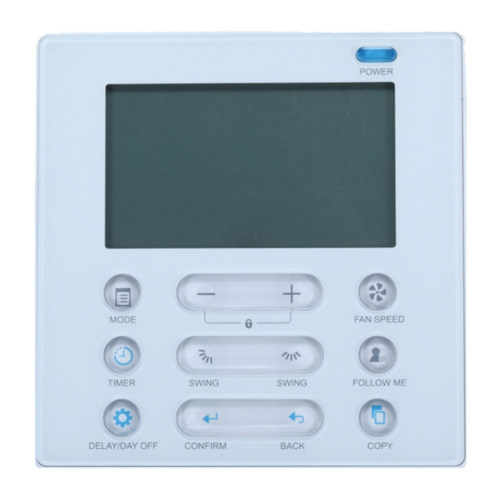
Page 13: Name Of Button On The Wire Controller
7. NAME OF THE BUTTON ON THE WIRE CONTROLLER swing swing... - Page 14 7. NAME OF THE BUTTON ON THE WIRE CONTROLLER 1 Power Button 2 Mode(A/B) Button 3 Adjust Button 4 Fan speed Button 5 Up-down Airflow Direction and Swing Button 6 Left-right Airflow Swing Button 7 Follow me(PTC) Button 8 Timer Button 9 Day off(Del) Button 10 Confirm Button 11 Back Button...
-
Page 15: Preparatory Operation
8. PREPARATORY OPERATION Set the current day and time Press the Timer button for 3 seconds or more. The timer display will flash. Press the button “ + ” or “ - ” to set the date. The selected date will flash. The date setting is finished and the time setting is prepared after pressing Timer button or there is no pressing button in 10 seconds. -
Page 16: Operation
9. OPERATION To start/stop operation Press the Power button. Operation lamp Air conditioner ON :Lit brightly Air conditioner OFF:Not lit To set the operation mode Operation mode setting Press the Mode button to set the operation mode. (Heat function is invalid for cool only type unit) Room temperature setting Press the button“... - Page 17 9. OPERATION Fan speed setting Press the Fan speed button to set the fan speed. (This button is unavailable when in the mode of Auto or Dry) Room temperature sensor selection Indoor Unit Press the Follow me/PTC button to select whether the room temperature is detected at the indoor unit or the wire controller.
- Page 18 9. OPERATION PTC function (on some models) Press the Follow me/PTC button for 2 seconds or more to activate the PTC function,when the unit is under the Heat mode. Press the buttons again for 2 seconds or more to deactivate the PTC function.
- Page 19 9. OPERATION Faceplate function (on some models) 1.When the unit is off,Press the Mode(A/B) button long to activate the faceplate function.The mark will flash. The F2 mark appears when the faceplate is adjusted. 2. Push the Mode(A/B) button to select Unit A or Unit B, the wire controller select in a sequence that goes from(this step do not need to perform if the wire controller is connected with one unit only): 3.
- Page 20 9. OPERATION Up-Down airflow direction and swing (on some models) button to adjust the Up-down airflow direction. 1.When press the button once and quickly ,the Up-down airflow direction setting feature of the louver is activated.The moving angle of the louver is 6° for each press.Keep pressing the button to move the louver to the desired position.
-
Page 21: Timer Functions
10. TIMER FUNCTIONS WEEKLY timer Use this timer function to set operating times for each day of the week. On timer Use this timer function to start air conditioner operation.The timer operates and air conditioner operation starts after the time has passed. Off timer Use this timer function to stop air conditioner operation.The timer operates and air conditioner operation stops after the time has passed. - Page 22 10. TIMER FUNCTIONS To set the On or Off TIMER Press the Timer button to select the timer No display Press the Confirm button and the Clock display is flashing. confirm ex.Off timer set at PM 6:00 Press the button “ + ” or “ - ” to set the time. After the time is set, the timer will start or stop automatically.
- Page 23 10. TIMER FUNCTIONS To set the On and Off TIMER Press the Timer button to select the timer Press the Confirm button and the Clock display is flashing. confirm confirm Press the button “ + ” or “ - ” to set the time of On timer,and then press the Confirm button to confirm the setting.
-
Page 24: Weekly Timer
11. WEEKLY TIMER Weekly timer setting timer confirm Press the Timer button to select the , and then press the Confirm button to confirm. Day of the week setting confirm Press the button “ + ” and “ - ” to select the day of the week.and then press the CONFIRM button to confirm the setting. - Page 25 11. WEEKLY TIMER Up to 8 time scales can be setted in one day.Mode,temperature and fan speed in different time scale can be setted. ex.Tuesday time scale 1 Time setting Press the button “ + ” and “ - ” to set the time.and then press the Confirm button to confirm the setting.
- Page 26 11. WEEKLY TIMER Press the button “ + ” and “ - ” to set the room temperature .and then press the Confirm button to confirm the setting. NOTE:This setting is unavailable when in the mode of Fan or Off. Fan speed setting confirm Press the button “...
- Page 27 11. WEEKLY TIMER WEEKLY timer operation To start Press the Timer button to select the ,and the the timer starts automatically. To cancel Press the Power button to cancel the timer mode. The timer mode can also be canceled by changing the timer mode using the Timer button.
- Page 28 11. WEEKLY TIMER Press the Day off button to set the DAY OFF. mark is hidden ex.The DAY OFF is set for Wednesday The DAY OFF can be setted for other days by repeating the steps 2 and 3. Press the Back button to back to the weekly timer. To cancel:Follow the same procedures as those for setup。...
- Page 29 11. WEEKLY TIMER Press the Copy button,the letter “CY” will be shown on the LCD. Press the button “ + ” and “ - ” to select the day to copy to. Press the Copy button to confirm . mark flashes quickly ex.
- Page 30 11. WEEKLY TIMER Delete the time scale in one day. During the weekly timer, press the Confirm button. Press the button “ + ” and “ - ” to select the day of the week.and then press the Confirm button to confirm the setting. Press the button “...
-
Page 31: Fault Alarm Handing
12. FAULT ALARM HANDING If the system does not properly operate except the above mentioned cases or the above mentioned malfunctions is evident, investigate the system according to the following procedures. D ISPLAY MALFU N C T ION & PROT EC T ION D EFIN E DIGITAL TUBE Error of communication between wire controler and indoor unit...
Need help?
Do you have a question about the KJR120 and is the answer not in the manual?
Questions and answers
How to change up to heat