Table of Contents
Advertisement
Quick Links
Advertisement
Table of Contents

Related Manuals for Rohde & Schwarz RT-ZS60


Summary of Contents for Rohde & Schwarz RT-ZS60
- Page 1 ® R&S RT-ZS60 Active Voltage Probe User Manual (>B×Z2) 1418.7342.02 ─ 01...
- Page 2 Rohde & Schwarz GmbH & Co. KG. Trade names are trademarks of the owners. ® The following abbreviations are used in this manual: R&S RT-ZS60 is abbreviated as R&S RT-ZS60. ® ® R&S ProbeMeter is abbreviated as R&S ProbeMeter. R&S...
- Page 3 Basic Safety Instructions Always read through and comply with the following safety instructions! All plants and locations of the Rohde & Schwarz group of companies make every effort to keep the safety standards of our products up to date and to offer our customers the highest possible degree of safety.
- Page 4 Basic Safety Instructions systems and all accessories. For product-specific information, see the data sheet and the product documentation. Symbols and safety labels Symbol Meaning Symbol Meaning Notice, general danger location ON/OFF supply voltage Observe product documentation Caution when handling heavy Standby indication equipment Danger of electric shock...
- Page 5 Basic Safety Instructions Signal words and their meaning The following signal words are used in the product documentation in order to warn the reader about risks and dangers. Indicates an imminently hazardous situation which, if not avoided, will result in death or serious injury. Indicates a potentially hazardous situation which, if not avoided, could result in death or serious injury.
- Page 6 Basic Safety Instructions 2. Do not place the product on surfaces, vehicles, cabinets or tables that for reasons of weight or stability are unsuitable for this purpose. Always follow the manufacturer's installation instructions when installing the product and fastening it to objects or structures (e.g. walls and shelves). An installation that is not carried out as described in the product documentation could result in personal injury or even death.
- Page 7 Basic Safety Instructions 5. Never use the product if the power cable is damaged. Check the power cables on a regular basis to ensure that they are in proper operating condition. By taking appropriate safety measures and carefully laying the power cable, ensure that the cable cannot be damaged and that no one can be hurt by, for example, tripping over the cable or suffering an electric shock.
- Page 8 Basic Safety Instructions 16. Unless specified otherwise, products are not liquid-proof (see also section "Operating states and operating positions", item 1). Therefore, the equipment must be protected against penetration by liquids. If the necessary precautions are not taken, the user may suffer electric shock or the product itself may be damaged, which can also lead to personal injury.
- Page 9 Basic Safety Instructions 6. Should a fire occur, the product may release hazardous substances (gases, fluids, etc.) that can cause health problems. Therefore, suitable measures must be taken, e.g. protective masks and protective clothing must be worn. 7. Laser products are given warning labels that are standardized according to their laser class.
- Page 10 Basic Safety Instructions 1. Cells must not be taken apart or crushed. 2. Cells or batteries must not be exposed to heat or fire. Storage in direct sunlight must be avoided. Keep cells and batteries clean and dry. Clean soiled connectors using a dry, clean cloth.
- Page 11 Basic Safety Instructions 3. If you use the product in a vehicle, it is the sole responsibility of the driver to drive the vehicle safely and properly. The manufacturer assumes no responsibility for accidents or collisions. Never use the product in a moving vehicle if doing so could distract the driver of the vehicle.
- Page 12 Instrucciones de seguridad elementales ¡Es imprescindible leer y cumplir las siguientes instrucciones e informaciones de seguridad! El principio del grupo de empresas Rohde & Schwarz consiste en tener nuestros productos siempre al día con los estándares de seguridad y de ofrecer a nuestros clientes el máximo grado de seguridad.
- Page 13 Instrucciones de seguridad elementales Tener en cuenta las informaciones de seguridad sirve para evitar en lo posible lesiones o daños por peligros de toda clase. Por eso es imprescindible leer detalladamente y comprender por completo las siguientes informaciones de seguridad antes de usar el producto, y respetarlas durante el uso del producto. Deberán tenerse en cuenta todas las demás informaciones de seguridad, como p.
- Page 14 Instrucciones de seguridad elementales Símbolo Significado Símbolo Significado Aviso: Cuidado en el manejo de Distintivo de la UE para la dispositivos sensibles a la eliminación por separado de electrostática (ESD) dispositivos eléctricos y electrónicos Más información en la sección "Eliminación/protección del medio ambiente", punto 2.
- Page 15 Instrucciones de seguridad elementales Estados operativos y posiciones de funcionamiento El producto solamente debe ser utilizado según lo indicado por el fabricante respecto a los estados operativos y posiciones de funcionamiento sin que se obstruya la ventilación. Si no se siguen las indicaciones del fabricante, pueden producirse choques eléctricos, incendios y/o lesiones graves con posible consecuencia de muerte.
- Page 16 Instrucciones de seguridad elementales 2. Los productos de la clase de protección I con alimentación móvil y enchufe individual solamente podrán enchufarse a tomas de corriente con contacto de seguridad y con conductor de protección conectado. 3. Queda prohibida la interrupción intencionada del conductor de protección, tanto en la toma de corriente como en el mismo producto.
- Page 17 Instrucciones de seguridad elementales 10. Para la conexión con dispositivos informáticos como un PC o un ordenador industrial, debe comprobarse que éstos cumplan los estándares IEC60950- 1/EN60950-1 o IEC61010-1/EN 61010-1 válidos en cada caso. 11. A menos que esté permitido expresamente, no retire nunca la tapa ni componentes de la carcasa mientras el producto esté...
- Page 18 Instrucciones de seguridad elementales Funcionamiento 1. El uso del producto requiere instrucciones especiales y una alta concentración durante el manejo. Debe asegurarse que las personas que manejen el producto estén a la altura de los requerimientos necesarios en cuanto a aptitudes físicas, psíquicas y emocionales, ya que de otra manera no se pueden excluir lesiones o daños de objetos.
- Page 19 Instrucciones de seguridad elementales 7. Los productos con láser están provistos de indicaciones de advertencia normalizadas en función de la clase de láser del que se trate. Los rayos láser pueden provocar daños de tipo biológico a causa de las propiedades de su radiación y debido a su concentración extrema de potencia electromagnética.
- Page 20 Instrucciones de seguridad elementales 1. No deben desmontarse, abrirse ni triturarse las celdas. 2. Las celdas o baterías no deben someterse a calor ni fuego. Debe evitarse el almacenamiento a la luz directa del sol. Las celdas y baterías deben mantenerse limpias y secas.
- Page 21 Instrucciones de seguridad elementales 3. Si se utiliza el producto dentro de un vehículo, recae de manera exclusiva en el conductor la responsabilidad de conducir el vehículo de manera segura y adecuada. El fabricante no asumirá ninguna responsabilidad por accidentes o colisiones.
- Page 22 Safety Instructions - Informaciones de seguridad Safety Instructions for Active Voltage Probes When handling active voltage probes, the following basic rules must be observed. Prior to using an active voltage probe, read the applicable manual including the safety instructions. Keep the safety instructions and the product documentation in a safe place and pass them on to other users.
- Page 23 Safety Instructions - Informaciones de seguridad Informaciones de seguridad para el uso de sondas de voltaje activas A la hora de manejar una sonda de voltaje activa, es necesario seguir las siguientes instrucciones de uso básicas. Lea primero el manual de manejo correspondiente incluyendo las instrucciones de seguridad.
- Page 24 Customer Support Technical support – where and when you need it For quick, expert help with any Rohde & Schwarz equipment, contact one of our Customer Support Centers. A team of highly qualified engineers provides telephone support and will work with you to find a solution to your query on any aspect of the operation, programming or applications of Rohde &...
-
Page 25: Table Of Contents
® Contents R&S RT-ZS60 Contents 1 Product Description..............5 1.1 Key Features and Key Characteristics..........5 1.1.1 Key Characteristics.................5 1.1.2 Key Features...................6 1.2 Unpacking the Instrument..............7 1.2.1 Inspecting the Contents................7 1.3 Description of the Probe..............8 1.3.1 Probe Head.....................8 1.3.2 Probe Box....................9 1.4 Accessories and Items...............10 1.4.1 Accessories Supplied................11... - Page 26 ® Contents R&S RT-ZS60 4.1.1 Bandwidth.....................30 4.1.2 Connection Inductance.................32 4.2 Performance with Different Connection Types........33 4.3 Signal Loading of the Input Signal............35 4.3.1 Input Impedance...................35 4.4 Probing Philosophy................38 5 Maintenance and Service............40 5.1 Service Strategy..................40 5.2 Returning the Probe for Servicing............40 5.3 Cleaning....................41...
-
Page 27: Product Description
(DUT), not impairing the extremely short rise time and the low input capacitance of the R&S RT-ZS60. Provided with special features such as the R&S ProbeMeter and the micro button, the R&S RT-ZS60 is designed to meet tomorrow's challenges in probing. -
Page 28: Key Features
® Product Description R&S RT-ZS60 Key Features and Key Characteristics Bandwidth DC to 6 GHz Dynamic range ±8 V with ±10 V offset capability 16 V AC (V Input resistance 1 MΩ Input capacitance 0.3 pF R&S ProbeMeter, measurement error <0.1 %... -
Page 29: Unpacking The Instrument
Rohde & Schwarz service center. Keep the package and cushioning mate- rial for inspection. ● Inspect the probe. If there is any damage or defect, or if the R&S RT-ZS60 active voltage probe does not operate properly, notify your Rohde & Schwarz service center. ● Inspect the accessories. -
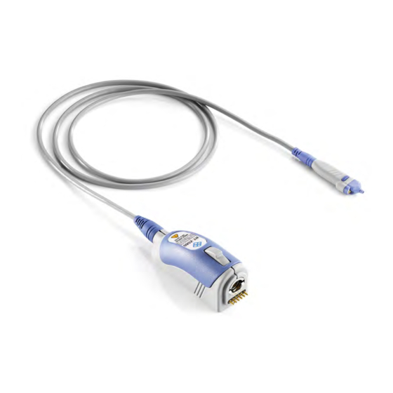
Page 30: Description Of The Probe
® Product Description R&S RT-ZS60 Description of the Probe Description of the Probe The probe consists of the probe head for connection to the DUT, the probe box for connection to the oscilloscope, and the probe cable. 1.3.1 Probe Head The small and lightweight probe head is designed for easy handling and high-per- formance measurements. -
Page 31: Probe Box
Description of the Probe Special accessories for signal socket The signal socket of the R&S RT-ZS60 has a special design to ensure optimal performance. The signal socket is not compatible to standard accessories based on 0.64 mm (25 mil) square pins or 0.8 mm (35 mil) round pins. Use only special accessories for R&S RT-ZS60 provided by Rohde &... -
Page 32: Accessories And Items
® Product Description R&S RT-ZS60 Accessories and Items Accessories and Items The figure below shows all accessories that are available for the R&S RT-ZS60 active voltage probe. lead, 15 cm / 5.9 in lead 6 cm / 2.4 in ground adapter,... -
Page 33: Accessories Supplied
® Product Description R&S RT-ZS60 Accessories and Items 1.4.1 Accessories Supplied The following table shows the accessories supplied with the R&S RT-ZS60 active voltage probe. Table 1-1: Accessories supplied Item Quantity Description Signal pin, solder in Signal pin Signal adapter, square pin... - Page 34 ® Product Description R&S RT-ZS60 Accessories and Items Item Quantity Description Lead, 6 cm / 2.4 in Lead, 15 cm / 5.9 in Mini clip Micro clip Marker band kit Carrying case with foam inlay User Manual 1418.7342.02 ─ 01...
-
Page 35: Optional Accessories
® Product Description R&S RT-ZS60 Accessories and Items 1.4.2 Optional Accessories If the included accessories do not meet individual customer requirements, Rohde & Schwarz offers different accessory sets for sale. Table 1-2: R&S RT-ZA4 Mini Clips Item Quantity Description Mini clip This set contains mini clips. -
Page 36: Service Accessories
The service kit includes all adapters and accessories to match the probe to the required measuring instruments. The R&S RT-ZS60 Service Manual is included in the ser- vice kit CD-ROM. Table 1-7: R&S RT-ZS60 Service Manual... -
Page 37: Putting Into Operation
RT-ZS60 Putting into Operation The R&S RT-ZS60 active voltage probe has been designed to withstand a moderate amount of physical and electrical stress. You should treat the probe with care. It can be damaged if excessive force is applied to the probe tip. -
Page 38: Installation
The following two methods of ESD protection may be used together or sep- arately: ● Wrist strap with cord to ground connection ● Conductive floor mat and heel strap combination Installation This section provides a quick introduction to the use of the R&S RT-ZS60 active voltage probe. User Manual 1418.7342.02 ─ 01... -
Page 39: Connecting The Probe To The R&S Rto Oscilloscope
2.1.1 Connecting the Probe to the R&S RTO Oscilloscope The R&S RT-ZS60 active voltage probe has been designed for use with R&S RTO oscilloscopes. ► Connect the probe box (1) to the Rohde & Schwarz probe interface of the base unit (2). -
Page 40: Auto Zero
The waveform is set to 0 V on the horizontal centerline of the oscilloscope. The zero error of the R&S RT-ZS60 probe itself is very small, typically in the range of a few hundred micro volts referred to the probe input. However, differences in DUT and oscilloscope ground levels may cause larger zero errors to be displayed on the oscilloscope's screen. -
Page 41: Micro Button
® Putting into Operation R&S RT-ZS60 Micro Button Alternatively, Auto Zero can be started in the dialog box of the R&S RTO: ► "Vertical" menu > "Probe Setup" > "Ch" tab > "Auto zero" Micro Button The micro button provides easy and quick access to important functions of the R&S RTO. - Page 42 ® Putting into Operation R&S RT-ZS60 Offset Compensation Fig. 2-2: Offset compensation voltage and dynamic range To set offset compensation on the front panel: 1. Press the Vertical Position knob until the "Offset" setup is shown on the display. 2. Turn the Vertical Position knob.
-
Page 43: R&S Probemeter
® Putting into Operation R&S RT-ZS60 R&S ProbeMeter To assign "Set offset to mean" to the micro button: ► "Vertical" menu > "Probe Setup" > "Ch" tab > "Micro button action" = "Set offset to mean" The maximum input voltage is ±30 V. A higher input voltage may destroy the probe. - Page 44 ® Putting into Operation R&S RT-ZS60 R&S ProbeMeter The R&S ProbeMeter enables the ground-referenced measurement of voltages. A difference in the ground levels of oscilloscope and DUT can cause an unwanted zero error. Should this happen, use the Auto Zero function (refer to ...
-
Page 45: Connecting The Probe To The Dut
® Connecting the Probe to the DUT R&S RT-ZS60 Connecting the Probe to the DUT This chapter describes the different ways of connecting the probe to the DUT. In addition, the accessories supplied are described and their use is explained. - Page 46 RT-ZS60 Signal pin, solder in, and ground pin, solder-in Using two solder-in pins for ground and signal, the R&S RT-ZS60 is soldered directly into the circuit. The pins can be exchanged on the probe and can remain in the circuit. Thus, you can plug the probe on different test points.
- Page 47 ® Connecting the Probe to the DUT R&S RT-ZS60 Signal adapter, square pin, and ground adapter, square pin Using signal and ground adapters, the probe can be connected directly to a pin strip. The sockets are compatible with 0.64 mm (25 mil) square pins and 0.6 mm to 0.8 mm...
- Page 48 In addition, it allows micro and mini clips to be connected to the probe. Connencting a lead to the signal socket of the R&S RT-ZS60 requires a signal adapter, square pin. Length: Short lead: 6 mm (236 mil) Long lead: 15 mm (591 mil) User Manual 1418.7342.02 ─...
- Page 49 ® Connecting the Probe to the DUT R&S RT-ZS60 Clips Mini and micro clips The mini clip is designed for probing large IC pins, wires and through-hole components. The micro clip is designed for probing IC pins and thin wires in fine-pitch applications.
-
Page 50: Measurement Principles
RT-ZS60 Measurement Principles The R&S RT-ZS60 active voltage probe provides an electrical connection between the DUT and the oscilloscope. The probe transfers the voltage of the electrical signal tapped off the DUT to the oscilloscope, where it is displayed graphically. Although... - Page 51 ® Measurement Principles R&S RT-ZS60 Fig. 4-1: Equivalent circuit model of the R&S RT-ZS60 probe Table 4-1: Designations Abbreviation Description Voltage at the test point without probe connected Voltage at the test point with probe connected, corresponds to the input voltage of the probe...
-
Page 52: Signal Integrity Of The Transferred Signal
The following explanations refer to the probe itself, but can also be applied to the entire system. Fig. 4-2: Amplitude frequency response of the R&S RT-ZS60 The bandwidth ● Specifies the maximum frequency at which a purely sinusoidal signal is still transferred at 70 % (–3 dB) of its amplitude. - Page 53 The f igure 4-2 shows the typical amplitude fre- quency response of an R&S RT-ZS60 active voltage probe. All frequency compo- nents are transferred with the same gain so that the input signal is displayed without distortion.
-
Page 54: Connection Inductance
® Measurement Principles R&S RT-ZS60 Signal Integrity of the Transferred Signal 4.1.2 Connection Inductance The connection inductance L is caused by connecting the probe to the DUT. In contrast to the probe-specific bandwidth, the connection inductance mainly depends on the type of connection that the user selects. -
Page 55: Performance With Different Connection Types
® Measurement Principles R&S RT-ZS60 Performance with Different Connection Types Performance with Different Connection Types The t able 4-2 shows three types of connection between probe and DUT as well as the associated rise times, bandwidths, input impedances and overshoots. - Page 56 Measurement Principles R&S RT-ZS60 Performance with Different Connection Types Fig. 4-5: Step response of the R&S RT-ZS60 with a type 1 connection Fig. 4-6: Step response of the R&S RT-ZS60 with a type 2 connection User Manual 1418.7342.02 ─ 01...
-
Page 57: Signal Loading Of The Input Signal
RT-ZS60 Signal Loading of the Input Signal Fig. 4-7: Step response of the R&S RT-ZS60 with a type 3 connection Signal Loading of the Input Signal The previous section dealt with the transfer function and step response of the probe. - Page 58 Fig. 4-8: Magnitude of the input impedance of the R&S RT-ZS60 probe as a function of fre- quency User Manual 1418.7342.02 ─ 01...
- Page 59 Measurement Principles R&S RT-ZS60 Signal Loading of the Input Signal Fig. 4-9: Signal loading caused by the R&S RT-ZS60 probe at an effective source impedance of 25 Ω 4.3.1.1 Input Resistance R The input resistance determines the loading of the DUT at DC and very low fre- quencies (<...
-
Page 60: Probing Philosophy
® Measurement Principles R&S RT-ZS60 Probing Philosophy 4.3.1.3 RF Resistance R and R and R (summarized R ) determine the input impedance in the frequency range from 20 MHz to 2 GHz. Due to the constantly high input impedance of 300 Ω... - Page 61 , as shown in of the unloaded signal V f igure 4-10. Fig. 4-10: Unloaded and loaded input signal and step response using the example of R&S RT-ZS60 User Manual 1418.7342.02 ─ 01...
-
Page 62: Maintenance And Service
Returning the Probe for Servicing Use the original packaging to return the R&S RT-ZS60 active voltage probe to your Rohde & Schwarz service center. If you cannot use the original packaging, consider the following: 1. -
Page 63: Cleaning
® Maintenance and Service R&S RT-ZS60 Cleaning Cleaning To clean the exterior of the probe, use a soft cloth moistened with either distilled water or isopropyl alcohol. Before using the probe again, make sure to dry it com- pletely. Instrument damage caused by cleaning agents Cleaning agents contain substances that may damage the instrument;... -
Page 64: Functional Check
To verify compliance with the probe specifications, it is necessary to run an inde- pendent performance test. This test is described in detail in the R&S RT-ZS60 ser- vice manual. The performance test also requires the R&S RT-ZK2 service kit. -
Page 65: Initialization
"Vertical" menu > "Probe Setup" > "Ch1" tab Measurement: If initialization is correct, the following values are displayed on the "Setup" tab of the "Probes" dialog box for the R&S RT-ZS60: Type: active single ended Name: R&S RT-ZS60 Probe attenuation: 10:1 Bandwidth: 6.0 GHz... -
Page 66: Dc Offset
® Functional Check R&S RT-ZS60 DC Offset DC Offset The zero error of the probe-oscilloscope system and the zero error of the R&S Pro- beMeter are checked. ● Test setup: Probe connected to CH1 of the R&S RTO oscilloscope ●... -
Page 67: Dc Accuracy
® Functional Check R&S RT-ZS60 DC Accuracy DC Accuracy The gain of the probe-oscilloscope system and the accuracy of the integrated DC voltmeter are checked. ● Test setup: Probe connected to CH1 of the R&S RTO oscilloscope ● INPUT HI/LO of the DMM connected to OUTPUT HI/LO of the DC voltage source by banana leads ●... -
Page 68: Offset Compensation
® Functional Check R&S RT-ZS60 Offset Compensation ● Measurement: Set the voltage on the DC voltage source so that the DMM displays exactly +5.000 V ● Check displayed values in the "Measurement Results" box: Mean: +5 V ± 250 mV ProbeMeter: +5 V ±... -
Page 69: Index
® Index R&S RT-ZS60 Index Accessories ..........11 Offset compensation ......19 Auto Zero ..........18 Pins Bandwidth .......... 6, 30 Inserting and removing ...... 23 Usage ..........23 Probe Calibration .......... 41 Cleaning ..........41 Cleaning ..........41 Clips ..........13, 27 Connection ........
Need help?
Do you have a question about the RT-ZS60 and is the answer not in the manual?
Questions and answers