
Related Manuals for Rohde & Schwarz R&S RT-ZD01


Summary of Contents for Rohde & Schwarz R&S RT-ZD01
- Page 1 www.allice.de Allice Messtechnik GmbH ® R&S RT-ZD01 High Voltage Differential Probe User Manual (>F7P2) 1422.0732.02 ─ 02...
- Page 2 www.allice.de Allice Messtechnik GmbH ® This User Manual describes the following R&S RT-ZD models and options: ● R&S ® RT-ZD01 (1422.0703.02) © 2014 Rohde & Schwarz GmbH & Co. KG Mühldorfstr. 15, 81671 München, Germany Phone: +49 89 41 29 - 0 Fax: +49 89 41 29 12 164 E-mail: info@rohde-schwarz.com...
- Page 3 www.allice.de Allice Messtechnik GmbH Basic Safety Instructions Always read through and comply with the following safety instructions! All plants and locations of the Rohde & Schwarz group of companies make every effort to keep the safety standards of our products up to date and to offer our customers the highest possible degree of safety.
- Page 4 www.allice.de Allice Messtechnik GmbH Basic Safety Instructions systems and all accessories. For product-specific information, see the data sheet and the product documentation. Safety labels on products The following safety labels are used on products to warn against risks and dangers. Symbol Meaning Symbol...
- Page 5 www.allice.de Allice Messtechnik GmbH Basic Safety Instructions Signal words and their meaning The following signal words are used in the product documentation in order to warn the reader about risks and dangers. Indicates a hazardous situation which, if not avoided, will result in death or serious injury.
- Page 6 www.allice.de Allice Messtechnik GmbH Basic Safety Instructions 2. Do not place the product on surfaces, vehicles, cabinets or tables that for reasons of weight or stability are unsuitable for this purpose. Always follow the manufacturer's installation instructions when installing the product and fastening it to objects or structures (e.g.
- Page 7 www.allice.de Allice Messtechnik GmbH Basic Safety Instructions 5. Never use the product if the power cable is damaged. Check the power cables on a regular basis to ensure that they are in proper operating condition. By taking appropriate safety measures and carefully laying the power cable, ensure that the cable cannot be damaged and that no one can be hurt by, for example, tripping over the cable or suffering an electric shock.
- Page 8 www.allice.de Allice Messtechnik GmbH Basic Safety Instructions 16. Unless specified otherwise, products are not liquid-proof (see also section "Operating states and operating positions", item 1). Therefore, the equipment must be protected against penetration by liquids. If the necessary precautions are not taken, the user may suffer electric shock or the product itself may be damaged, which can also lead to personal injury.
- Page 9 www.allice.de Allice Messtechnik GmbH Basic Safety Instructions 6. Should a fire occur, the product may release hazardous substances (gases, fluids, etc.) that can cause health problems. Therefore, suitable measures must be taken, e.g. protective masks and protective clothing must be worn. 7.
- Page 10 www.allice.de Allice Messtechnik GmbH Basic Safety Instructions Batteries and rechargeable batteries/cells If the information regarding batteries and rechargeable batteries/cells is not observed either at all or to the extent necessary, product users may be exposed to the risk of explosions, fire and/or serious personal injury, and, in some cases, death.
- Page 11 www.allice.de Allice Messtechnik GmbH Basic Safety Instructions etc. The user is responsible for securely fastening the products to or on the means of transport or lifting. Observe the safety regulations of the manufacturer of the means of transport or lifting. Noncompliance can result in personal injury or material damage.
- Page 12 www.allice.de Allice Messtechnik GmbH Instrucciones de seguridad elementales Instrucciones de seguridad elementales ¡Es imprescindible leer y cumplir las siguientes instrucciones e informaciones de seguridad! El principio del grupo de empresas Rohde & Schwarz consiste en tener nuestros productos siempre al día con los estándares de seguridad y de ofrecer a nuestros clientes el máximo grado de seguridad.
- Page 13 www.allice.de Allice Messtechnik GmbH Instrucciones de seguridad elementales Tener en cuenta las informaciones de seguridad sirve para evitar en lo posible lesiones o daños por peligros de toda clase. Por eso es imprescindible leer detalladamente y comprender por completo las siguientes informaciones de seguridad antes de usar el producto, y respetarlas durante el uso del producto.
- Page 14 www.allice.de Allice Messtechnik GmbH Instrucciones de seguridad elementales Símbolo Significado Símbolo Significado Aviso: Cuidado en el manejo de Distintivo de la UE para la dispositivos sensibles a la eliminación por separado de electrostática (ESD) dispositivos eléctricos y electrónicos Más información en la sección "Eliminación/protección del medio ambiente", punto 2.
- Page 15 www.allice.de Allice Messtechnik GmbH Instrucciones de seguridad elementales Estados operativos y posiciones de funcionamiento El producto solamente debe ser utilizado según lo indicado por el fabricante respecto a los estados operativos y posiciones de funcionamiento sin que se obstruya la ventilación. Si no se siguen las indicaciones del fabricante, pueden producirse choques eléctricos, incendios y/o lesiones graves con posible consecuencia de muerte.
- Page 16 www.allice.de Allice Messtechnik GmbH Instrucciones de seguridad elementales 2. Los productos de la clase de protección I con alimentación móvil y enchufe individual solamente podrán enchufarse a tomas de corriente con contacto de seguridad y con conductor de protección conectado. 3.
- Page 17 www.allice.de Allice Messtechnik GmbH Instrucciones de seguridad elementales 10. Para la conexión con dispositivos informáticos como un PC o un ordenador industrial, debe comprobarse que éstos cumplan los estándares IEC60950- 1/EN60950-1 o IEC61010-1/EN 61010-1 válidos en cada caso. 11. A menos que esté permitido expresamente, no retire nunca la tapa ni componentes de la carcasa mientras el producto esté...
- Page 18 www.allice.de Allice Messtechnik GmbH Instrucciones de seguridad elementales Funcionamiento 1. El uso del producto requiere instrucciones especiales y una alta concentración durante el manejo. Debe asegurarse que las personas que manejen el producto estén a la altura de los requerimientos necesarios en cuanto a aptitudes físicas, psíquicas y emocionales, ya que de otra manera no se pueden excluir lesiones o daños de objetos.
- Page 19 www.allice.de Allice Messtechnik GmbH Instrucciones de seguridad elementales 7. Los productos con láser están provistos de indicaciones de advertencia normalizadas en función de la clase de láser del que se trate. Los rayos láser pueden provocar daños de tipo biológico a causa de las propiedades de su radiación y debido a su concentración extrema de potencia electromagnética.
- Page 20 www.allice.de Allice Messtechnik GmbH Instrucciones de seguridad elementales Baterías y acumuladores o celdas Si no se siguen (o se siguen de modo insuficiente) las indicaciones en cuanto a las baterías y acumuladores o celdas, pueden producirse explosiones, incendios y/o lesiones graves con posible consecuencia de muerte. El manejo de baterías y acumuladores con electrolitos alcalinos (p.
- Page 21 www.allice.de Allice Messtechnik GmbH Instrucciones de seguridad elementales 2. Las asas instaladas en los productos sirven solamente de ayuda para el transporte del producto por personas. Por eso no está permitido utilizar las asas para la sujeción en o sobre medios de transporte como p. ej. grúas, carretillas elevadoras de horquilla, carros etc.
- Page 22 www.allice.de Allice Messtechnik GmbH Instrucciones de seguridad elementales 4. En caso de que durante el trato del producto se formen sustancias peligrosas o combustibles que deban tratarse como residuos especiales (p. ej. refrigerantes o aceites de motor con intervalos de cambio definidos), deben tenerse en cuenta las indicaciones de seguridad del fabricante de dichas sustancias y las normas regionales de eliminación de residuos.
- Page 23 www.allice.de Allice Messtechnik GmbH Grundlegende Sicherheitshinweise Lesen und beachten Sie unbedingt die nachfolgenden Anweisungen und Sicherheitshinweise! Alle Werke und Standorte der Rohde & Schwarz Firmengruppe sind ständig bemüht, den Sicherheitsstandard unserer Produkte auf dem aktuellsten Stand zu halten und unseren Kunden ein höchstmögliches Maß an Sicherheit zu bieten. Unsere Produkte und die dafür erforderlichen Zusatzgeräte werden entsprechend der jeweils gültigen Sicherheitsvorschriften gebaut und geprüft.
- Page 24 www.allice.de Allice Messtechnik GmbH Grundlegende Sicherheitshinweise Die Einhaltung der Sicherheitshinweise dient dazu, Verletzungen oder Schäden durch Gefahren aller Art auszuschließen. Hierzu ist es erforderlich, dass die nachstehenden Sicherheitshinweise vor der Benutzung des Produkts sorgfältig gelesen und verstanden sowie bei der Benutzung des Produkts beachtet werden. Sämtliche weitere Sicherheitshinweise wie z.B.
- Page 25 www.allice.de Allice Messtechnik GmbH Grundlegende Sicherheitshinweise Symbol Bedeutung Symbol Bedeutung Achtung beim Umgang mit EU-Kennzeichnung für die elektrostatisch gefährdeten getrennte Sammlung von Elektro- Bauelementen und Elektronikgeräten Weitere Informationen in Abschnitt "Entsorgung / Umweltschutz", Punkt 2. Warnung vor Laserstrahl Weitere Informationen in Abschnitt "Betrieb", Punkt 7.
- Page 26 www.allice.de Allice Messtechnik GmbH Grundlegende Sicherheitshinweise Betriebszustände und Betriebslagen Das Produkt darf nur in den vom Hersteller angegebenen Betriebszuständen und Betriebslagen ohne Behinderung der Belüftung betrieben werden. Werden die Herstellerangaben nicht eingehalten, kann dies elektrischen Schlag, Brand und/oder schwere Verletzungen von Personen, unter Umständen mit Todesfolge, verursachen.
- Page 27 www.allice.de Allice Messtechnik GmbH Grundlegende Sicherheitshinweise 3. Jegliche absichtliche Unterbrechung des Schutzleiters, sowohl in der Zuleitung als auch am Produkt selbst, ist unzulässig. Es kann dazu führen, dass von dem Produkt die Gefahr eines elektrischen Schlags ausgeht. Bei Verwendung von Verlängerungsleitungen oder Steckdosenleisten ist sicherzustellen, dass diese regelmäßig auf ihren sicherheitstechnischen Zustand überprüft werden.
- Page 28 www.allice.de Allice Messtechnik GmbH Grundlegende Sicherheitshinweise 11. Sofern nicht ausdrücklich erlaubt, darf der Deckel oder ein Teil des Gehäuses niemals entfernt werden, wenn das Produkt betrieben wird. Dies macht elektrische Leitungen und Komponenten zugänglich und kann zu Verletzungen, Feuer oder Schaden am Produkt führen. 12.
- Page 29 www.allice.de Allice Messtechnik GmbH Grundlegende Sicherheitshinweise Betrieb 1. Die Benutzung des Produkts erfordert spezielle Einweisung und hohe Konzentration während der Benutzung. Es muss sichergestellt sein, dass Personen, die das Produkt bedienen, bezüglich ihrer körperlichen, geistigen und seelischen Verfassung den Anforderungen gewachsen sind, da andernfalls Verletzungen oder Sachschäden nicht auszuschließen sind.
- Page 30 www.allice.de Allice Messtechnik GmbH Grundlegende Sicherheitshinweise 7. Produkte mit Laser sind je nach ihrer Laser-Klasse mit genormten Warnhinweisen versehen. Laser können aufgrund der Eigenschaften ihrer Strahlung und aufgrund ihrer extrem konzentrierten elektromagnetischen Leistung biologische Schäden verursachen. Falls ein Laser-Produkt in ein R&S-Produkt integriert ist (z.B.
- Page 31 www.allice.de Allice Messtechnik GmbH Grundlegende Sicherheitshinweise Batterien und Akkumulatoren/Zellen Werden die Hinweise zu Batterien und Akkumulatoren/Zellen nicht oder unzureichend beachtet, kann dies Explosion, Brand und/oder schwere Verletzungen von Personen, unter Umständen mit Todesfolge, verursachen. Die Handhabung von Batterien und Akkumulatoren mit alkalischen Elektrolyten (z.B. Lithiumzellen) muss der EN 62133 entsprechen.
- Page 32 www.allice.de Allice Messtechnik GmbH Grundlegende Sicherheitshinweise Transport 1. Das Produkt kann ein hohes Gewicht aufweisen. Daher muss es vorsichtig und ggf. unter Verwendung eines geeigneten Hebemittels (z.B. Hubwagen) bewegt bzw. transportiert werden, um Rückenschäden oder Verletzungen zu vermeiden. 2. Griffe an den Produkten sind eine Handhabungshilfe, die ausschließlich für den Transport des Produkts durch Personen vorgesehen ist.
- Page 33 www.allice.de Allice Messtechnik GmbH Grundlegende Sicherheitshinweise 3. Werden Produkte oder ihre Bestandteile über den bestimmungsgemäßen Betrieb hinaus mechanisch und/oder thermisch bearbeitet, können ggf. gefährliche Stoffe (schwermetallhaltiger Staub wie z.B. Blei, Beryllium, Nickel) freigesetzt werden. Die Zerlegung des Produkts darf daher nur von speziell geschultem Fachpersonal erfolgen.
- Page 34 www.allice.de Allice Messtechnik GmbH Consignes de sécurité fondamentales Lisez et respectez impérativement les instructions et consignes de sécurité suivantes Dans un souci constant de garantir à nos clients le plus haut niveau de sécurité possible, l’ensemble des usines et des sites du groupe Rohde & Schwarz s’efforce de maintenir les produits du groupe en conformité...
- Page 35 www.allice.de Allice Messtechnik GmbH Consignes de sécurité fondamentales La stricte observation des consignes de sécurité a pour but d’exclure des blessures ou dommages survenant de tous types de danger. A cet effet, il est nécessaire de lire avec soin et de bien comprendre les consignes de sécurité ci- dessous avant l’utilisation du produit et de les respecter lors de l’utilisation du produit.
- Page 36 www.allice.de Allice Messtechnik GmbH Consignes de sécurité fondamentales Symbole Signification Symbole Signification Avis : Prudence lors de la Marquage UE pour la collecte manipulation de composants séparée d’appareils électriques et sensibles aux décharges électroniques électrostatiques Pour plus d’informations, voir le paragraphe "Elimination / Protection de l’environnement", point 2.
- Page 37 www.allice.de Allice Messtechnik GmbH Consignes de sécurité fondamentales Ces mots de signalisation correspondent à la définition habituelle utilisée dans l’espace économique européen pour des applications civiles. Des définitions divergentes peuvent cependant exister dans d’autres espaces économiques ou dans le cadre d’applications militaires. Il faut donc veiller à ce que les mots de signalisation décrits ici ne soient utilisés qu’en relation avec la documentation produit correspondante et seulement avec le produit correspondant.
- Page 38 www.allice.de Allice Messtechnik GmbH Consignes de sécurité fondamentales Sécurité électrique Si les consignes relatives la sécurité électrique ne sont pas ou insuffisamment respectées, il peut s’ensuivre des chocs électriques, des incendies et/ou des blessures graves pouvant éventuellement entraîner la mort. 1.
- Page 39 www.allice.de Allice Messtechnik GmbH Consignes de sécurité fondamentales 7. Ne jamais brancher le connecteur dans des prises secteur sales ou poussiéreuses. Enfoncer fermement le connecteur jusqu’au bout de la prise. Le non-respect de cette mesure peut provoquer des arcs, incendies et/ou blessures.
- Page 40 www.allice.de Allice Messtechnik GmbH Consignes de sécurité fondamentales 16. Sauf spécification contraire, les produits ne sont pas protégés contre l’infiltration de liquides, voir aussi le paragraphe "Etats et positions de fonctionnement", point 1. Il faut donc protéger les appareils contre l’infiltration de liquides.
- Page 41 www.allice.de Allice Messtechnik GmbH Consignes de sécurité fondamentales 5. Selon les fonctions, certains produits tels que des installations de radiocommunication RF peuvent produire des niveaux élevés de rayonnement électromagnétique. Etant donné la vulnérabilité de l’enfant à naître, les femmes enceintes doivent être protégées par des mesures appropriées. Des porteurs de stimulateurs cardiaques peuvent également être menacés par des rayonnements électromagnétiques.
- Page 42 www.allice.de Allice Messtechnik GmbH Consignes de sécurité fondamentales Réparation et service après-vente 1. Le produit ne doit être ouvert que par un personnel qualifié et autorisé. Avant de travailler sur le produit ou de l’ouvrir, il faut le couper de la tension d’alimentation ;...
- Page 43 www.allice.de Allice Messtechnik GmbH Consignes de sécurité fondamentales 6. Il y a danger d’explosion en cas de remplacement ou chargement incorrect des cellules, piles ou batteries qui contiennent des électrolytes alcalins (par exemple cellules de lithium). Remplacer les cellules, piles ou batteries uniquement par le type Rohde &...
- Page 44 www.allice.de Allice Messtechnik GmbH Consignes de sécurité fondamentales 2. Les déchets d’équipements électriques et électroniques ne doivent pas être éliminés avec les déchets urbains non triés, mais doivent être collectés séparément. Rohde & Schwarz GmbH & Co. KG a développé un concept d’élimination et assume toutes les obligations en matière de reprise et d’élimination, valables pour les fabricants au sein de l’UE.
- Page 45 www.allice.de Allice Messtechnik GmbH Customer Support Technical support – where and when you need it For quick, expert help with any Rohde & Schwarz equipment, contact one of our Customer Support Centers. A team of highly qualified engineers provides telephone support and will work with you to find a solution to your query on any aspect of the operation, programming or applications of Rohde &...
-
Page 46: Table Of Contents
www.allice.de Allice Messtechnik GmbH ® Contents R&S RT-ZD01 Contents 1 Product Description.............. 5 1.1 Key Features and Key Characteristics..........5 1.2 Measurement Categories..............5 1.3 Pollution Degrees................. 6 1.4 Precautions................... 8 1.5 Unpacking the Instrument..............8 1.5.1 Inspecting the Contents................9 1.6 Description of the Probe.............. - Page 47 www.allice.de Allice Messtechnik GmbH ® Contents R&S RT-ZD01 4.4 Calibration Interval................29 5 Functional Check..............30 Index..................32 User Manual 1422.0732.02 ─ 02...
-
Page 48: Product Description
www.allice.de Allice Messtechnik GmbH ® Product Description R&S RT-ZD01 Key Features and Key Characteristics Product Description Key Features and Key Characteristics The R&S RT-ZD01 high voltage differential probe is designed to safely measure high-voltage floating circuits using a grounded oscilloscope. The probe extends the measurement capability of oscilloscopes in measuring electronic power con- verters, inverters, motor speed controls, switch mode power supplies and many other applications. -
Page 49: Pollution Degrees
www.allice.de Allice Messtechnik GmbH ® Product Description R&S RT-ZD01 Pollution Degrees ● CAT IV: For measurements performed at the source of the low-voltage installation, such as electricity meters and primary overcurrent protection devices. Fig. 1-1: Examples of measurement categories The higher the category, the higher the expected transient overvoltage. Overvol- tages can overload a circuit and cause electrical and physical damage. - Page 50 www.allice.de Allice Messtechnik GmbH ® Product Description R&S RT-ZD01 Pollution Degrees condensation occurs only when the product is out of service. The typical loca- tion is an office, laboratory or home environment. ● Pollution Degree 3: Conductive pollution, or dry, nonconductive pollution that becomes conductive due to condensation.
-
Page 51: Precautions
www.allice.de Allice Messtechnik GmbH ® Product Description R&S RT-ZD01 Precautions Precautions Shock hazard caused by high voltages To avoid electric shock and personal injury, and to prevent damage to the probe or any other products connected to it, observe the following instruc- tions: ●... -
Page 52: Inspecting The Contents
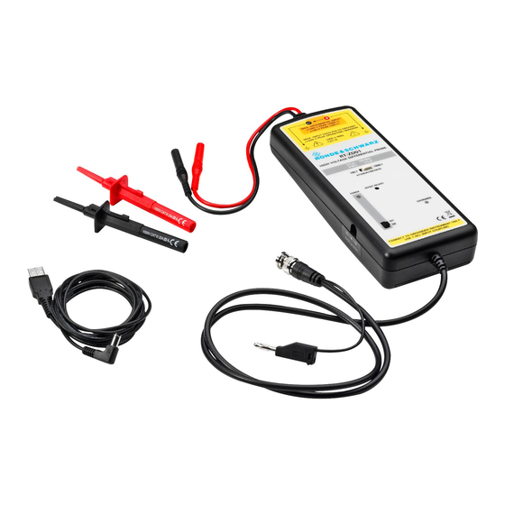
www.allice.de Allice Messtechnik GmbH ® Product Description R&S RT-ZD01 Unpacking the Instrument ● Sprung hooks (black and red) ● USB power cord ● User manual ● R&S RT‑Zxx data sheet ● Calibration certificate ● Documentation of calibration values (if ordered) Fig. -
Page 53: Description Of The Probe
www.allice.de Allice Messtechnik GmbH ® Product Description R&S RT-ZD01 Description of the Probe Accessories supplied with the instrument are listed in chapter 1.7, "Accesso- ries and Items", on page 14. Description of the Probe 1.6.1 Parts of the probe The R&S RT-ZD01 consists of the probe amplifier box, an output lead and two input leads. - Page 54 www.allice.de Allice Messtechnik GmbH ® Product Description R&S RT-ZD01 Description of the Probe 1 = Probe amplifier box 2 = Input leads 3 = Safety banana plug (4 mm) 4 = Sprung hooks 5 = Output lead 6 = BNC output connector 7 = Auxiliary ground connector Probe amplifier box Contains the high voltage divider, the active differential amplifier and other elec-...
-
Page 55: Controls And Indicators
www.allice.de Allice Messtechnik GmbH ® Product Description R&S RT-ZD01 Description of the Probe Shock hazard caused by high voltages The input leads have a jacket wear indicator. If the input lead's jacket is excessively worn, a different jacket color becomes visible. If you see this color indicator, do not use the probe. - Page 56 www.allice.de Allice Messtechnik GmbH ® Product Description R&S RT-ZD01 Description of the Probe 1 = Attenuation ratio switch 2 = Power input 3 = Power switch 4 = Offset adjustment 5 = Overrange indicator 6 = Power indicator Attenuation ratio switch Sets the attenuation of the probe to 100:1 or 1000:1.
-
Page 57: Accessories And Items
www.allice.de Allice Messtechnik GmbH ® Product Description R&S RT-ZD01 Accessories and Items Power indicator The power indicator lights up continuously if the probe is switched on and pow- ered correctly. If the probe is powered by batteries, the power indicator blinks if the voltage of the cells is too low. - Page 58 www.allice.de Allice Messtechnik GmbH ® Product Description R&S RT-ZD01 Accessories and Items Shock hazard caused by high voltages Always check the working voltage and measurement category of the acces- sory. If these values are smaller than the values of the R&S RT-ZD01 probe, make sure not to exceed the accessory limits.
-
Page 59: Putting Into Operation
www.allice.de Allice Messtechnik GmbH ® Putting into Operation R&S RT-ZD01 Connecting the Probe to R&S Oscilloscopes Putting into Operation Connecting the Probe to R&S Oscilloscopes Shock hazard caused by high voltages To avoid electric shock and personal injury, and to prevent damage to the probe or any other products connected to it, make sure that the shell of the BNC output connector is safely connected to earth ground. - Page 60 www.allice.de Allice Messtechnik GmbH ® Putting into Operation R&S RT-ZD01 Connecting the Probe to R&S Oscilloscopes Fig. 2-1: Connecting the BNC output connector and the auxiliary ground connector when using a measurement instrument without grounded inputs 3. Connect the USB power cord to the power input of the probe and to a free USB port of the oscilloscope.
- Page 61 www.allice.de Allice Messtechnik GmbH ® Putting into Operation R&S RT-ZD01 Connecting the Probe to R&S Oscilloscopes 4. Switch the power switch of the probe to ON. 5. Adjust the attenuation ratio on the probe. If you measure signals below 140 V (peak), set the attenuation to 100:1 to get higher resolution and less noise.
-
Page 62: Connecting The Probe To The Dut
www.allice.de Allice Messtechnik GmbH ® Putting into Operation R&S RT-ZD01 Connecting the Probe to the DUT c) Using a small screwdriver, turn the "Offset Adjust" screw until the wave- form meets exactly the 0 V position in the middle of the display. Fig. -
Page 63: Reducing Noise Induction
www.allice.de Allice Messtechnik GmbH ® Putting into Operation R&S RT-ZD01 Connecting the Probe to the DUT Finger guard Slider safe unsafe Fig. 2-6: Opening the sprung hook Shock hazard caused by high voltages Disconnect the sprung hooks from the DUT before disconnecting the probe from the measuring instrument. -
Page 64: Alternative Battery Operation
www.allice.de Allice Messtechnik GmbH ® Putting into Operation R&S RT-ZD01 Alternative Battery Operation Fig. 2-8: Leads, twisted Alternative Battery Operation Usually, the probe is powered by the USB power cord that is connected to a USB connector of the oscilloscope. See also: "Power input"... -
Page 65: Characteristics Of Differential Probes
www.allice.de Allice Messtechnik GmbH ® Characteristics of Differential Probes R&S RT-ZD01 Characteristics of Differential Probes A differential probe has three sockets: the positive signal socket (+), the negative signal socket (-), and the ground socket. Fig. 3-1: Input voltages on a differential probe Multiple input voltages can be defined for a differential probe: ●... -
Page 66: Common Mode Rejection Ratio (Cmrr)
www.allice.de Allice Messtechnik GmbH ® Characteristics of Differential Probes R&S RT-ZD01 Common Mode Rejection Ratio (CMRR) The output voltage V , which is displayed on the base unit, is generally obtained by superimposing the voltages generated from the differential mode input voltage and from the common mode input voltage: ... -
Page 67: Dynamic Range And Operating Voltage Window
www.allice.de Allice Messtechnik GmbH ® Characteristics of Differential Probes R&S RT-ZD01 Dynamic Range and Operating Voltage Window ● Probing on ground-referenced signals. In this case, the common mode com- ponent is always equal to half of the input voltage. Dynamic Range and Operating Voltage Window Two separate specifications are necessary in order to characterize the permissi- ble input voltage range of a differential voltage probe: ●... - Page 68 www.allice.de Allice Messtechnik GmbH ® Characteristics of Differential Probes R&S RT-ZD01 Dynamic Range and Operating Voltage Window Fig. 3-2: Dynamic range and operating voltage window for both attenuation ratios 100:1 and 1000:1 The dependencies of dynamic range, operating voltage window and attenuation ratio are shown in figure 3-2.
- Page 69 www.allice.de Allice Messtechnik GmbH ® Characteristics of Differential Probes R&S RT-ZD01 Dynamic Range and Operating Voltage Window Fig. 3-3: Signal curves a) = Two signals of ±700 V and opposing phase are applied to positive and negative inputs. At the peaks, the probe is driven with an input voltage of ±1400 V between the positive and negative signal pin.
-
Page 70: Maximum Voltage Input
www.allice.de Allice Messtechnik GmbH ® Characteristics of Differential Probes R&S RT-ZD01 Maximum Voltage Input Maximum Voltage Input The R&S RT-ZD01 high voltage differential probe is rated for CAT III environ- ments with a maximum working voltage of 1000 V (RMS) between each input lead and earth ground. -
Page 71: Maintenance And Service
www.allice.de Allice Messtechnik GmbH ® Maintenance and Service R&S RT-ZD01 Service Strategy Maintenance and Service Service Strategy Rohde & Schwarz probes are high-precision, high-performance instruments that extend the limits of today’s technological possibilities. Like all Rohde & Schwarz instruments, Rohde & Schwarz probes are of high quality and require only mini- mum service and repair. -
Page 72: Cleaning
www.allice.de Allice Messtechnik GmbH ® Maintenance and Service R&S RT-ZD01 Cleaning Cleaning To clean the exterior of the probe, use a soft cloth moistened with either distilled water or isopropyl alcohol. Before using the probe again, make sure to dry it com- pletely. - Page 73 www.allice.de Allice Messtechnik GmbH ® Functional Check R&S RT-ZD01 Functional Check The functional check is used to confirm the basic operation of the R&S RT-ZD01 high voltage differential probe using simple measurement equipment. The functional check is not suitable for verifying compliance with the probe speci- fications, since the test results are influenced by the oscilloscope used.
- Page 74 www.allice.de Allice Messtechnik GmbH ® Functional Check R&S RT-ZD01 1. Set the attenuation ratio on the probe to 100:1. 2. Connect the R&S RT-ZD01 probe to an R&S oscilloscope as described in chapter 2.1, "Connecting the Probe to R&S Oscilloscopes", on page 16.
- Page 75 www.allice.de Allice Messtechnik GmbH ® Index R&S RT-ZD01 Index Attenuation ratio ........13 Unpacking ..........8 USB power cord ........13 Batteries ..........21 Cleaning ..........29 Clipping ........... 25 CMRR ............23 Common mode input voltage ....22 Common mode range ......24 Common Mode Rejection Ratio ....
- Page 76 www.allice.de Allice Messtechnik GmbH AlliCE Messtechnik GmbH make ALLICE your partner ALLICE Messtechnik GmbH Kelsterbacher Strasse 15-19 60528 Frankfurt am Main Tel.: +49(0)69-67724-583 Fax: +49(0)69-67724-582 info@allice.de www.allice.de © 2018 Allice Messtechnik GmbH – Alle Rechte vorbehalten. © 2018 Allice Messtechnik GmbH – All rights reserved Verwendete Warenzeichen und Schutzrechte sind Eigentum der jeweiligen Hersteller.
Need help?
Do you have a question about the R&S RT-ZD01 and is the answer not in the manual?
Questions and answers