
Related Manuals for Rohde & Schwarz RT-ZHD07


Summary of Contents for Rohde & Schwarz RT-ZHD07
- Page 1 ® R&S RT-ZHD07/15/16/60 High Voltage Differential Probe User Manual (B0Iæ2) 1800258802 Version 02...
- Page 2 ® This user manual describes the following R&S RT-ZHD models and options: ● ® R&S RT-ZHD07 (1800.2307.02) ● ® R&S RT-ZHD15 (1800.2107.02) ● ® R&S RT-ZHD16 (1800.2207.02) ● ® R&S RT-ZHD60 (1800.2007.02) © 2023 Rohde & Schwarz GmbH & Co. KG Muehldorfstr.
-
Page 3: Table Of Contents
® Contents R&S RT-ZHD07/15/16/60 Contents 1 Safety and regulatory information............5 Safety instructions......................5 Labels on the product....................7 Warning messages in the documentation..............7 2 Product description................9 Key characteristics and key features................9 2.1.1 Key characteristics......................9 2.1.2 Key features........................10 Unpacking and checking.................... 11 Description of the probe.....................13... - Page 4 ® Contents R&S RT-ZHD07/15/16/60 4.4.2 Dynamic range and operating voltage window............. 28 Typical characteristics of the R&S RT‑ZHD.............. 30 4.5.1 Improve the signal integrity................... 31 4.5.2 Bandwidth........................32 4.5.3 Step response....................... 34 4.5.4 CMRR........................... 36 4.5.5 Signal loading of the input signal.................. 39 5 Maintenance and service..............40...
-
Page 5: Safety And Regulatory Information
® Safety and regulatory information R&S RT-ZHD07/15/16/60 Safety instructions 1 Safety and regulatory information The product documentation helps you to use the product safely and efficiently. Follow the instructions provided here and throughout the manual. Intended use The product is intended for the development, production and verification of electronic components and devices in industrial, administrative, and laboratory environments. - Page 6 ® Safety and regulatory information R&S RT-ZHD07/15/16/60 Safety instructions aged or broken, stop using the product. Contact Rohde & Schwarz customer service at https://www.rohde-schwarz.com/support. In these safety instructions, the term "product" covers instruments (oscilloscopes), probes and their accessories. Choosing the operating site Only use the product indoors.
-
Page 7: Labels On The Product
® Safety and regulatory information R&S RT-ZHD07/15/16/60 Warning messages in the documentation Working with hazardous voltages Voltages higher than 30 V RMS, or 42 V peak, or 60 V DC are regarded as hazardous contact voltages. Direct contact with them can cause serious injuries. - Page 8 ® Safety and regulatory information R&S RT-ZHD07/15/16/60 Warning messages in the documentation WARNING Potentially hazardous situation. Could result in death or serious injury if not avoided. CAUTION Potentially hazardous situation. Could result in minor or moderate injury if not avoided.
-
Page 9: Product Description
Sup- ported oscilloscopes are listed in the data sheet. 2.1 Key characteristics and key features 2.1.1 Key characteristics Table 2-1: Key characteristics Parameter R&S RT-ZHD07 R&S RT- R&S RT-ZHD60 ZHD15/16 Bandwidth DC - 200 MHz... -
Page 10: Key Features
® Product description R&S RT-ZHD07/15/16/60 Key characteristics and key features The probe is designed to measure electrical devices or installations of categories 0 (I), II, or III if the effective value of the measured voltage against earth ground does not exceed the maximum working voltage. -
Page 11: Unpacking And Checking
® Product description R&S RT-ZHD07/15/16/60 Unpacking and checking indicator at the input terminals" "Overrange indicator at the output terminal" on page 16. Switchable bandwidth limit The R&S RT‑ZHD contains a switchable analog lowpass with a cutoff frequency of 5 MHz. For measurements with long leads, it is convenient to reduce overshot and noise by activating the bandwidth limit. - Page 12 ® Product description R&S RT-ZHD07/15/16/60 Unpacking and checking Delivery notes ‑ ZHD probe with accessories Figure 2-1: R&S RT The following items are included in the delivery: ● R&S RT‑ZHD high-voltage differential probe ● Carrying case ● Pince clip (black and red) ●...
-
Page 13: Description Of The Probe
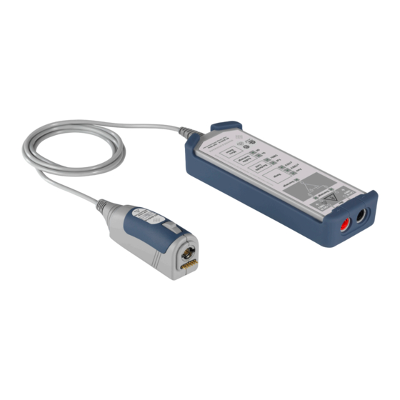
® Product description R&S RT-ZHD07/15/16/60 Description of the probe 2.3 Description of the probe The R&S RT‑ZHD consists of the probe control box, two input leads, a probe cable and a probe box. ‑ ZHD probe Figure 2-2: R&S RT... -
Page 14: Probe Control Box
® Product description R&S RT-ZHD07/15/16/60 Description of the probe (1) Rohde & Schwarz probe interface with 7 mm (276 mil) coaxial connector and 6 pogo pins (2) Release knob 2.3.2 Probe control box Contains the high-voltage divider, the active differential amplifier and other electronic components. - Page 15 ® Product description R&S RT-ZHD07/15/16/60 Description of the probe Figure 2-3: Probe control box 1 = Overrange indicators at each of the inputs 2 = Overrange indicator at the output 3 = Range: attenuation setting 4 = Bandwidth limit 5 MHz...
- Page 16 ® Product description R&S RT-ZHD07/15/16/60 Description of the probe ● "Attenuation low" You can select the attenuation of the probe and it is not changed by the vertical scope settings. This setting is characterized by less noise. If the attenuation is changed from "high"...
-
Page 17: Probe Cable
® Product description R&S RT-ZHD07/15/16/60 Accessories and items 2.3.3 Probe cable Connects the probe control box to the probe box. Its length of around 150 cm allows for a comfortable working distance to the base unit. 2.3.4 Input leads The delivered input leads provide flexible contact to the DUT even in confined physical conditions. - Page 18 ® Product description R&S RT-ZHD07/15/16/60 Accessories and items Table 2-3: Supplied accessories Item Quantity Description Test clip Maximum rating: 1000 V (RMS) CAT IV Pincer clip Maximum rating: 1000 V (RMS) CAT III Safety Alligator clip Maximum rating: 1000 V (RMS) CAT III...
-
Page 19: Service Accessories
® Product description R&S RT-ZHD07/15/16/60 Accessories and items Item Quantity Description Short Leads (17cm) Maximum rating: 1000 V (RMS) CAT III Test leads Maximum rating: 1000 V (RMS) CAT III Two hinged ferrite cores With key for easier opening Soft case with foam inlay For a list of spare parts, see Chapter 5.7, "Spare... -
Page 20: Dimensions
® Product description R&S RT-ZHD07/15/16/60 Dimensions Table 2-4: Service accessories Item Description R&S RT-ZK2 The service kit is used to calibrate the probe, to do perfor- mance tests, and for servicing. The service kit includes all adapters and accessories to connect the probe to the required measuring instruments. -
Page 21: Connecting The Probe
® Connecting the probe R&S RT-ZHD07/15/16/60 Connecting the probe to the oscilloscope 3 Connecting the probe 3.1 Handling the probe The R&S RT‑ZHD can withstand a moderate amount of physical and electrical stress. To avoid damage, treat the probe with care: ●... -
Page 22: Identification Of The Probe
® Connecting the probe R&S RT-ZHD07/15/16/60 Connecting the probe to the DUT Figure 3-1: Connecting the probe to the Rohde & Schwarz oscilloscope 3. Do a functional check as described in Chapter 6, "Functional check", on page 43. ► To disconnect the probe: a) Press and hold the release button (3). - Page 23 ® Connecting the probe R&S RT-ZHD07/15/16/60 Connecting the probe to the DUT lower than the specified voltage. Read and observe Chapter 1.1, "Safety instructions", on page 5. To connect the probe to the DUT 1. Switch off the test circuit.
-
Page 24: Reducing Noise Induction
® Connecting the probe R&S RT-ZHD07/15/16/60 Reducing noise induction 2. Disconnect the clips from the DUT. Observe the safety measures described in step 5 of the connecting procedure. 3. Remove the input leads from the probe control box. 4. Disconnect the probe from the oscilloscope. Disconnection from the measuring instrument is always the last step to ensure proper grounding during the complete measurement process. -
Page 25: Features And Characteristics Of R&S Rt-Zhd Probes
® Features and characteristics of R&S RT‑ZHD probes R&S RT-ZHD07/15/16/60 R&S ProbeMeter 4 Features and characteristics of R&S RT‑ZHD probes 4.1 Micro button The micro button provides easy and quick access to important functions of the Rohde & Schwarz oscilloscope. After a function has been assigned, pressing the micro button remotely controls this specific function on the base unit. -
Page 26: Offset Compensation
® Features and characteristics of R&S RT‑ZHD probes R&S RT-ZHD07/15/16/60 Offset compensation ● Measurement range is ±maximum allowable voltage + offset compensation setting. Maximum measurement accuracy is achieved when offset compensation is switched off. 4.3 Offset compensation The offset compensation can compensate a DC component of the input signal between the positive and negative input in front of the active amplifier in the probe control box. -
Page 27: Characteristics Of Differential Probes
® Features and characteristics of R&S RT‑ZHD probes R&S RT-ZHD07/15/16/60 Characteristics of differential probes 4.4 Characteristics of differential probes A differential probe has three sockets: the positive signal socket (+), the negative sig- nal socket (-), and the signal output which is connected to ground. -
Page 28: Common Mode Rejection Ratio (Cmrr)
® Features and characteristics of R&S RT‑ZHD probes R&S RT-ZHD07/15/16/60 Characteristics of differential probes In this equation, A is the amplification of the differential mode input voltage and A is the amplification of the common mode input voltage. An ideal differential probe is expressed as A = 1 and A = 0. - Page 29 ® Features and characteristics of R&S RT‑ZHD probes R&S RT-ZHD07/15/16/60 Characteristics of differential probes Figure 4-3: Dynamic range and operating voltage window for both attenuation ratios 50:1 and 500:1 (e.g. R&S RT-ZHD15) The dependencies of dynamic range, operating voltage window and attenuation ratio...
-
Page 30: Typical Characteristics Of The R&S Rt-Zhd
® Features and characteristics of R&S RT‑ZHD probes R&S RT-ZHD07/15/16/60 Typical characteristics of the R&S RT‑ZHD Figure 4-4: Signal curves (e.g. R&S RT-ZHD15) a) = Two signals of ±750 V and opposing phase are applied to positive and negative inputs. At the peaks, the probe is driven with an input voltage of ±1500 V between the positive and negative signal pin. -
Page 31: Improve The Signal Integrity
® Features and characteristics of R&S RT‑ZHD probes R&S RT-ZHD07/15/16/60 Typical characteristics of the R&S RT‑ZHD ● High signal integrity of the transferred signal: With an ideal probe, the output signal that is transferred to the base unit would be identical to the input signal between the probe tips, and signal integrity would be extremely high. -
Page 32: Bandwidth
® Features and characteristics of R&S RT‑ZHD probes R&S RT-ZHD07/15/16/60 Typical characteristics of the R&S RT‑ZHD Figure 4-6: Improvement with additional hinged ferrite cores Figure 4-6, you can see the improvement in the signal integrity. The curve "Step with ferrite" is artificially delayed for 8 ns for a better view. The ferrite cores do not add any additional delay. - Page 33 ® Features and characteristics of R&S RT‑ZHD probes R&S RT-ZHD07/15/16/60 Typical characteristics of the R&S RT‑ZHD ‑ ZHD (Attenuation 'High') Figure 4-7: Amplitude frequency response of the R&S RT ‑ ZHD (Attenuation 'Low') Figure 4-8: Amplitude frequency response of the R&S RT The bandwidth: ●...
-
Page 34: Step Response
® Features and characteristics of R&S RT‑ZHD probes R&S RT-ZHD07/15/16/60 Typical characteristics of the R&S RT‑ZHD ● Specifies the transferable spectrum for other waveforms. E.g., with square wave signals, the fifth harmonic should still be within the bandwidth for a high signal integrity. - Page 35 ® Features and characteristics of R&S RT‑ZHD probes R&S RT-ZHD07/15/16/60 Typical characteristics of the R&S RT‑ZHD ‑ ZHD (Attenuation 'Low') Figure 4-10: Step response of the R&S RT The behavior of all R&S RT‑ZHD is similar for more than 30 ns after a step. The curves...
-
Page 36: Cmrr
® Features and characteristics of R&S RT‑ZHD probes R&S RT-ZHD07/15/16/60 Typical characteristics of the R&S RT‑ZHD ‑ ZHD16 (Attenuation 'Low') Figure 4-12: Typical step response e.g. of the R&S RT 4.5.4 CMRR The CMRR is good for low-frequency signals, but it continuously decreases for higher frequencies. - Page 37 ® Features and characteristics of R&S RT‑ZHD probes R&S RT-ZHD07/15/16/60 Typical characteristics of the R&S RT‑ZHD ‑ ZHD probes with serial numbers >200000 as a function of fre- Figure 4-13: Typical CMRR of R&S RT quency with attenuation 'Low' ‑ ZHD probes with serial numbers >200000 as a function of fre- Figure 4-14: Typical CMRR of R&S RT...
- Page 38 ® Features and characteristics of R&S RT‑ZHD probes R&S RT-ZHD07/15/16/60 Typical characteristics of the R&S RT‑ZHD ‑ ZHD probes with serial numbers <200000 as a function of fre- Figure 4-15: Typical CMRR of R&S RT quency with attenuation 'Low' ‑ ZHD probes with serial numbers <200000 as a function of fre- Figure 4-16: Typical CMRR of R&S RT...
-
Page 39: Signal Loading Of The Input Signal
® Features and characteristics of R&S RT‑ZHD probes R&S RT-ZHD07/15/16/60 Typical characteristics of the R&S RT‑ZHD 4.5.5 Signal loading of the input signal The previous section explained the transfer function and step response of the probe. This section describes how the probe influences the input signal. The input signal load- ing caused by the probe is determined by its input impedance. -
Page 40: Maintenance And Service
® Maintenance and service R&S RT-ZHD07/15/16/60 Contacting customer support 5 Maintenance and service Like all Rohde & Schwarz products, Rohde & Schwarz probes and adapters are of high quality and require only minimum service and repair. However, if service or calibration is needed, contact your Rohde &... -
Page 41: Returning For Servicing
® Maintenance and service R&S RT-ZHD07/15/16/60 Disposal 5.3 Returning for servicing Use the original packaging to return your R&S RT‑ZHD to your Rohde & Schwarzser- vice center. A list of all service centers is available on: www.services.rohde-schwarz.com If you cannot use the original packaging, consider the following: 1. -
Page 42: Spare Parts
Use the order numbers provided in the following table. ‑ ZHD Table 5-1: Probe and accessory spare parts for R&S RT Pos. Item Description Part number R&S RT-ZHD07 1800.2307.02 R&S RT-ZHD15 1800.2107.02 R&S RT-ZHD16 1800.2207.02 R&S RT-ZHD60 1800.2007.02 Protector 1800.2488.00... -
Page 43: Functional Check
® Functional check R&S RT-ZHD07/15/16/60 6 Functional check The functional check confirms the basic operation of the R&S RT‑ZHD high-voltage dif- ferential probe. The functional check is not suitable for verifying compliance with the probe specifications. 1. Connect the R&S RT‑ZHD probe to an R&S oscilloscope as described in Chap- ter 3.2, "Connecting the probe to the...
Need help?
Do you have a question about the RT-ZHD07 and is the answer not in the manual?
Questions and answers